EP1533866A1 - Adaptive Phasengesteuerte Gruppenantenne mit digitaler Keulenformung - Google Patents
Adaptive Phasengesteuerte Gruppenantenne mit digitaler Keulenformung Download PDFInfo
- Publication number
- EP1533866A1 EP1533866A1 EP04104960A EP04104960A EP1533866A1 EP 1533866 A1 EP1533866 A1 EP 1533866A1 EP 04104960 A EP04104960 A EP 04104960A EP 04104960 A EP04104960 A EP 04104960A EP 1533866 A1 EP1533866 A1 EP 1533866A1
- Authority
- EP
- European Patent Office
- Prior art keywords
- antenna
- signal
- cluster
- sub
- clusters
- Prior art date
- Legal status (The legal status is an assumption and is not a legal conclusion. Google has not performed a legal analysis and makes no representation as to the accuracy of the status listed.)
- Granted
Links
Images


Classifications
-
- G—PHYSICS
- G01—MEASURING; TESTING
- G01S—RADIO DIRECTION-FINDING; RADIO NAVIGATION; DETERMINING DISTANCE OR VELOCITY BY USE OF RADIO WAVES; LOCATING OR PRESENCE-DETECTING BY USE OF THE REFLECTION OR RERADIATION OF RADIO WAVES; ANALOGOUS ARRANGEMENTS USING OTHER WAVES
- G01S13/00—Systems using the reflection or reradiation of radio waves, e.g. radar systems; Analogous systems using reflection or reradiation of waves whose nature or wavelength is irrelevant or unspecified
- G01S13/02—Systems using reflection of radio waves, e.g. primary radar systems; Analogous systems
- G01S13/06—Systems determining position data of a target
- G01S13/42—Simultaneous measurement of distance and other co-ordinates
- G01S13/426—Scanning radar, e.g. 3D radar
-
- G—PHYSICS
- G01—MEASURING; TESTING
- G01S—RADIO DIRECTION-FINDING; RADIO NAVIGATION; DETERMINING DISTANCE OR VELOCITY BY USE OF RADIO WAVES; LOCATING OR PRESENCE-DETECTING BY USE OF THE REFLECTION OR RERADIATION OF RADIO WAVES; ANALOGOUS ARRANGEMENTS USING OTHER WAVES
- G01S13/00—Systems using the reflection or reradiation of radio waves, e.g. radar systems; Analogous systems using reflection or reradiation of waves whose nature or wavelength is irrelevant or unspecified
- G01S13/02—Systems using reflection of radio waves, e.g. primary radar systems; Analogous systems
- G01S13/06—Systems determining position data of a target
- G01S13/46—Indirect determination of position data
- G01S13/48—Indirect determination of position data using multiple beams at emission or reception
-
- H—ELECTRICITY
- H01—ELECTRIC ELEMENTS
- H01Q—ANTENNAS, i.e. RADIO AERIALS
- H01Q25/00—Antennas or antenna systems providing at least two radiating patterns
-
- G—PHYSICS
- G01—MEASURING; TESTING
- G01S—RADIO DIRECTION-FINDING; RADIO NAVIGATION; DETERMINING DISTANCE OR VELOCITY BY USE OF RADIO WAVES; LOCATING OR PRESENCE-DETECTING BY USE OF THE REFLECTION OR RERADIATION OF RADIO WAVES; ANALOGOUS ARRANGEMENTS USING OTHER WAVES
- G01S13/00—Systems using the reflection or reradiation of radio waves, e.g. radar systems; Analogous systems using reflection or reradiation of waves whose nature or wavelength is irrelevant or unspecified
- G01S13/02—Systems using reflection of radio waves, e.g. primary radar systems; Analogous systems
- G01S13/06—Systems determining position data of a target
- G01S13/08—Systems for measuring distance only
- G01S13/10—Systems for measuring distance only using transmission of interrupted, pulse modulated waves
- G01S13/24—Systems for measuring distance only using transmission of interrupted, pulse modulated waves using frequency agility of carrier wave
Definitions
- the present invention relates to the realization of an antenna adaptive multibeam beamforming by calculation, cut off in subnets.
- This antenna makes it possible in particular to form bundles devoid of lobes of parasitic networks.
- This device applies particularly in the fight against the jamming of radars.
- These adaptive FFC antennas consist of a large number of transmit / receive modules still called T / R modules.
- the T / R modules are combined together to form subnets.
- Each subnet behaves like a basic antenna having its own plan and phase center.
- the formation of a beam is done by combining the signals from the subnetworks which constitute the global antenna.
- To constitute the signal corresponding to a beam given each signal coming from a subnet is assigned a gain and of a determined phase shift. Then all the signals thus corrected are are.
- the values of the gain and phase weightings of each subnetwork are determined by known methods, coming from the field of adaptive anti-jamming, the subnetwork structure being developed at anti-jamming purposes.
- the overall orientation of the beam bundle of a multibeam antenna is realized while playing on the phase relative signals from the T / R modules. By doing so, we modify the overall orientation of the phase plan of the antenna.
- Phase plans of the subnetworks are in most cases not oriented in the direction of the beam to form.
- the only accessible way to form a beam in a given direction is to adjust the phase of the signal from each sub-network to obtain, by recombination, the desired beam.
- the subnets therefore constitute elementary antennas that present by construction distant phase centers one of the other.
- the distance between their phase centers is large compared to the wave length.
- the phasing of signals from different sub-networks leads, during the formation of the beam, the appearance parasitic lobes.
- These parasitic lobes or lobes of networks are the reproduction of the desired beam lobe, according to determined directions by the distance separating the phase centers from the subnetworks.
- the current FFC antennas form beams that have an unwanted spatial periodicity.
- An object of the invention is in particular to overcome the disadvantages cited.
- the invention relates to an adaptive FFC antenna allowing the simultaneous constitution of several beams.
- the antenna according to the invention has particular characteristic to present for each sub-network phase planes oriented perpendicular to the direction of each of the beams.
- the antenna according to the invention comprises in particular T / R modules clustered. Clusters are themselves assembled in groups to form subnets and the combination of subnets forms the beams.
- the overall direction of the plan phase of a multibeam antenna is performed, as for a conventional single-beam electronic scanning antenna, playing on the relative phase of the signals from the T / R modules.
- the antenna is considered to retain constant orientation and that a zero phase shift is applied to the T / R modules.
- Figure 1 illustrates in graphic form the disadvantages induced by the embodiment of current adaptive FFC antennas.
- This figure represents in a single plane and for a given beam, oriented in an axis taken as a reference, the emission and reception diagrams.
- the emission diagram 11 being necessarily broad, the energy susceptible to be received by beam 12 is not significantly different from that likely to be received by the lobes of networks 13.
- the appearance of a jamming signal in one of these lobes of networks will affect very importantly the detection of possible echoes by the beam corresponding.
- lattice lobes have an angular repetitivity ⁇ which depends on the ratio , ratio of the distance of the phase centers of the sub-networks to the wavelength of the signal.
- Figure 2 presents in a pictorial way the structural origin of the appearance of the network lobes phenomenon previously described in the case of a single beam.
- subnets are represented in this figure as being contiguous and of the same size.
- the phase plans of the subnetworks are oriented in a fixed direction, identical for all beams formed. Different structures, for example with size networks different and with some overlap, are obviously possible.
- the line 21 shows the phase plan of the global antenna and the angle of misalignment of the beam to be formed, the direction of which is materialized by the 22.
- the straight line 23 represents the ideal phase plane to be get the desired misalignment. This ideal plan can only be achieved by adjusting the phase shift at the T / R modules, which can not be, as this has been said previously, carried out simultaneously for each of beams to form.
- each step of curve 24 represents the phase plan of the sub-network corresponding.
- the combination of signals is represented in the figure by the dotted arrows 27.
- the formation of the desired beam 22 is accompanied also that of the network lobes 25 whose appearance is linked to the discontinuities of curve 24.
- the reception pattern G n associated with a beam F n has an expression of the following form:
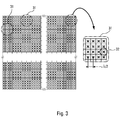
- FIG. 3 illustrates the principle of organizing an FFC antenna adaptive device according to the invention.
- the T / R modules are only more grouped directly into subnets but are first combined by small groups to form basic units 31 called clusters.
- a cluster consists of a group of T / R modules connected together to others through microwave combiner circuits. As on the FIG. 3, the clusters constituting the antenna are for example disjoint and their juxtaposition reconstitutes the entire antenna.
- the cluster represents the basic element of an adaptive FFC antenna according to the invention.
- the number Q of T / R modules used in composing a cluster is any and can, for example, vary from one cluster to another in a same antenna.
- FIG. consisting of an assembly of identical clusters each formed of sixteen T / R modules 32.
- the T / R modules are spaced apart from one another distance close to the half-wavelength of the signal.
- Each T / R module is also equipped with an amplitude and phase control, which allows guide the overall phase plan of the antenna.
- FIG. 4 illustrates the internal structure of a cluster 31 according to the invention.
- the output of each T / R module 32 is distributed in parallel on the inputs of several independent microwave combiners.
- a combiner C 0 , 41 realizes the sum of the signals 42 from the different T / R modules. It thus produces a signal S 0 , 43, corresponding to the reception channel relative to the antenna beam F 0 , perpendicular to the phase plane of the antenna.
- the other combiners 44 perform the synthesis of corrective signals c fn , 45, corresponding to a weighted sum of the signals from the different T / R modules. This weighting is performed in amplitude and phase.
- each antenna beam formed It is specific to each antenna beam formed and makes it possible to obtain for each T / R module the signal corresponding to the difference existing between the signal actually received by the T / R module and the theoretical signal that would be received if the The phase of the T / R module was oriented perpendicular to the direction of the beam. For a given real phase plane, this difference will be zero only for the signal received from a direction perpendicular to the phase plane of the module T / R, this direction corresponding for example to the antenna beam F 0 .
- a cluster therefore comprises a summing circuit making it possible to constitute the beam F 0 , for which the difference between the real signal and the theoretical signal is zero. It also includes as many combiner circuits as there are other antenna beams to form. It thus has an output 43 corresponding to the signal relating to the beam F 0 . and as many corrective outputs 45 as beams to form.
- FIG. 5 illustrates, in a pictorial manner, the imperfections related to subnetting, and the manner in which it is possible to correct these imperfections thanks to the cluster structure of the antenna according to the invention.
- This illustration represents a partial enlarged view of the illustration of an antenna composed of sub-networks as shown in FIG. 2.
- the bearings 51 represent the phase planes of the different sub-networks that make up the antenna.
- the line segments 52 include the orientation of the same phase planes for forming a beam without grating lobes in a given direction. This direction is symbolized by the arrows 52. Since the orientation of the overall phase plane of the antenna is represented by the line 23, it can be seen that the positioning of the phase planes of the different sub-networks represents only an approximation.
- This positioning is achieved by applying to each signal from a T / R modulates a same phase shift ⁇ re represented by the vectors 53. The signals thus phase shifted are then summed to form the receiving path of the considered subnet. The resulting approximation is responsible for the appearance of lattice lobes.
- the antenna according to the invention makes it possible to correct the imperfections of the signal obtained.
- the cluster provides a correction signal developed by performing a weighted sum of the signals from the T / R modules that compose it.
- an elementary corrective signal is thus obtained that makes it possible to compensate for the difference ⁇ existing between the phase shift actually applied to the modulating T / R and the theoretical phase shift enabling a beam devoid of lobes to be obtained. networks.
- the correction signals are illustrated in FIG. 5 in the form of the vectors 56.
- the elementary corrective signals corresponding to the same beam F i are summed so as to constitute a corrective signal sum c Fn .
- information is available to form beams without network lobes.
- FIG. 6 schematically shows an example of complete structure of the antenna according to the invention.
- the outputs 34 of the T / R modules are distributed over different clusters 31.
- the outputs 43 of several clusters forming the same sub-network are applied to the inputs of a summing circuit 61 so as to produce, from the signals s 0.i from each cluster of the sub-network, a signal 62 corresponding to the signal S 0.r received by the sub-network r in the direction of the beam F 0 perpendicular to the phase plane of the antenna.
- the outputs 45 of all clusters corresponding to the same beam are applied to the inputs of a summing circuit 63 so as to obtain, from the signals c nk from each cluster, a corrector signal C n , 64
- This signal makes it possible to reconstitute the signal received by the antenna in the direction of the beam F n .
- the structure therefore has as many summing circuits as there are sub-networks and beams to form.
- the outputs of the different summing circuits are then applied to receivers 65, integrated or not to the antenna, which perform the demodulation and digitization of the signals.
- the number of receivers required here is advantageously equal to the sum of the number of sub-networks constituting the antenna and the number of beams formed minus one.
- the beamforming by the calculation is here performed almost conventionally by calculating the matrix W correction coefficients to be applied to the signal from each sub-network.
- ⁇ 0 corresponds to the direction vector which defines the overall phase shift to be applied to the signals coming from the different sub-networks.
- ⁇ 0 characterizing a conventional sub-network antenna, in that it has as many lines as sub-networks and an additional line relating to the correction. corresponding to the beam considered.
- R x represents the covariance matrix of the signal composed of the signals coming from the different sub-networks and the correction signal relating to the beam considered.
- R x -1 has one more line than in the case of a conventional sub-array antenna. In the absence of jammers the matrix R x -1 corresponds to a unit matrix. It therefore appears possible to produce, from the antenna according to the invention, a multibeam antenna whose beams are advantageously devoid of lattice lobes. Such an antenna has the advantage of requiring only a reduced number of additional receivers compared to a conventional multibeam antenna having the same number of sub-networks.
- the number of additional receivers is for example equal to N-1.
- the formation of the beam F 0 is performed by summing the signals S 0.r from the different sub-networks. The sum of the different signals S 0.r constitutes the global signal S 0 .
- the formation of the other beams F n is carried out by performing the correction of the signal S 0 corresponding to the beam F 0 by the corrector signal C n relating to the beam F n .
Landscapes
- Engineering & Computer Science (AREA)
- Radar, Positioning & Navigation (AREA)
- Remote Sensing (AREA)
- Computer Networks & Wireless Communication (AREA)
- Physics & Mathematics (AREA)
- General Physics & Mathematics (AREA)
- Variable-Direction Aerials And Aerial Arrays (AREA)
Applications Claiming Priority (2)
| Application Number | Priority Date | Filing Date | Title |
|---|---|---|---|
| FR0313493A FR2862440B1 (fr) | 2003-11-18 | 2003-11-18 | Architecture d'antenne adaptative multifaisceaux a formation de faisceaux par le calcul |
| FR0313493 | 2003-11-18 |
Publications (2)
| Publication Number | Publication Date |
|---|---|
| EP1533866A1 true EP1533866A1 (de) | 2005-05-25 |
| EP1533866B1 EP1533866B1 (de) | 2008-10-01 |
Family
ID=34430013
Family Applications (1)
| Application Number | Title | Priority Date | Filing Date |
|---|---|---|---|
| EP20040104960 Expired - Lifetime EP1533866B1 (de) | 2003-11-18 | 2004-10-11 | Adaptive Phasengesteuerte Gruppenantenne mit digitaler Keulenformung |
Country Status (3)
| Country | Link |
|---|---|
| EP (1) | EP1533866B1 (de) |
| DE (1) | DE602004016808D1 (de) |
| FR (1) | FR2862440B1 (de) |
Cited By (6)
| Publication number | Priority date | Publication date | Assignee | Title |
|---|---|---|---|---|
| WO2007023371A1 (en) * | 2005-08-24 | 2007-03-01 | Reutech Radar Systems (Proprietary) Limited | Grating lobe assisted search radar system utilising antenna with multiple elements |
| CN102142609A (zh) * | 2010-12-16 | 2011-08-03 | 哈尔滨工业大学 | 具有低旁瓣特性的子阵级自适应数字波束形成器 |
| WO2012056357A1 (en) * | 2010-10-28 | 2012-05-03 | Koninklijke Philips Electronics N.V. | System and method for presence detection |
| EP3315994A1 (de) * | 2016-10-27 | 2018-05-02 | Thales | Mehrstrahliger fmcw-radar, insbesondere für kraftfahrzeug |
| US10520597B2 (en) * | 2016-12-09 | 2019-12-31 | Honeywell International Inc. | Aircraft radar system for bird and bat strike avoidance |
| US11079489B2 (en) | 2017-02-28 | 2021-08-03 | Honeywell International Inc. | Weather radar detection of objects |
Families Citing this family (2)
| Publication number | Priority date | Publication date | Assignee | Title |
|---|---|---|---|---|
| FR2864710B1 (fr) | 2003-12-24 | 2006-03-24 | Thales Sa | Procede d'optimisation de la definition d'une structure d' antenne ffc multifaisceaux a sous-reseaux imbriques |
| CN109324322B (zh) * | 2018-10-31 | 2020-11-20 | 中国运载火箭技术研究院 | 一种基于被动相控阵天线的测向与目标识别方法 |
Citations (1)
| Publication number | Priority date | Publication date | Assignee | Title |
|---|---|---|---|---|
| FR2838244A1 (fr) * | 2002-04-05 | 2003-10-10 | Thales Sa | Antenne adaptative multifaisceaux a formation de faisceaux par le calcul et radar comportant une telle antenne |
-
2003
- 2003-11-18 FR FR0313493A patent/FR2862440B1/fr not_active Expired - Fee Related
-
2004
- 2004-10-11 DE DE200460016808 patent/DE602004016808D1/de not_active Expired - Lifetime
- 2004-10-11 EP EP20040104960 patent/EP1533866B1/de not_active Expired - Lifetime
Patent Citations (1)
| Publication number | Priority date | Publication date | Assignee | Title |
|---|---|---|---|---|
| FR2838244A1 (fr) * | 2002-04-05 | 2003-10-10 | Thales Sa | Antenne adaptative multifaisceaux a formation de faisceaux par le calcul et radar comportant une telle antenne |
Non-Patent Citations (3)
| Title |
|---|
| HANSEN R C: "Suppression of sub-array quantization lobes", PHASED ARRAY SYSTEMS AND TECHNOLOGY, 2000. PROCEEDINGS. 2000 IEEE INTERNATIONAL CONFERENCE ON DANA POINT, CA, USA 21-25 MAY 2000, PISCATAWAY, NJ, USA,IEEE, US, 21 May 2000 (2000-05-21), pages 311 - 314, XP010504598, ISBN: 0-7803-6345-0 * |
| LAM L K ET AL: "S-band electronically scanned active phased array antenna", 2000 IEEE AEROSPACE CONFERENCE, vol. 5, 18 March 2000 (2000-03-18) - 25 March 2000 (2000-03-25), Piscataway, NJ, USA, pages 67 - 72, XP010517151 * |
| SMOLKO J A: "Optimization of pattern sidelobes in arrays with regular subarray architectures", ANTENNAS AND PROPAGATION SOCIETY INTERNATIONAL SYMPOSIUM, 1998. IEEE ATLANTA, GA, USA 21-26 JUNE 1998, NEW YORK, NY, USA,IEEE, US, 21 June 1998 (1998-06-21), pages 756 - 759, XP010292312, ISBN: 0-7803-4478-2 * |
Cited By (8)
| Publication number | Priority date | Publication date | Assignee | Title |
|---|---|---|---|---|
| WO2007023371A1 (en) * | 2005-08-24 | 2007-03-01 | Reutech Radar Systems (Proprietary) Limited | Grating lobe assisted search radar system utilising antenna with multiple elements |
| WO2012056357A1 (en) * | 2010-10-28 | 2012-05-03 | Koninklijke Philips Electronics N.V. | System and method for presence detection |
| CN102142609A (zh) * | 2010-12-16 | 2011-08-03 | 哈尔滨工业大学 | 具有低旁瓣特性的子阵级自适应数字波束形成器 |
| EP3315994A1 (de) * | 2016-10-27 | 2018-05-02 | Thales | Mehrstrahliger fmcw-radar, insbesondere für kraftfahrzeug |
| FR3058227A1 (fr) * | 2016-10-27 | 2018-05-04 | Thales Sa | Radar fmcw multifaisceaux, notamment pour automobile |
| US10620305B2 (en) | 2016-10-27 | 2020-04-14 | Thales | Multibeam FMCW radar, in particular for automobile |
| US10520597B2 (en) * | 2016-12-09 | 2019-12-31 | Honeywell International Inc. | Aircraft radar system for bird and bat strike avoidance |
| US11079489B2 (en) | 2017-02-28 | 2021-08-03 | Honeywell International Inc. | Weather radar detection of objects |
Also Published As
| Publication number | Publication date |
|---|---|
| FR2862440A1 (fr) | 2005-05-20 |
| FR2862440B1 (fr) | 2005-12-30 |
| EP1533866B1 (de) | 2008-10-01 |
| DE602004016808D1 (de) | 2008-11-13 |
Similar Documents
| Publication | Publication Date | Title |
|---|---|---|
| EP0014650B1 (de) | Adaptives Höchstfrequenz-Raumfilter und dessen Verfahren der Anwendung zur Abschwächung oder Unterdrückung der Nebenzipfel des Strahlungsdiagrammes einer Antenne | |
| EP0497652A1 (de) | Vorrichtung zur elektronischen Steuerung des Strahlungsdiagrammes einer Einfach-/Mehrfach-Strahlenantenne mit variabler Richtung und/oder Breite | |
| EP3503431B1 (de) | Verfahren zur mehrfachstrahlabdeckung durch gruppieren von elementarstrahlen derselben farbe, und nutzlast von telekommunikationsvorgängen zur umsetzung dieses verfahrens | |
| EP2194602A1 (de) | Antenne mit gemeinsam benützte Elementarstrahler und Verfahren zum Entwurf einer Mehrstrahlantenne mit gemeinsam benützte Elementarstrahler | |
| FR2965362A1 (fr) | Radar a grande couverture angulaire, notamment pour la fonction d'evitement d'obstacle a bord d'aeronefs autopilotes | |
| CA2821250C (fr) | Antenne d'emission et de reception multifaisceaux a plusieurs sources par faisceau, systeme d'antennes et systeme de telecommunication par satellite comportant une telle antenne | |
| FR3076137B1 (fr) | Procede de couverture multifaisceaux par regroupement de faisceaux elementaires de couleurs differentes, et charge utile de telecommunications pour mettre en oeuvre un tel procede | |
| WO2018141852A1 (fr) | Antenne elementaire a dispositif rayonnant planaire | |
| FR2663469A1 (fr) | Dispositif d'alimentation a des elements rayonnants d'une antenne reseau, et son application a une antenne d'un systeme d'aide a l'atterrissage du type mls. | |
| EP3176875A1 (de) | Aufbau einer aktiven hybriden rekonfigurierbaren strahlbildungsantenne | |
| EP1533866B1 (de) | Adaptive Phasengesteuerte Gruppenantenne mit digitaler Keulenformung | |
| EP0451497A1 (de) | Verfahren zur Formung des Strahlendiagrammes einer aktiven Radarantenne mit elektronisch gesteuerter Ablenkung, und Antenne dazu | |
| FR2541518A1 (fr) | Dispositif d'alimentation d'une antenne reseau a faisceau de balayage | |
| EP0288988B1 (de) | Adaptives Antennensystem für Hochfrequenz, insbesondere für den UHF-Bereich | |
| EP1351333A2 (de) | Adaptive Gruppenantenne und Radar mit einer solchen Antenne | |
| EP3159965B1 (de) | Antennennetzsender für ein monoimpulsradarsystem | |
| EP3945636B1 (de) | Verfahren zur veränderung des strahlungsdiagramms eines antennennetzes und radar zur umsetzung eines solchen verfahrens | |
| EP0638956A1 (de) | Aktive Antenne mit elektronischem Absuchen in Azimut und Elevation, insbesondere für Mikrowellen-Abbildung mittels Satellit | |
| EP1233282B1 (de) | Vorrichtung mit verteilten Sende- und Empfangsantennen, insbesondere für Radar mit synthetischer Emission und Strahlbildung | |
| EP1107359A1 (de) | Strahlungsquelle für eine Sende-/Empfangsantenne an Bord eines Satelliten | |
| EP1000445B1 (de) | Gruppenantenne für basisstation zur funkverbindung mit mobilen teilnehmern | |
| EP3155689B1 (de) | Flachantenne zur satellitenkommunikation | |
| FR2828583A1 (fr) | Procede de fermeture d'une antenne a balayage electronique, procede de reglage et dephaseur d'une telle antenne | |
| FR2773269A1 (fr) | Dispositif large bande de detection, notamment de radars | |
| EP1385019A1 (de) | Entstörungsvorrichtung, insbesondere für Radargeräte mit aktiven Gruppenantennen |
Legal Events
| Date | Code | Title | Description |
|---|---|---|---|
| PUAI | Public reference made under article 153(3) epc to a published international application that has entered the european phase |
Free format text: ORIGINAL CODE: 0009012 |
|
| AK | Designated contracting states |
Kind code of ref document: A1 Designated state(s): AT BE BG CH CY CZ DE DK EE ES FI FR GB GR HU IE IT LI LU MC NL PL PT RO SE SI SK TR |
|
| AX | Request for extension of the european patent |
Extension state: AL HR LT LV MK |
|
| AKX | Designation fees paid | ||
| 17P | Request for examination filed |
Effective date: 20050811 |
|
| RBV | Designated contracting states (corrected) |
Designated state(s): DE GB IT NL |
|
| REG | Reference to a national code |
Ref country code: DE Ref legal event code: 8566 |
|
| GRAP | Despatch of communication of intention to grant a patent |
Free format text: ORIGINAL CODE: EPIDOSNIGR1 |
|
| GRAS | Grant fee paid |
Free format text: ORIGINAL CODE: EPIDOSNIGR3 |
|
| GRAA | (expected) grant |
Free format text: ORIGINAL CODE: 0009210 |
|
| AK | Designated contracting states |
Kind code of ref document: B1 Designated state(s): DE GB IT NL |
|
| REG | Reference to a national code |
Ref country code: GB Ref legal event code: FG4D Free format text: NOT ENGLISH |
|
| REF | Corresponds to: |
Ref document number: 602004016808 Country of ref document: DE Date of ref document: 20081113 Kind code of ref document: P |
|
| PLBE | No opposition filed within time limit |
Free format text: ORIGINAL CODE: 0009261 |
|
| STAA | Information on the status of an ep patent application or granted ep patent |
Free format text: STATUS: NO OPPOSITION FILED WITHIN TIME LIMIT |
|
| 26N | No opposition filed |
Effective date: 20090702 |
|
| PGFP | Annual fee paid to national office [announced via postgrant information from national office to epo] |
Ref country code: NL Payment date: 20101009 Year of fee payment: 7 |
|
| PGFP | Annual fee paid to national office [announced via postgrant information from national office to epo] |
Ref country code: DE Payment date: 20101006 Year of fee payment: 7 |
|
| PGFP | Annual fee paid to national office [announced via postgrant information from national office to epo] |
Ref country code: IT Payment date: 20101020 Year of fee payment: 7 Ref country code: GB Payment date: 20101006 Year of fee payment: 7 |
|
| REG | Reference to a national code |
Ref country code: NL Ref legal event code: V1 Effective date: 20120501 |
|
| GBPC | Gb: european patent ceased through non-payment of renewal fee |
Effective date: 20111011 |
|
| PG25 | Lapsed in a contracting state [announced via postgrant information from national office to epo] |
Ref country code: NL Free format text: LAPSE BECAUSE OF NON-PAYMENT OF DUE FEES Effective date: 20120501 Ref country code: DE Free format text: LAPSE BECAUSE OF NON-PAYMENT OF DUE FEES Effective date: 20120501 |
|
| REG | Reference to a national code |
Ref country code: DE Ref legal event code: R119 Ref document number: 602004016808 Country of ref document: DE Effective date: 20120501 |
|
| PG25 | Lapsed in a contracting state [announced via postgrant information from national office to epo] |
Ref country code: IT Free format text: LAPSE BECAUSE OF NON-PAYMENT OF DUE FEES Effective date: 20111011 Ref country code: GB Free format text: LAPSE BECAUSE OF NON-PAYMENT OF DUE FEES Effective date: 20111011 |