EP1533866B1 - Adaptive Phasengesteuerte Gruppenantenne mit digitaler Keulenformung - Google Patents
Adaptive Phasengesteuerte Gruppenantenne mit digitaler Keulenformung Download PDFInfo
- Publication number
- EP1533866B1 EP1533866B1 EP20040104960 EP04104960A EP1533866B1 EP 1533866 B1 EP1533866 B1 EP 1533866B1 EP 20040104960 EP20040104960 EP 20040104960 EP 04104960 A EP04104960 A EP 04104960A EP 1533866 B1 EP1533866 B1 EP 1533866B1
- Authority
- EP
- European Patent Office
- Prior art keywords
- signal
- antenna
- sub
- received
- signals
- Prior art date
- Legal status (The legal status is an assumption and is not a legal conclusion. Google has not performed a legal analysis and makes no representation as to the accuracy of the status listed.)
- Expired - Lifetime
Links
Images


Classifications
-
- G—PHYSICS
- G01—MEASURING; TESTING
- G01S—RADIO DIRECTION-FINDING; RADIO NAVIGATION; DETERMINING DISTANCE OR VELOCITY BY USE OF RADIO WAVES; LOCATING OR PRESENCE-DETECTING BY USE OF THE REFLECTION OR RERADIATION OF RADIO WAVES; ANALOGOUS ARRANGEMENTS USING OTHER WAVES
- G01S13/00—Systems using the reflection or reradiation of radio waves, e.g. radar systems; Analogous systems using reflection or reradiation of waves whose nature or wavelength is irrelevant or unspecified
- G01S13/02—Systems using reflection of radio waves, e.g. primary radar systems; Analogous systems
- G01S13/06—Systems determining position data of a target
- G01S13/42—Simultaneous measurement of distance and other co-ordinates
- G01S13/426—Scanning radar, e.g. 3D radar
-
- G—PHYSICS
- G01—MEASURING; TESTING
- G01S—RADIO DIRECTION-FINDING; RADIO NAVIGATION; DETERMINING DISTANCE OR VELOCITY BY USE OF RADIO WAVES; LOCATING OR PRESENCE-DETECTING BY USE OF THE REFLECTION OR RERADIATION OF RADIO WAVES; ANALOGOUS ARRANGEMENTS USING OTHER WAVES
- G01S13/00—Systems using the reflection or reradiation of radio waves, e.g. radar systems; Analogous systems using reflection or reradiation of waves whose nature or wavelength is irrelevant or unspecified
- G01S13/02—Systems using reflection of radio waves, e.g. primary radar systems; Analogous systems
- G01S13/06—Systems determining position data of a target
- G01S13/46—Indirect determination of position data
- G01S13/48—Indirect determination of position data using multiple beams at emission or reception
-
- H—ELECTRICITY
- H01—ELECTRIC ELEMENTS
- H01Q—ANTENNAS, i.e. RADIO AERIALS
- H01Q25/00—Antennas or antenna systems providing at least two radiating patterns
-
- G—PHYSICS
- G01—MEASURING; TESTING
- G01S—RADIO DIRECTION-FINDING; RADIO NAVIGATION; DETERMINING DISTANCE OR VELOCITY BY USE OF RADIO WAVES; LOCATING OR PRESENCE-DETECTING BY USE OF THE REFLECTION OR RERADIATION OF RADIO WAVES; ANALOGOUS ARRANGEMENTS USING OTHER WAVES
- G01S13/00—Systems using the reflection or reradiation of radio waves, e.g. radar systems; Analogous systems using reflection or reradiation of waves whose nature or wavelength is irrelevant or unspecified
- G01S13/02—Systems using reflection of radio waves, e.g. primary radar systems; Analogous systems
- G01S13/06—Systems determining position data of a target
- G01S13/08—Systems for measuring distance only
- G01S13/10—Systems for measuring distance only using transmission of interrupted, pulse modulated waves
- G01S13/24—Systems for measuring distance only using transmission of interrupted, pulse modulated waves using frequency agility of carrier wave
Definitions
- the present invention relates to the production of an adaptive multibeam antenna, beamforming by calculation, divided into sub-networks.
- This antenna makes it possible in particular to form beams devoid of lobes of parasitic networks.
- This device is particularly applicable to the fight against jamming radar.
- These adaptive FFC antennas consist of a large number of transmit / receive modules also called T / R modules.
- the T / R modules are combined with each other to form subnetworks.
- Each subnet behaves like a basic antenna with its own plane and phase center.
- the formation of a beam is done by combining the signals from the sub-networks that constitute the global antenna. To constitute the signal corresponding to a given beam, each signal coming from a sub-network is assigned a gain and a predetermined phase shift. Then all the corrected signals are summed.
- the values of the gain and phase weightings of each sub-network are determined by known methods, coming from the field of adaptive anti-jamming, the subnetwork structure being developed for anti-jamming purposes.
- the overall orientation of the beam cluster of a multibeam antenna is realized by playing on the relative phase of the signals from the T / R modules. By doing so, the overall orientation of the phase plane of the antenna is changed.
- phase plans of the sub-networks are not, in most cases, oriented in the direction of the beam to be formed.
- the only accessible way to form a beam in a given direction is to adjust the phase of the signal from each sub-network to obtain, by recombination, the desired beam.
- Subnetworks therefore constitute elementary antennas which, by construction, have phase centers distant from each other. The distance between their phase centers is large relative to the wavelength.
- the phasing of the signals from the different sub-arrays causes the appearance of parasitic lobes during the formation of the beam.
- These parasitic lobes or lobes of networks are the reproduction of the desired beam lobe, in directions determined by the distance separating the phase centers of the subnetworks.
- the current FFC antennas form beams which have an unwanted spatial periodicity.
- the invention relates to an adaptive FFC antenna for the simultaneous constitution of several beams.
- the antenna according to the invention has, for each sub-network, phase planes oriented perpendicularly to the direction of each of the beams.
- the antenna according to the invention comprises in particular T / R modules assembled in clusters.
- Clusters are themselves assembled into groups to form subnets and the combination of subnets forms the bundles.
- the overall orientation of the phase plane of a multibeam antenna is achieved, as for a conventional single beam electron scanning antenna, by acting on the relative phase of the signals from the T / R modules.
- the antenna maintains a constant orientation and that a zero phase shift is applied to the T / R modules.
- the figure 1 illustrates in graphic form the drawbacks induced by the embodiment of current adaptive FFC antennas.
- This figure represents in a single plane and for a given beam, oriented in an axis taken as a reference, the transmission and reception diagrams. Since the emission diagram 11 is necessarily broad, the energy that can be received by the beam 12 is not significantly different from that likely to be received by the grating lobes 13. On the other hand, the emergence of a jamming signal in one of these lattice lobes, will very significantly affect the detection of possible echoes by the corresponding beam.
- lattice lobes have an angular repetitiveness ⁇ which depends on the ratio d / ⁇ , ratio of the distance of the phase centers of the sub-networks to the wavelength of the signal.
- the figure 2 presents in a pictorial way the structural origin of the appearance of the network lobes phenomenon previously described in the case of a single beam.
- the subnets are shown in this figure as contiguous and of the same size.
- the phase planes of the subnetworks are oriented in a fixed direction, identical for all the beams formed.
- Different structures for example comprising networks of different sizes and having a certain overlap, are of course possible.
- the straight line 21 shows the phase plane of the global antenna and the angle of misalignment of the beam to be formed, the direction of which is represented by the arrow 22.
- the straight line 23 represents the ideal phase plane to be achieved in order to obtain the desired misalignment .
- This ideal plane can be obtained by adjusting the phase shift at the T / R modules, which can not be, as has been said previously, carried out simultaneously for each of the beams to be formed.
- the figure 3 illustrates the principle of organization of an adaptive FFC antenna according to the invention.
- the T / R modules are no longer grouped directly into subnets but are first combined in small groups so as to constitute basic units 31 called clusters.
- a cluster consists of a group of T / R modules connected to each other through microwave combiner circuits.
- the clusters constituting the antenna are for example disjoint and their juxtaposition reconstitutes the entirety of the antenna.
- the cluster represents the basic element of an adaptive FFC antenna according to the invention.
- the number Q of T / R modules used in the composition of a cluster is arbitrary and can, for example, vary from one cluster to another in the same antenna.
- the figure 3 represents an antenna consisting of an assembly of identical clusters each formed of sixteen T / R modules 32.
- the T / R modules are spaced from each other by a distance close to the half-wavelength of the signal.
- Each T / R module is also equipped with an amplitude and phase control, which makes it possible to orient the overall phase plane of the antenna.
- the figure 4 illustrates the internal structure of a cluster 31 according to the invention.
- the output of each T / R module 32 is distributed in parallel on the inputs of several independent microwave combiners.
- a combiner C 0 , 41 realizes the sum of the signals 42 from the different T / R modules. It thus produces a signal S 0 , 43, corresponding to the reception channel relative to the antenna beam F 0 , perpendicular to the phase plane of the antenna.
- the other combiners 44 perform the synthesis of corrective signals c fn , 45, corresponding to a weighted sum of the signals from the different T / R modules. This weighting is performed in amplitude and phase.
- each antenna beam formed It is specific to each antenna beam formed and makes it possible to obtain for each T / R module the signal corresponding to the difference existing between the signal actually received by the T / R module and the theoretical signal that would be received if the The phase of the T / R module was oriented perpendicular to the direction of the beam. For a given real phase plane, this difference will be zero only for the signal received from a direction perpendicular to the phase plane of the module T / R, this direction corresponding for example to the antenna beam F 0 .
- a cluster therefore comprises a summing circuit making it possible to constitute the beam F 0 , for which the difference between the real signal and the theoretical signal is zero. It also includes as many combiner circuits as there are other antenna beams to form. It thus has an output 43 corresponding to the signal relating to the beam F 0 . and as many corrective outputs 45 as beams to form.
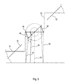
- the figure 5 illustrates in a pictorial way, the imperfections related to the cutting into subnets, and how it is possible to correct these imperfections through the cluster structure of the antenna according to the invention.
- This illustration represents an enlarged partial view of the illustration of an antenna composed of subnetworks as shown in FIG. figure 2 .
- the bearings 51 represent the phase planes of the different sub-networks that make up the antenna
- the line segments 52 are the orientation of the same phase planes to form a beam without lobes networks in a given direction. This direction is symbolized by the arrows 52. Since the orientation of the overall phase plane of the antenna is represented by the line 23, it can be seen that the positioning of the phase planes of the different sub-networks represents only an approximation. .
- This positioning is achieved by applying to each signal from a T / R modulates a same phase shift ⁇ re represented by the vectors 53.
- the signals thus phase shifted are then summed to form the receiving path of the considered subnet.
- the resulting approximation is responsible for the appearance of lattice lobes.
- the antenna according to the invention makes it possible to correct the imperfections of the signal obtained.
- the cluster provides a correction signal developed by performing a weighted sum of the signals from the T / R modules that compose it.
- an elementary corrective signal is thus obtained that makes it possible to compensate for the difference ⁇ existing between the phase shift actually applied to the modulating T / R and the theoretical phase shift enabling a beam devoid of lobes to be obtained.
- the correction signals are illustrated on the figure 5 in the form of vectors 56.
- the elementary corrective signals corresponding to the same beam F i are summed so as to constitute a corrective signal sum c Fn .
- information is available to form beams without network lobes.
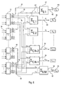
- the figure 6 schematically shows an example of complete structure of the antenna according to the invention.
- the outputs 34 of the T / R modules are distributed over different clusters 31.
- the outputs 43 of several clusters forming the same sub-network are applied to the inputs of a summing circuit 61 so as to produce, from the signals s 0.i from each cluster of the sub-network, a signal 62 corresponding to the signal S 0.r received by the sub-network r in the direction of the beam F 0 perpendicular to the phase plane of the antenna.
- the outputs 45 of all the clusters corresponding to the same beam are applied to the inputs of a summing circuit 63 of in order to obtain, from the signals c nk from each cluster, a corrective signal C n , 64.
- This signal makes it possible to reconstitute the signal received by the antenna in the direction of the beam F n .
- the structure therefore has as many summing circuits as there are sub-networks and beams to form.
- the outputs of the different summing circuits are then applied to receivers 65, integrated or not to the antenna, which perform the demodulation and digitization of the signals.
- the number of receivers required here is advantageously equal to the sum of the number of sub-networks constituting the antenna and the number of beams formed minus one.
- the beamforming by the calculation is here performed almost conventionally by calculating the matrix W correction coefficients to be applied to the signal from each sub-network.
- ⁇ 0 corresponds to the direction vector which defines the overall phase shift to be applied to the signals coming from the different sub-networks.
- ⁇ 0 characterizing a conventional sub-network antenna, in that it has as many lines as sub-networks and an additional line relating to the correction. corresponding to the beam considered.
- ⁇ 0 can be written: e j ⁇ 0 0 e 2 ⁇ j ⁇ 0 0 0 0 0 0 0 0 e mj ⁇ 0 0 1
- R x represents the covariance matrix of the signal composed of the signals coming from the different sub-networks and the correction signal relating to the beam considered.
- R x -1 has one more line than in the case of a conventional sub-array antenna. In the absence of jammers the matrix R x -1 corresponds to a unit matrix. It therefore appears possible to produce from the antenna according to the invention a multibeam antenna whose beams are advantageously devoid of network lobes.
- Such an antenna has the advantage of requiring only a reduced number of additional receivers compared to a conventional multibeam antenna having the same number of sub-networks.
- the number of additional receivers is for example equal to N-1.
- the formation of the beam F 0 is performed by summing the signals S 0.r from the different sub-networks. The sum of the different signals S 0.r constitutes the global signal S 0 .
- the formation of the other beams F n is carried out by performing the correction of the signal S 0 corresponding to the beam F 0 by the corrector signal C n relating to the beam F n .
Landscapes
- Engineering & Computer Science (AREA)
- Radar, Positioning & Navigation (AREA)
- Remote Sensing (AREA)
- Computer Networks & Wireless Communication (AREA)
- Physics & Mathematics (AREA)
- General Physics & Mathematics (AREA)
- Variable-Direction Aerials And Aerial Arrays (AREA)
Claims (6)
- Mehrfachstrahlantenne mit Strahlformung durch Berechnung, die das Formen von N Strahlen ermöglicht, die innerhalb von Clustern (31) zusammengefasste T/R-Module, wobei die Cluster in Elementarantennen bildenden Teilgittern zusammengefasst sind, und Mittel (41) aufweist, um an einem Ausgang (43) des Clusters ein Signal s0.k zu liefern, das gleich der Summe der von den im Cluster zusammengefassten T/R-Modulen stammenden Signale ist, wobei dieses Summensignal dem Signal entspricht, das von dem Cluster in Richtung des Strahls F0 lotrecht zur Phasenebene der Antenne empfangen wird,
dadurch gekennzeichnet, dass jeder Cluster k außerdem Mittel (44) aufweist, um an N-1 Ausgängen (45) N-1 Korrektursignale cn.k zu liefern; wobei jedes Korrektursignal einem gegebenen Strahl Fn entspricht und gleich der Summe von elementaren Korrektursignalen ist, wobei ein elementares Korrektursignal einem T/R-Modul zugeordnet ist und der Differenz zwischen dem tatsächlich von dem T/R-Modul empfangenen Signal (42) und dem Signal entspricht, das theoretisch empfangen würde, wenn die Phasenebene des T/R-Moduls im rechten Winkel zur Richtung des betrachteten Strahls Fn wäre, wobei das Korrektursignal cn.k es ermöglicht, das vom Cluster empfangene Signal in der Richtung zu konstruieren, die einem Strahl Fn entspricht, der sich vom Strahl F0 unterscheidet. - Antenne nach Anspruch 1, dadurch gekennzeichnet, dass jedes elementare Korrektursignal durch Multiplizieren des von jedem T/R-Modul empfangenen Signals (42) mit einem Gewichtungskoeffizient erhalten wird, der einen Amplitudenterm und einen Phasenterm hat.
- Antenne nach Anspruch 1, dadurch gekennzeichnet, dass das Korrektursignal cn.k bezüglich eines Strahls Fn es ermöglicht, die Differenz Δϕ zu kompensieren, die zwischen der tatsächlich an die T/R-Module angewendeten Phasenverschiebung (53) und der theoretischen Phasenverschiebung (54) existiert, die an jedes T/R-Modul angewendet werden muss, um einen Strahl Fn zu erhalten, der keine Gittervorsprung aufweist.
- Antenne nach einem der Ansprüche 1 oder 2, dadurch gekennzeichnet, dass sie für jedes Teilgitter m eine Summierschaltung (61) aufweist, die die Summe der Signale s0.k bildet, die von den Clustern stammen, die dieses Teilgitter m bilden, um das Signal S0.m (62) zu formen, das von dem Teilgitter m in Richtung des Strahls F0 empfangen wird, und dass sie für jeden Strahl Fn eine Summierschaltung (63) aufweist, die die Summe der Signale cn.k bildet, die von der Gesamtheit der Cluster stammen, um das globale Korrektursignal Cn (64) zu formen, das es ermöglicht, das Signal Sn zu konstruieren, das von der globalen Antenne in Richtung eines Strahls Fn ausgehend von dem Signal S0 empfangen wird, das von der globalen Antenne in Richtung des Strahls F0 empfangen wird.
- Antenne nach einem der vorhergehenden Ansprüche, dadurch gekennzeichnet, dass das Formen eines Strahls durch digitale Verarbeitung nach dem Empfang und der Codierung der Signale S0.m (62) und Cn (64) durch Empfangsschaltungen (65) durchgeführt wird.
- Antenne nach dem vorhergehenden Anspruch, dadurch gekennzeichnet, dass, wenn M die Anzahl von die Antenne bildenden Teilgittern ist, die Anzahl von Empfängern (65), die zum Formen der N Strahlen verwendet werden, gleich M + N - 1 ist.
Applications Claiming Priority (2)
| Application Number | Priority Date | Filing Date | Title |
|---|---|---|---|
| FR0313493A FR2862440B1 (fr) | 2003-11-18 | 2003-11-18 | Architecture d'antenne adaptative multifaisceaux a formation de faisceaux par le calcul |
| FR0313493 | 2003-11-18 |
Publications (2)
| Publication Number | Publication Date |
|---|---|
| EP1533866A1 EP1533866A1 (de) | 2005-05-25 |
| EP1533866B1 true EP1533866B1 (de) | 2008-10-01 |
Family
ID=34430013
Family Applications (1)
| Application Number | Title | Priority Date | Filing Date |
|---|---|---|---|
| EP20040104960 Expired - Lifetime EP1533866B1 (de) | 2003-11-18 | 2004-10-11 | Adaptive Phasengesteuerte Gruppenantenne mit digitaler Keulenformung |
Country Status (3)
| Country | Link |
|---|---|
| EP (1) | EP1533866B1 (de) |
| DE (1) | DE602004016808D1 (de) |
| FR (1) | FR2862440B1 (de) |
Cited By (1)
| Publication number | Priority date | Publication date | Assignee | Title |
|---|---|---|---|---|
| CN109324322A (zh) * | 2018-10-31 | 2019-02-12 | 中国运载火箭技术研究院 | 一种基于被动相控阵天线的测向与目标识别方法 |
Families Citing this family (7)
| Publication number | Priority date | Publication date | Assignee | Title |
|---|---|---|---|---|
| FR2864710B1 (fr) | 2003-12-24 | 2006-03-24 | Thales Sa | Procede d'optimisation de la definition d'une structure d' antenne ffc multifaisceaux a sous-reseaux imbriques |
| WO2007023371A1 (en) * | 2005-08-24 | 2007-03-01 | Reutech Radar Systems (Proprietary) Limited | Grating lobe assisted search radar system utilising antenna with multiple elements |
| WO2012056357A1 (en) * | 2010-10-28 | 2012-05-03 | Koninklijke Philips Electronics N.V. | System and method for presence detection |
| CN102142609A (zh) * | 2010-12-16 | 2011-08-03 | 哈尔滨工业大学 | 具有低旁瓣特性的子阵级自适应数字波束形成器 |
| FR3058227B1 (fr) * | 2016-10-27 | 2018-11-02 | Thales | Radar fmcw multifaisceaux, notamment pour automobile |
| US10520597B2 (en) * | 2016-12-09 | 2019-12-31 | Honeywell International Inc. | Aircraft radar system for bird and bat strike avoidance |
| US11079489B2 (en) | 2017-02-28 | 2021-08-03 | Honeywell International Inc. | Weather radar detection of objects |
Family Cites Families (1)
| Publication number | Priority date | Publication date | Assignee | Title |
|---|---|---|---|---|
| FR2838244B1 (fr) * | 2002-04-05 | 2006-05-19 | Thales Sa | Antenne adaptative multifaisceaux a formation de faisceaux par le calcul et radar comportant une telle antenne |
-
2003
- 2003-11-18 FR FR0313493A patent/FR2862440B1/fr not_active Expired - Fee Related
-
2004
- 2004-10-11 EP EP20040104960 patent/EP1533866B1/de not_active Expired - Lifetime
- 2004-10-11 DE DE200460016808 patent/DE602004016808D1/de not_active Expired - Lifetime
Cited By (1)
| Publication number | Priority date | Publication date | Assignee | Title |
|---|---|---|---|---|
| CN109324322A (zh) * | 2018-10-31 | 2019-02-12 | 中国运载火箭技术研究院 | 一种基于被动相控阵天线的测向与目标识别方法 |
Also Published As
| Publication number | Publication date |
|---|---|
| FR2862440A1 (fr) | 2005-05-20 |
| DE602004016808D1 (de) | 2008-11-13 |
| EP1533866A1 (de) | 2005-05-25 |
| FR2862440B1 (fr) | 2005-12-30 |
Similar Documents
| Publication | Publication Date | Title |
|---|---|---|
| EP2194602B1 (de) | Antenne mit gemeinsam benützten Elementarstrahlern und Verfahren zum Entwurf einer Mehrstrahlantenne mit gemeinsam benützten Elementarstrahlern | |
| EP0014650B1 (de) | Adaptives Höchstfrequenz-Raumfilter und dessen Verfahren der Anwendung zur Abschwächung oder Unterdrückung der Nebenzipfel des Strahlungsdiagrammes einer Antenne | |
| EP2434310B1 (de) | Radar mit großer Winkelabdeckung an Bord von Flugzeugen mit Autopilot, insbesondere zum Ausweichen von Hindernissen | |
| CA2134055A1 (fr) | Antenne a reseau d'elements rayonnants | |
| EP3503431B1 (de) | Verfahren zur mehrfachstrahlabdeckung durch gruppieren von elementarstrahlen derselben farbe, und nutzlast von telekommunikationsvorgängen zur umsetzung dieses verfahrens | |
| EP0462864B1 (de) | Vorrichtung zur Speisung von Strahlungselementen einer Gruppenantenne und ihre Verwendung für eine Antenne eines Landungshilfssystems vom Typ MLS | |
| WO2018141852A1 (fr) | Antenne elementaire a dispositif rayonnant planaire | |
| FR3076137B1 (fr) | Procede de couverture multifaisceaux par regroupement de faisceaux elementaires de couleurs differentes, et charge utile de telecommunications pour mettre en oeuvre un tel procede | |
| CA2821250A1 (fr) | Antenne d'emission et de reception multifaisceaux a plusieurs sources par faisceau, systeme d'antennes et systeme de telecommunication par satellite comportant une telle antenne | |
| EP1955405B1 (de) | Array-antenne mit irregulärem netz und potentieller kälteredundanz | |
| FR2806214A1 (fr) | Antenne reflectrice comportant une pluralite de panneaux | |
| EP1533866B1 (de) | Adaptive Phasengesteuerte Gruppenantenne mit digitaler Keulenformung | |
| EP0451497B1 (de) | Verfahren zur Formung des Strahlendiagrammes einer aktiven Radarantenne mit elektronisch gesteuerter Ablenkung, und Antenne dazu | |
| EP3159965B1 (de) | Antennennetzsender für ein monoimpulsradarsystem | |
| FR2792116A1 (fr) | Formation numerique de faisceaux | |
| EP1351333A2 (de) | Adaptive Gruppenantenne und Radar mit einer solchen Antenne | |
| EP3945636B1 (de) | Verfahren zur veränderung des strahlungsdiagramms eines antennennetzes und radar zur umsetzung eines solchen verfahrens | |
| CA2356725A1 (fr) | Lentille divergente a dome pour ondes hyperfrequences et antenne comportant une telle lentille | |
| EP3155689B1 (de) | Flachantenne zur satellitenkommunikation | |
| EP1233282B1 (de) | Vorrichtung mit verteilten Sende- und Empfangsantennen, insbesondere für Radar mit synthetischer Emission und Strahlbildung | |
| EP1107359A1 (de) | Strahlungsquelle für eine Sende-/Empfangsantenne an Bord eines Satelliten | |
| FR2773269A1 (fr) | Dispositif large bande de detection, notamment de radars | |
| WO2025163550A1 (fr) | Antenne à source défocalisée | |
| EP3326240A1 (de) | Verbesserte elektronische abtastantenne mit unmittelbarem breitfrequenzband | |
| WO2021008977A1 (fr) | Antenne reseau multi-panneaux |
Legal Events
| Date | Code | Title | Description |
|---|---|---|---|
| PUAI | Public reference made under article 153(3) epc to a published international application that has entered the european phase |
Free format text: ORIGINAL CODE: 0009012 |
|
| AK | Designated contracting states |
Kind code of ref document: A1 Designated state(s): AT BE BG CH CY CZ DE DK EE ES FI FR GB GR HU IE IT LI LU MC NL PL PT RO SE SI SK TR |
|
| AX | Request for extension of the european patent |
Extension state: AL HR LT LV MK |
|
| AKX | Designation fees paid | ||
| 17P | Request for examination filed |
Effective date: 20050811 |
|
| RBV | Designated contracting states (corrected) |
Designated state(s): DE GB IT NL |
|
| REG | Reference to a national code |
Ref country code: DE Ref legal event code: 8566 |
|
| GRAP | Despatch of communication of intention to grant a patent |
Free format text: ORIGINAL CODE: EPIDOSNIGR1 |
|
| GRAS | Grant fee paid |
Free format text: ORIGINAL CODE: EPIDOSNIGR3 |
|
| GRAA | (expected) grant |
Free format text: ORIGINAL CODE: 0009210 |
|
| AK | Designated contracting states |
Kind code of ref document: B1 Designated state(s): DE GB IT NL |
|
| REG | Reference to a national code |
Ref country code: GB Ref legal event code: FG4D Free format text: NOT ENGLISH |
|
| REF | Corresponds to: |
Ref document number: 602004016808 Country of ref document: DE Date of ref document: 20081113 Kind code of ref document: P |
|
| PLBE | No opposition filed within time limit |
Free format text: ORIGINAL CODE: 0009261 |
|
| STAA | Information on the status of an ep patent application or granted ep patent |
Free format text: STATUS: NO OPPOSITION FILED WITHIN TIME LIMIT |
|
| 26N | No opposition filed |
Effective date: 20090702 |
|
| PGFP | Annual fee paid to national office [announced via postgrant information from national office to epo] |
Ref country code: NL Payment date: 20101009 Year of fee payment: 7 |
|
| PGFP | Annual fee paid to national office [announced via postgrant information from national office to epo] |
Ref country code: DE Payment date: 20101006 Year of fee payment: 7 |
|
| PGFP | Annual fee paid to national office [announced via postgrant information from national office to epo] |
Ref country code: IT Payment date: 20101020 Year of fee payment: 7 Ref country code: GB Payment date: 20101006 Year of fee payment: 7 |
|
| REG | Reference to a national code |
Ref country code: NL Ref legal event code: V1 Effective date: 20120501 |
|
| GBPC | Gb: european patent ceased through non-payment of renewal fee |
Effective date: 20111011 |
|
| PG25 | Lapsed in a contracting state [announced via postgrant information from national office to epo] |
Ref country code: NL Free format text: LAPSE BECAUSE OF NON-PAYMENT OF DUE FEES Effective date: 20120501 Ref country code: DE Free format text: LAPSE BECAUSE OF NON-PAYMENT OF DUE FEES Effective date: 20120501 |
|
| REG | Reference to a national code |
Ref country code: DE Ref legal event code: R119 Ref document number: 602004016808 Country of ref document: DE Effective date: 20120501 |
|
| PG25 | Lapsed in a contracting state [announced via postgrant information from national office to epo] |
Ref country code: IT Free format text: LAPSE BECAUSE OF NON-PAYMENT OF DUE FEES Effective date: 20111011 Ref country code: GB Free format text: LAPSE BECAUSE OF NON-PAYMENT OF DUE FEES Effective date: 20111011 |