TECHNICAL FIELD
The present invention relates to a monitoring system to
monitor remotely, via a communication network, various equipment
such as clinical laboratory test equipment for predicting e.g.
equipment failures.
BACKGROUND ART
In the case where a failure occurs in a machine or the like, a
trouble shooting manual and a service manual (hereafter, collectively
referred to as simply manual) are used for determining causes of the
failure and repair methods, depending on the failure symptoms. For
quickly restoring the machine or the like from failures, it is
important whether items to examine causes of failures are arranged
in a proper order in a manual or not. For example, with respect to a
certain failure symptom, if causes that develop this symptom more
frequently are described earlier in a reference order in the manual, it
is possible to shorten the time required for a user or a service
engineer of the equipment to find the causes of the failure, enabling
quick recovery.
Accordingly, it is preferable that among causes of failures
presumable from failure symptoms, such causes of failures as having
higher probabilities together with repair procedures effective for
such causes of failures are so described in the manual as to be
arranged with priority in the manual. Conversely, a manual that is
not described in such manner has a problem in that it takes a long
time to determine causes of failures. Assume the case, for example,
where check items not directly relevant to determine causes of
failures are described with priority in a manual, and moreover where
procedures to implement the checking are complicated and require
much time. Considering that many service engineers do repair work
using the manual in such case, an overall waste of time becomes too
much to ignore.
In order to update manuals, however, a lot of labor and time
are needed. Thus, conventionally, manuals generally are updated
only in cases where they become non-functional as manuals unless
they are updated, such as in the case where equipment specifications
have been subjected to major changes. In other words, in the case of
minor changes, manuals are sometimes not updated. Besides,
updating of documents for new equipment models requires much time
and manual work.
DISCLOSURE OF THE INVENTION
The present invention has thus been made to solve such
problem. Its object is to realize a support system for trouble
handling that can provide an online manual that enables efficient
determination of causes of failures and does not require laborious
work for updating.
For achieving the above-described object, a support system
for trouble handling according to the present invention includes: a
diagnostic path storage unit to store a list of event data of troubles
capable of occurring in an equipment, a list of data of diagnostic
material for determining causes of the events, and a list of handling
procedure data corresponding to the causes, and further store
interrelations among these data; a diagnostic material presentation
unit to receive event data input thereto, and to extract, from the
diagnostic path storage unit, data of diagnostic material relating to
the event data input thereto, and further to output the extracted
data of diagnostic material; and a handling procedure presentation
unit to receive some of the data of diagnostic material output by the
diagnostic material presentation unit and selectively input thereto,
and to extract, from the diagnostic path storage unit, handling
procedure data relating to such cause as determined by the data of
diagnostic material selectively input thereto, and further to output
the extracted handling procedure data, wherein the data of
diagnostic material for respective event data are stored in the
diagnostic path storage unit with closeness-of-fit added thereto, and
wherein the diagnostic material presentation unit outputs the
extracted data of diagnostic material in order according to the
closeness-of-fit.
It is to be noted here that "closeness-of-fit" of diagnostic
material is used to mean the number of times or frequency at which
the diagnostic material has served as a decisive factor for
determining causes of an event. Furthermore, an expression "data
of diagnostic material are stored according to closeness-of-fit" is used
to cover both: a mode where the data of diagnostic material are
stored together with data obtained by quantifying the
closeness-of-fit; and a mode where the data of diagnostic material are
arranged in a storage area in order according to the closeness-of-fit.
This configuration realizes that when event data of trouble is
input, data of diagnostic material to determine its causes are output
in order according to the closeness-of-fit. Thus, a person handling
the trouble can determine the causes of the trouble more efficiently.
Preferably, the support system for trouble handling further
includes: an actual result storage unit in which event data of troubles,
data of diagnostic material having been selected in determining
causes of the troubles, and handling procedure data of procedures
having been performed to handle the troubles are stored as actual
cases of troubles; and a closeness-of-fit decision unit to perform a
process of deciding closeness-of-fit of data of diagnostic data material
to each one of the event data according to the number of times or
frequency at which each one of the data of diagnostic material has
been selected among the cases of troubles stored in the actual result
storage unit.
This configuration realizes that the closeness-of-fit of the
data of diagnostic material to each of the event data is decided
according to the number of times or frequency at which each one of
the data of diagnostic material has been selected among the cases of
troubles stored in the actual result storage unit. Thus, maintenance
can be performed automatically to present handling procedures
according to the closeness-of-fit of the data of diagnostic material,
without requiring the laborious work of updating.
Preferably, the diagnostic path storage unit in the support
system for trouble handling further stores therein data to decide
degrees of priority of the handling procedure data for the respective
ones of the causes, wherein according to the degrees of priority, the
handling procedure presentation unit presents the handling
procedure data extracted from the diagnostic path storage unit.
Preferably, the diagnostic path storage unit stores, as the
data to decide the degrees of priority, at least one of: time required
for each handling procedure; cost required to perform each handling
procedure; and average time from after each handling procedure has
been performed until the same event occurs due to the same cause in
the same equipment.
It is also possible to allow a user to input selection to select
which of the data to decide the degrees of priority, using, as the data
to decide the degrees of priority, at least two of: (1) time required for
each handling procedure; (2) cost required to perform each handling
procedure; and (3) time from after each handling procedure has been
performed until the same event occurs due to the same cause in the
same equipment.
Preferably, the handling procedure data in the support
system for trouble handling contains action content to describe
individual actions.
Also preferably, the support system for trouble handling
further includes: an input unit to selectively or optionally input a
combination of the event data, the data of diagnostic material and
the handling procedure data; and a new path registration unit to
interrelate and store, in the diagnostic path storage unit, the event
data, the data of diagnostic material and the handling procedure
data that are input by the input unit.
This configuration makes it possible to store, at any time,
new combinations of the event data, the data of diagnostic material
and the handling procedure data. Thus, a support system for
trouble handling that does not require laborious work for
maintenance can be realized.
For achieving the above-described object, a terminal
according to the present invention is a terminal suitable to be
connected to any one of the above-described support systems for
trouble handling, and includes: an event input unit to input event
data of troubles occurring in an equipment; a diagnostic material
input unit to receive data of diagnostic material output by the
diagnostic material presentation unit and to selectively input some of
data of diagnostic material as selected from the received data of
diagnostic material; and a handling procedure display unit to receive
handling procedure data output by the handling procedure
presentation unit and to display the received handling procedure
data.
BRIEF DESCRIPTION OF THE DRAWINGS
FIG. 1 is a block diagram showing a schematic configuration
of a service support system and an SE terminal according to an
embodiment of the present invention.
FIG. 2A to FIG. 2D are explanatory charts showing examples
of data stored in the service support system.
FIG. 3A and FIG. 3B are explanatory charts showing
examples of data stored in the service support system.
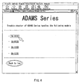
FIG. 4 is an example of a screen displayed when the SE
terminal is connected to the service support system.
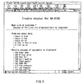
FIG. 5 is an example of a symptom selection screen displayed
on the SE terminal by the service support system.
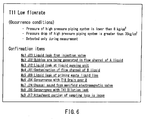
FIG. 6 is an example of a diagnostic material selection screen
displayed on the SE terminal by the service support system.
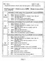
FIG. 7 is an example of a handling procedure selection screen
displayed on the SE terminal by the service support system.
FIG. 8 is an example of an action list screen displayed on the
SE terminal by the service support system.
FIG. 9 is an example of a screen, explaining an action,
displayed on the SE terminal by the service support system.
FIG. 10 is an example of a repair report input screen.
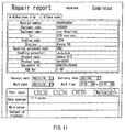
FIG. 11 is an example of a repair report input screen for a
service engineer to register a new path on.
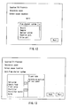
FIG. 12 is an example of a screen, displayed on the SE
terminal subsequently to the screen of FIG. 11, for a service engineer
to register a new path on.
FIG. 13 is an example of a screen displayed on the SE
terminal subsequently to the screen of FIG. 12.
FIG. 14 is an example of a screen displayed on the SE
terminal subsequently to the screen of FIG. 13.
FIG. 15 is an example of a screen displayed on the SE
terminal subsequently to the screen of FIG. 14.
FIG. 16 is an example of a screen displayed on the SE
terminal subsequently to the screen of FIG. 15.
FIG. 17 is a block diagram showing a schematic configuration
of the SE terminal.
BEST MODE FOR CARRYING OUT THE INVENTION
Hereinafter, an embodiment of the present invention will be
described with reference to the drawings.
[Outline of Service Support System]
A service support system according to the present
embodiment is such a system as operated and managed by an
equipment maker for supporting service engineers to, e.g., repair and
maintain equipment supplied to users (hereafter referred to as user
equipment).
Hence, as shown in FIG. 1, a service support system 1
according to the present embodiment is connected, via internet 30, to
SE terminals P1, P2 ··· (hereafter referred to as SE terminal P) which
service engineers carry. An optional portable type terminal having
connectability to the Internet, such as personal computer, PDA or
cellular phone, can be used for the SE terminal P. In order to do
repair or maintenance work, a service engineer connects an SE
terminal P, which the service engineer carries, to the service support
system 1 via the internet 30, and does the work according to an
online manual provided by the service support system 1 to the SE
terminal P.
For doing repair work, the service engineer first inputs a
failure symptom of the user equipment to the SE terminal P. Since
the same failure symptom often is caused by various causes, it is
important to determine causes of the failure correctly and quickly in
order to repair the failure properly and efficiently. For each of the
expectable failures in each of various kinds of user equipment,
symptoms and their causes together with diagnostic material to
determine the causes by the symptoms are interrelated and stored in
a database in the service support system 1. When the service
engineer inputs a symptom to the SE terminal P, the service support
system 1 selects candidates of diagnostic material considered to be
effective for determining the causes, and displays the candidates in
the proper order of priority on a display of the SE terminal P. This
order of priority (closeness-of-fit) of the diagnostic material is
decided by the service support system 1 on the basis of accumulated
cases of handling failures, and is updated appropriately when new
cases of handling are accumulated, as will be described later.
The service engineer determines the causes of the failure by
doing confirmation work, in order of priority from high to low, on the
diagnostic material displayed on the SE terminal P. After the
causes are determined, the service support system 1 selects, from the
database, descriptions of handling processes fit for the causes, and
displays the descriptions in proper order of priority on the display of
the SE terminal P. Thereby, the service engineer can proceed with
the work, as the service engineer watches the descriptions displayed
on the display of the SE terminal P. Thus, the service engineer can
do the repair or maintenance work properly and efficiently.
After the repair work, the service engineer prepares a repair
report on the SE terminal P. For this report, information is input
such as: information about the user (e.g. user name); information
about the failed user equipment (e.g. model name and equipment ID);
the symptoms of the failure; the diagnostic material having served as
a decisive factor for determining the causes; and information about
e.g. the handling work done. The information input to the repair
report by the service engineer is sent from the SE terminal P to the
service support system 1. Based on this information, the service
support system updates the database storing the diagnostic material,
and also updates the order of priority of the diagnostic material and
the handling procedure.
[Configuration of Service Support System]
Here, an example of configuration of the service support
system 1 will be described with reference to FIG. 1 and FIG. 2. As
shown in FIG. 1, the service support system 1 includes: a data
storage unit 10 having a handling procedure-to-action
correspondence data storage unit 11, an action data storage unit 12, a
content storage unit 13, a repair report data storage unit 14 (actual
result storage unit), an evaluation data storage unit 15, a diagnostic
path data storage unit 16 (diagnostic path storage unit), a
cause-to-handling procedure correspondence data storage unit 17, a
user equipment information master file 18, and so on; a
communication processing unit 19; a data extraction unit 20
(diagnostic material presentation unit / handling procedure
presentation unit), an update processing unit 21 (closeness-of-fit
decision unit / new path registration unit); and so on.
For each of user equipment models, as shown in FIG. 2A,
codes of trouble handling procedures and codes of one or plural
actions to compose each trouble handling procedure are recorded in
the handling procedure-to-action correspondence data storage unit 11,
with both codes being interrelated with each other. Action is a unit
of work done by a service engineer, such as "confirm", "exchange",
"adjust" or the like. Each action is not necessarily composed of a
single operation, but can include a series of operations. For
example, an action "to exchange a seal" includes not only an
operation to exchange a seal, but also an accompanying operation
such as "to take off a cover (at the location of the seal to be
exchanged)". In the case of the example shown in FIG. 2A, one
trouble handling procedure SR0302 for an equipment model HA-8160
is composed of four actions A011, A239, A021 and A012.
As to all actions for each user equipment, as shown in FIG.
2B, action numbers, time required for each action, price of parts
needed for each action, and hyperlink to action content corresponding
to each action are recorded in the action data storage unit 12, with
these data being interrelated with each other. Action content is
content for displaying a detailed description of the action on the SE
terminal P in order for a service engineer to be able to refer to in the
repair work, and is recorded in the content storage unit 13 as e.g. a
file in HTML format or the like.
As shown in FIG. 2C, data of repair reports prepared by
respective service engineers, after completion of the repair work, are
recorded in the repair report data storage unit 14, with the data
being interrelated with each other, wherein examples of such data
are report number, model number of repaired user equipment,
equipment ID of the user equipment, work date, code of failure
symptom, code of diagnostic material having served as a decisive
factor for determining cause, code of determined cause of failure,
code of handling procedure having been referenced in repair work,
and so on.
As shown in FIG. 2D, information to evaluate the order of
priority of handling procedures for failures of respective equipment
models is recorded in the evaluation data storage unit 15, the
information being e.g. cause-based MTBF, MTBF, calculation
completion report number, MTTR, cost and so on. MTBF means an
average value of time from the time one failure occurs to the time the
next failure occurs. On the other hand, unlike ordinary MTBF,
"cause-based MTBF" represents an average value of time from the
time one failure occurs to the time another failure based on the same
cause occurs again. It is to be noted that the data recorded in the
evaluation data storage unit 15 are updated appropriately by the
update processing unit 21 on the basis of content in the repair report
data storage unit 14, as will be described in detail later.
For each model of user equipment, as shown in FIG. 3A, the
diagnostic path data storage unit 16 (diagnostic path storage unit)
stores relations among symptom code, diagnostic material code and
cause code, which is determined by the combination of symptom and
diagnostic material. For instance, in the example shown in FIG. 3A,
when "J23" is selected as a diagnostic material in the case where the
symptom code for HA-8160 is "T11", then the cause code of the failure
is determined as "R01". Note that records in the diagnostic path
data storage unit 16 are sorted in order of equipment model names,
and further that records for the same equipment model name are
sorted in order of the symptom codes. In addition, records for the
same symptom code are sorted by the diagnostic material code in
order of such number of actual results, from large to small, that the
diagnostic material codes have been used to determine causes of the
symptom. More specifically, the example shown in FIG. 3A indicates
that in the records with equipment model name "HA-8160" and
symptom code "T11", the diagnostic material code "J23" has been the
most frequently used, with "J02" having been the second most
frequently used, as a decisive factor for determining causes in past
repair cases. It is to be noted that the order of the diagnostic
material codes in the diagnostic path data storage unit 16 is updated
at predetermined timings by the update processing unit 21 on the
basis of data accumulated in the repair report data storage unit 14,
as will be described later.
For each model of user equipment, as shown in FIG. 3B, the
cause-to-handling procedure correspondence data storage unit 17
stores relations between cause code and handling procedure code.
For instance, the example of FIG. 3B indicates that with respect to
HA-8160, four kinds of trouble handling procedures "SR0302",
"SR0201", "SR0408" and "SR0409" exist when the cause of the trouble
is determined as "R02".
The user equipment information master file 18 stores all
warning messages which user equipment output. It also stores
information about parts constituting the user equipment, and so on.
The communication processing unit 19 controls, via the
internet 30, communication with external devices such as the SE
terminal P. The data extraction unit 20 (diagnostic material
presentation unit / handling procedure presentation unit) extracts
data from respective units of the data storage unit 10 in accordance
with predetermined conditions. The update processing unit 21
updates the order of priority of the diagnostic material, and so on.
[Operation of Service Support System]
Taking, as an example, the case of a failure of a user
equipment (model name: HA-8160), the operations of the service
support system 1 and the SE terminal P will be described specifically.
When a service engineer receives a communication from an
equipment user and arrives at the user, the service engineer connects
the SE terminal P to the service support system 1 via the Internet 30.
Thereby, as shown in FIG. 4, e.g., a screen (equipment model
selection screen) to selectively input a model name of a user
equipment is displayed on the display of the SE terminal P. When
the service engineer here selects the model name of the user
equipment to be repaired as shown in FIG. 4, the selected model code
is sent to the data extraction unit 20 via the communication
processing unit 19 in the service support system 1. In accordance
with the model code, the data extraction unit 20 extracts, from the
content storage unit 13, content of a screen (symptom selection
screen) to selectively input a symptom from a list of expectable
troubles concerning the equipment model as shown in FIG 5, for
example. The extracted content is transferred to the communication
processing unit 19, and is then sent to the SE terminal P. Thus, a
screen such as shown in FIG. 5 is displayed on the display of the SE
terminal P.
On the symptom selection screen displayed on the SE
terminal, the service engineer selects a symptom that agrees with the
symptom of the user equipment. It is assumed here that a trouble
message "T11 Low flowrate" is displayed on the user equipment to be
repaired, and that the service engineer has selected the "T11···" on
the symptom selection screen as shown in FIG. 5. The codes (Dxx,
Exx, Txx and so on) each shown at the beginning of each symptom on
the screen are symptom codes individually assigned to respective
trouble symptoms. When the service engineer selects one of the
symptoms, the symptom code is sent from the SE terminal P to the
service support system 1.
When the service support system 1 receives the symptom code
sent from the SE terminal P, the data extraction unit 20 extracts
diagnostic material codes for determining causes of the symptom by
referencing the diagnostic path data storage unit 16, using the
received symptom code as a key. As described above, the diagnostic
path data storage unit 16 stores diagnostic materials in order of such
number of times, from large to small, that the diagnostic materials
have served as decisive factors for determining causes of each
symptom in past repair cases. The data extraction unit 20 sends the
diagnostic material codes, having been extracted from the diagnostic
path data storage unit 16, to the SE terminal P according to such
order of priority. Thus, such screen (diagnostic material selection
screen) as shown in e.g. FIG. 6 that displays diagnostic material,
with the provided order of priority for determining the causes of the
failure from the symptom is displayed on the display of the SE
terminal P. In the example shown in FIG. 6, diagnostic material for
determining causes of the trouble ("T11") are displayed with the
order of priority (No. 1 etc.) being provided thereto. In FIG. 6, codes
(Jxx) each shown after each order of priority are diagnostic material
codes individually assigned to respective diagnostic material. Note
that in FIG. 6 and later described FIG. 7 and FIG. 8, browser frames
and the like are omitted in the drawing.
The service engineer confirms the diagnostic materials
(confirmation items), in the order of priority from high to low, that
are displayed on the diagnostic material selection screen. More
specifically, in the example of FIG. 6, the service engineer first
confirms whether or not there is liquid leak from an injection valve
(No. 1 J23). If there is no liquid leak, the service engineer next
confirms whether bubbles are being generated in flow channel of A
liquid (No. 2 J02). If bubbles are found to be generated, the service
engineer selects this confirmation item (No. 2 J02) on the diagnostic
material selection screen. Thereby, the selected diagnostic material
code is sent from the SE terminal P to the service support system 1.
When the service support system 1 receives the diagnostic
material code sent from the SE terminal P, the data extraction unit
20 determines the cause by referencing the diagnostic path data
storage unit 16, using the model name of the user equipment, the
symptom code and the diagnostic material code as keys. For
instance, assuming in the above case that data as shown in FIG. 3A
are stored in the diagnostic path data storage unit 16, the cause code
to be determined is "R02" since the equipment model name is
"HA-8160", the symptom code is "T11", and the diagnostic material is
"J02".
After determining the cause code, the data extraction unit 20
references the cause-to-handling procedure correspondence data
storage unit 17 on the basis of this cause code, and extracts a
handling procedure to handle the cause. For instance, if the cause
code is "R02" in the case where the content of the cause-to-handling
procedure correspondence data storage unit 17 is such data as shown
in FIG. 3B, then four kinds of handling procedures "SR0302",
"SR0201", "SR0408" and "SR0409" are extracted.
The data extraction unit 20 further extracts, from the
handling procedure-to-action correspondence data storage unit 11
and the action data storage unit 12, information about actions
constituting respective handling procedures having been extracted.
The data extraction unit 20 furthermore extracts, from the
evaluation data storage unit 15, MTTRs of the respective handling
procedures having been extracted. And then, the data extraction
unit 20 provides the extracted handling procedures with the order of
priority in order of the MTTR values from small to large, and sends
the handling procedures to the SE terminal P. Thereby, as shown in
FIG. 7, such a screen (handling procedure selection screen) is
displayed on the display of the SE terminal P that handling
procedures to handle the cause "R02" are arranged in the order of
MTTR from small to large.
The handling procedure selection screen, as described above,
displays handling procedures that are determined by the selected
combination of a trouble event and diagnostic material. In the
example of FIG. 7, all handling procedures, which have been selected
by the service support system 1 from the combination of the trouble
event (event code "T11") selected on the event selection screen and
the diagnostic material (diagnostic material code "J02") selected on
the diagnostic material selection screen, are displayed with the order
of priority being provided thereto. Note that for displaying
handling procedures according to the present embodiment mode, it is
possible to select the order of priority from three kinds: (1) order of
MTTR from short to long; (2) order of MTBF from long to short; and
(3) order of repair cost from low to high. In the example of FIG. 7,
three handling procedures are displayed in the order of MTTR from
short to long. However, if the service engineer selects "Order of
MTBF" or "Order of cost", then the data extraction unit 20 references
the evaluation data storage unit 15 according to that selection, and
rearranges the handling procedures to be displayed. Although the
order of MTTR, from small to large, is used in this example to
initially display the handling procedure selection screen, it can also
be such that the order of MTBF or the order of cost is initially
displayed, and is rearranged according to the selection by the service
engineer.
Now, when the service engineer selects the handling
procedure "SR0302" which is displayed with top priority, the display
screen of the SE terminal P is changed to an action list screen to list
actions included in the selected handling procedure, e.g., as shown in
FIG. 8. Each of the actions displayed on the screen shown in FIG. 8
is provided with a link. When the service engineer selects an action
as shown in FIG. 8, action content corresponding to the action is
extracted from the content storage unit 13 by the link provided to the
selected action, and is displayed on the screen of the SE terminal P.
For instance, if the service engineer selects the action [A011] on the
screen shown in FIG. 8, then the screen display of the SE terminal P
is changed to such screen as shown in e.g. FIG. 9. The service
engineer does the repair work as the service engineer watches this
screen. Note that action content is designed such that it is possible,
depending on the need, to scroll a screen, enlarge a part of a screen,
and switch screens back-and-forth.
After the work is done, the service engineer calls a repair
report preparing screen on the SE terminal P as shown in FIG. 10,
and inputs the necessary items. It is to be noted that in FIG. 10 and
later described FIG. 11 to FIG. 16, browser frames and the like are
omitted in the drawing. On this screen, a path input column 40 is
provided. According to the above-described example, for instance:
"T11" has been selected on the event selection screen of FIG. 5; "J02"
has been selected on the diagnostic material selection screen of FIG.
6; and "SR0302" has been selected on the handling procedure
selection screen of FIG. 7. Thus, the service engineer inputs these
codes in the path input column 40, as shown in FIG. 10. The data
having been input in the path input column 40 together with other
data having been input to the repair report preparing screen are sent
from the SE terminal P to the service support system 1. In the
service support system 1, the update processing unit 21 stores the
repair report data sent from the SE terminal P in the repair report
data storage unit 14, as shown in e.g. FIG. 2C.
The foregoing is a description of the operations of the service
support system 1 and the SE terminal P for a service engineer to do
repair work.
[Update Processing in Data Storage Unit]
Based on the data stored in the repair report data storage
unit 14, the service support system 1 periodically updates: the order
of priority of the diagnostic material in the diagnostic path data
storage unit 16; and various data in the evaluation data storage unit
15. This updating process either can be performed at regular time
intervals such as once a day, once a month or the like, or performed
every time a predetermined number of new repair report data are
added to the repair report data storage unit 14.
As for the order of priority of the diagnostic material in the
diagnostic path data storage unit 16, the update processing unit 21
calculates, from all actual results of repair stored in the repair report
data storage unit 14, such respective numbers that respective
diagnostic material codes have been used for each same symptom in
each same equipment model. Based on the results of the calculation,
the update processing unit 21 rearranges the record in the diagnostic
path data storage unit 16 so as to arrange the diagnostic material for
each symptom in each equipment model in the order of the number of
times, from large to small, that the diagnostic material have served
as decisive factors for determining causes in actual results of past
repairs.
Furthermore, the update processing unit 21 updates content
in the evaluation data storage unit 15 on the basis of the data stored
in the repair report data storage unit 14. First, from records added
to the repair report data storage unit 14 after previous updating
process, the update processing unit 21 extracts records that agree
with each other as to all the equipment ID, the symptom and the
cause, and calculates intervals between work dates in such records.
For instance, in the example of FIG. 2C, the record of the report
number "123456" agrees with the record of the report number
"123452" as to all the equipment ID, the symptom and the cause.
Thus, the update processing unit 21 calculates the difference
between the date data recorded in the work date columns of these
records. In this case, the difference between March 26, 2002 and
March 12, 2002 is calculated to be 14 days. More specifically, it is
indicated that, 14 days after repair work was done according to the
handling procedure "SR0302" on March 12, 2002 for a failure of a
symptom due to a cause in a user equipment, a failure of the same
symptom due to the same cause occurred in the same user equipment.
Next, using this value, the update processing unit 21 updates the
value of the cause-based MTBF as to that equipment model name
(HA-8160) and that handling procedure (SR0302). In the example
shown in FIG. 2D, the value of the cause-based MTBF in the handling
procedure "SR0302" for HA-8160 is 193 days. However, by adding
the data of 14 days as calculated above:
(193×23+14)/(23+1) = 186
Based on this, the days of the cause-based MTBF, the number of
samples and the calculation completion report number are updated to
186, 24 and 123452, respectively.
According to the above process, the update processing unit 21
updates the order of priority of the diagnostic material, the values of
the cause-based MTBF, and the like at predetermined timings.
[Process of Newly Creating Diagnostic Path]
In the service support system 1 of the present embodiment, a
service engineer can add a new path to the diagnostic path data
storage unit 16 according to the following procedure. Assume a case,
for instance, where no appropriate diagnostic material has been
displayed when a service engineer has accessed the service support
system 1 from an SE terminal P for repairing a failure in a user
equipment, so that the service engineer, by himself, has handled it
appropriately. In such case, the service engineer can register, to the
service support system 1, the content of the work done himself.
Hereafter, this registration procedure will be described, using
a specific example. It is assumed here that a warning message "T11:
Low flowrate" has been displayed on a user equipment, and hence
that a service engineer has accessed the service support system 1
from an SE terminal P, but that no diagnostic material corresponding
to the symptom has been displayed. It is further assumed that when
the service engineer has then checked by himself, it has been found
that "Bubbles are being generated in flow channel of A liquid", and
that its cause is "Bad connection between eluant tube and rear panel".
It is furthermore assumed that for repairing this failure, the service
engineer has sequentially performed four actions: replacing of
replacement seal (action code: A011); retightening of connecting
portion between eluant tube and rear panel (A239); confirming of
piping pressure (A021); and confirming of measurement operation
(A012).
On the repair report preparing screen displayed on the SE
terminal as shown in FIG. 11, the service engineer first selects a
symptom in the path input column 40. Here, the symptom "T11:
Low flowrate" is selectively input. Note here that all warning
messages output by the user equipment are preliminarily registered
in the user equipment information master file 18 of the service
support system 1, so that a list of all the warning messages is
displayed in the path input column 40. Accordingly, the service
engineer can select an applicable one from the displayed list of
warning messages. However, it also can be so designed that
symptom codes and descriptions thereof for symptoms not registered
in the master file can be newly created. When the service engineer
presses "New Creation" button, the screen of the SE terminal P is
changed to a screen, as shown in FIG. 12, to fill in causes. Now, the
service engineer inputs location (name of unit) causing the failure.
Here, "Flow Channel System" is selected, and "Next" button is
pressed, whereby the screen of the SE terminal P is changed to a
screen as shown in FIG. 13.
On the screen shown in FIG. 13, parts of the flow channel
system are extracted from the user equipment information master
file 18, and are displayed as a list in a part list column 41. The
service engineer selects applicable parts from the list, and presses an
addition button 42 for addition to a cause location column. Here,
"Eluant tube" and "Connecting portion of rear panel" are selected and
added. The added parts are displayed in the cause location column
43.
When the service engineer presses "Next" button after the
determination of the cause location, the screen of the SE terminal is
changed to a screen as shown in FIG. 14. Now, the service engineer
selects factor (stress) having served as the cause. Here, "Bad
connection" is selected. When the service engineer presses the
"Next" button, the screen of the SE terminal is changed to a screen as
shown in FIG. 15.
Now, the service engineer inputs a diagnostic criterion for
determining causes, using an optional character string. It is to be
noted that considerations should be made here to make the input
diagnostic criterion objectively different from existing diagnostic
criteria. This is to allow other service engineers to be able to
understand differences among diagnostic criteria. In the example of
FIG. 15, the diagnostic criterion that the service engineer has input
is "Bubbles are being generated in flow channel of A liquid".
When the diagnostic criterion is input, the screen of the SE
terminal is changed to a screen as shown in FIG. 16. On this screen,
by the action numbers "A011", "A239", "A021" and "A012", the service
engineer inputs the content of the work done for repairing the
failure.
The information thus input by the service engineer is
registered by the update processing unit 21 in the diagnostic path
data storage unit 16, the cause-to-handling procedure
correspondence data storage unit 17 and the handling
procedure-to-action correspondence data storage unit 11, so as to
become usable by other service engineers.
Here, referring to FIG. 17, a schematic configuration of the
SE terminal P will be described. The SE terminal P is configured to
be an optional portable type terminal having internet connectability
as described above, and includes an event input support unit 51, a
diagnostic material input support unit 52 and a handling procedure
display unit 53 as shown in FIG. 17. The SE terminal P also
includes: a display 54 capable of displaying such screens as shown in
FIG. 4 to FIG. 16; and a GUI (not shown) that enables selection of
data displayed on the display 54 and also enables input in input
columns displayed on the display 54. It is also preferable to
configure the display 54 of the SE terminal as a touch panel.
The event input support unit 51 receives content data of the
equipment model selection screen (refer to e.g. FIG. 4) and the
symptom selection screen (refer to e.g. FIG. 5) from the service
support system 1, and displays them on the display 54, and further
allows a service engineer to input event data of troubles occurring in
equipment. The diagnostic material input support unit 52 receives
content data of the diagnostic material selection screen (refer to e.g.
FIG. 6) from the service support system 1, and displays them on the
display 54, and further allows the service engineer to selectively
input some of the data of diagnostic material. The handling
procedure display unit 53 receives content data of the handling
procedures (refer to e.g. FIG. 7 to FIG. 9) sent from the service
support system 1, and displays the received handling procedure data
on the display 54.
According to the present embodiment, examples of data in the
sequential file have been illustrated above in FIG. 2A to FIG. 2D, FIG.
3A and FIG. 3B as examples in respective storage units of the data
storage unit 10. However, the data structure is not limited to the
sequential file. In the diagnostic path data storage unit 16 as well,
the order of priority of the diagnostic material having been
illustrated above is represented by an arrangement order of
sequential records. However, it is also possible to allow each record
to have an attribute representing order of priority of diagnostic
material. Furthermore, the logical structure of the data storage
unit 10 having been illustrated in the present embodiment is only an
example. The data structure can be optically changed, considering
e.g. the efficiency of data retrieval and efficient use of storage
capacity.
INDUSTRIAL APPLICABILITY
As described in the foregoing, according to the present
invention, causes of failures can be efficiently determined, and such
support system for trouble handling can be realized that can provide
an online manual that does not requires laborious work for updating.