EP1533625B1 - Low eddy current cryogen circuit for superconducting magnets - Google Patents
Low eddy current cryogen circuit for superconducting magnets Download PDFInfo
- Publication number
- EP1533625B1 EP1533625B1 EP04257135A EP04257135A EP1533625B1 EP 1533625 B1 EP1533625 B1 EP 1533625B1 EP 04257135 A EP04257135 A EP 04257135A EP 04257135 A EP04257135 A EP 04257135A EP 1533625 B1 EP1533625 B1 EP 1533625B1
- Authority
- EP
- European Patent Office
- Prior art keywords
- cooling
- cryogen
- cooling coil
- eddy current
- coil
- Prior art date
- Legal status (The legal status is an assumption and is not a legal conclusion. Google has not performed a legal analysis and makes no representation as to the accuracy of the status listed.)
- Expired - Lifetime
Links
- 238000001816 cooling Methods 0.000 claims description 126
- 230000001939 inductive effect Effects 0.000 claims description 15
- 230000005291 magnetic effect Effects 0.000 claims description 11
- 230000008878 coupling Effects 0.000 claims description 8
- 238000010168 coupling process Methods 0.000 claims description 8
- 238000005859 coupling reaction Methods 0.000 claims description 8
- 238000000034 method Methods 0.000 claims description 5
- 239000004020 conductor Substances 0.000 claims description 4
- 230000002401 inhibitory effect Effects 0.000 claims description 2
- 238000002595 magnetic resonance imaging Methods 0.000 description 16
- 239000007788 liquid Substances 0.000 description 15
- 239000000463 material Substances 0.000 description 7
- 239000000945 filler Substances 0.000 description 6
- 238000003384 imaging method Methods 0.000 description 5
- 230000005855 radiation Effects 0.000 description 3
- 230000002411 adverse Effects 0.000 description 2
- 230000004323 axial length Effects 0.000 description 2
- 239000000919 ceramic Substances 0.000 description 2
- 239000007789 gas Substances 0.000 description 2
- 239000001307 helium Substances 0.000 description 2
- 229910052734 helium Inorganic materials 0.000 description 2
- SWQJXJOGLNCZEY-UHFFFAOYSA-N helium atom Chemical compound [He] SWQJXJOGLNCZEY-UHFFFAOYSA-N 0.000 description 2
- 238000004804 winding Methods 0.000 description 2
- RYGMFSIKBFXOCR-UHFFFAOYSA-N Copper Chemical compound [Cu] RYGMFSIKBFXOCR-UHFFFAOYSA-N 0.000 description 1
- 229910001275 Niobium-titanium Inorganic materials 0.000 description 1
- WYTGDNHDOZPMIW-RCBQFDQVSA-N alstonine Natural products C1=CC2=C3C=CC=CC3=NC2=C2N1C[C@H]1[C@H](C)OC=C(C(=O)OC)[C@H]1C2 WYTGDNHDOZPMIW-RCBQFDQVSA-N 0.000 description 1
- 230000015572 biosynthetic process Effects 0.000 description 1
- 238000009835 boiling Methods 0.000 description 1
- 229910052802 copper Inorganic materials 0.000 description 1
- 239000010949 copper Substances 0.000 description 1
- 230000005672 electromagnetic field Effects 0.000 description 1
- 238000001704 evaporation Methods 0.000 description 1
- 230000008020 evaporation Effects 0.000 description 1
- 230000005294 ferromagnetic effect Effects 0.000 description 1
- 230000005484 gravity Effects 0.000 description 1
- 238000010438 heat treatment Methods 0.000 description 1
- 239000006148 magnetic separator Substances 0.000 description 1
- 238000004519 manufacturing process Methods 0.000 description 1
- RJSRQTFBFAJJIL-UHFFFAOYSA-N niobium titanium Chemical compound [Ti].[Nb] RJSRQTFBFAJJIL-UHFFFAOYSA-N 0.000 description 1
- ISWSIDIOOBJBQZ-UHFFFAOYSA-N phenol group Chemical group C1(=CC=CC=C1)O ISWSIDIOOBJBQZ-UHFFFAOYSA-N 0.000 description 1
- 229920000642 polymer Polymers 0.000 description 1
- 229910001220 stainless steel Inorganic materials 0.000 description 1
- 239000010935 stainless steel Substances 0.000 description 1
Images

Classifications
-
- G—PHYSICS
- G01—MEASURING; TESTING
- G01R—MEASURING ELECTRIC VARIABLES; MEASURING MAGNETIC VARIABLES
- G01R33/00—Arrangements or instruments for measuring magnetic variables
- G01R33/20—Arrangements or instruments for measuring magnetic variables involving magnetic resonance
- G01R33/28—Details of apparatus provided for in groups G01R33/44 - G01R33/64
- G01R33/38—Systems for generation, homogenisation or stabilisation of the main or gradient magnetic field
- G01R33/381—Systems for generation, homogenisation or stabilisation of the main or gradient magnetic field using electromagnets
- G01R33/3815—Systems for generation, homogenisation or stabilisation of the main or gradient magnetic field using electromagnets with superconducting coils, e.g. power supply therefor
-
- Y—GENERAL TAGGING OF NEW TECHNOLOGICAL DEVELOPMENTS; GENERAL TAGGING OF CROSS-SECTIONAL TECHNOLOGIES SPANNING OVER SEVERAL SECTIONS OF THE IPC; TECHNICAL SUBJECTS COVERED BY FORMER USPC CROSS-REFERENCE ART COLLECTIONS [XRACs] AND DIGESTS
- Y10—TECHNICAL SUBJECTS COVERED BY FORMER USPC
- Y10T—TECHNICAL SUBJECTS COVERED BY FORMER US CLASSIFICATION
- Y10T29/00—Metal working
- Y10T29/49—Method of mechanical manufacture
- Y10T29/4935—Heat exchanger or boiler making
- Y10T29/49359—Cooling apparatus making, e.g., air conditioner, refrigerator
Definitions
- This invention relates generally to methods and apparatus for cooling a superconducting magnet, and specifically to cooling a magnet used in a magnetic resonance imaging (MRI) system.
- MRI magnetic resonance imaging
- MRI magnetic resonance imaging
- Superconducting MRI systems typically utilize one superconducting magnet, often with multiple coils.
- An imaging volume is provided inside the magnet.
- a person or material is placed into an imaging volume and an image or signal is detected and then processed by a processor, such as a computer.
- a typical superconducting magnet cryostat includes a liquid helium vessel, one or two thermal shields and a vacuum vessel.
- the thermal shields intercept radiation from the ambient atmosphere to the helium vessel.
- the heat load from this radiation is balanced with a refrigerator, such as a cryocooler, which provides cooling to the cryostat.
- US 5,412,363 describes an open access MRI magnet that includes a ferromagnetic frame open on at least two sides and having upper and lower end plates and at least two supporting columns.
- the present inventors have realized that heat generated from eddy current loops in superconducting magnet systems, such as MRI systems, may be reduced without reducing the AC field strength in the area of the superconducting coils and cryogenic components.
- This can be accomplished through the use of a low eddy current cryogen circuit to cool the superconducting magnet. Specifically, this can be accomplished by providing cooling coils which have a least one electrical isolator incorporated in the cooling coils to inhibit induced magnetic fields due inductive coupling of the cooling coils with eddy current inducing field sources.
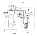
- FIG. 1 illustrates several aspects and embodiments of a low eddy current cryogen circuit 100 of the invention.
- the low eddy current cryogen circuit 100 includes at least one cooling coil 102.
- the cooling coil 102 is made of stainless steel or copper for ease of constructing a leak-tight circuit suitable for operation at cryogenic temperatures.
- any material having a suitable thermal conductivity may be used.
- the cooling coil 102 may fabricated by making a portion of the cooling coil 102 out of a non-electrically conducting material.
- a portion of the cooling coil 102 may be made of a ceramic tube.
- the cooling coil 102 has an input portion 106, an output portion 108 and a semicircular portion 110.
- liquid cryogen is introduced to the cooling coil 102 via the input portion 106 at the bottom of the cooling coil 102.
- a portion of the liquid cryogen vaporizes.
- the cryogen vapor and any remaining liquid cryogen exits the cooling coil 102 via the output portion 108 at the top of the cooling coil 102.
- the semi-circular portion 110 is designed to cool a superconducting magnet of an MRI 300 ( Figure 5 ).
- the semi-circular portion may also be designed to cool superconducting magnets in other applications, such as magnetic separators, motors and generators.
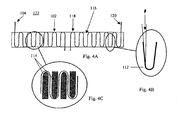
- FIG. 2A illustrates a cooling coil 102 according another embodiment.
- the cooling coil 102 includes a plurality of bends 112 forming a serpentine shape perpendicular to the arc of the semi-circular portion 110.
- the cooling coil 102 of this embodiment provides cooling for a coil of long axial length while keeping thermal conduction paths within the coil itself short, thereby allowing heat to be removed from such a coil without an unacceptable temperature rise at the ends of the coil.
- Figures 4A-4C illustrate additional features and embodiments based on the embodiment illustrated in Figure 2A .
- the bends 112 in the cooling coil 102 are angled such that a gas bubble in a liquid cryogen in the cooling tube 102 would flow upwards under the force of gravity ( Figure 4C ).
- the angle ⁇ of the bends 112 is greater than 0 degrees. However as long as the angle at least 0 degrees, i.e. not negative, the gas bubble will not be trapped in the cooling coil 102. Thus, the cooling coil 102 will not suffer vapor lock.
- filler pieces 114 may be included between the bends 112 in the cooling coil 102.
- the height of the filler pieces is approximately the same as the thickness of the cooling coil 102.
- the filler pieces are made a polymeric material, preferably a phenolic polymer.
- the cooling coil 102 has a diameter less than about 7 mm. More preferably, the cooling coil 102 has a diameter greater than about 3 mm and less than about 7 mm.
- the cooling coil 102 may be first formed into a semicircular shape and affixed to a backing 116, with or without filler pieces 114.
- the cooling coil 102 and the filler pieces may be affixed to a flexible backing 116 and then bent into a semicircular shape.
- the backing 116 with the filler pieces 114 and the cooling coil 102 can then be put in thermal contract with a superconducting coil.
- a cooling band 122 is formed with the addition of a second cooling coil 118 having at least a second electrical isolator 120 incorporated in the second cooling coil 118.
- the second electrical isolator 120 is located to inhibit induced magnetic fields due to inductive coupling of the second cooling coil 118 with eddy current inducing field sources.
- both the first and second cooling coils 102, 118 have substantially semicircular portion 110.
- the first and second cooling coils 102, 118 are located relative to each other to form a cooling band 122 having a substantially circular shape.
- the cooling band 122 can be wrapped around a superconducting coil 302 to provide cooling around the entire circumference of the superconducting coil 302 ( Figure 3A ). Further, if the superconducting coil has a long axial length, a plurality of cooling bands 122 can be provided. If a plurality of cooling bands 122 is provided, manifolds 123 ( Figure 1 ), may also be provided to distribute cryogen among the plurality of cooling bands 122.
- At least some of the plurality of cooling bands 122 are incorporated within windings of the superconducting coil 302.
- This embodiment may be used with thick superconducting coils 302 which may otherwise suffer hot spots within the superconducting coil 302. Further, this embodiment may be combined with the last embodiment. That is, a plurality of cooling bands 122 may be incorporated both within the windings of the superconducting coil 302 and axially along the super conducting coil 302.
- the low eddy current cryogen circuit 100 includes a liquid cryogen reservoir 124 fluidly connected to the first and second cooling coils 102, 118 of the cooling band 122 ( Figure 1 ).
- the liquid cryogen reservoir 124 is located above the first and second cooling coils 102, 118 and is fluidly connected to an input portion 106 located at the bottom of the first and second cooling coils 102, 118. With this arrangement, liquid cryogen flows upward through the cooling band 122. This configuration assists the flow of any vapor formed by evaporation of liquid cryogen through the cooling band 122 and inhibits the formation of a vapor lock in the cooling band 122.
- the low eddy current cryogen circuit 100 includes at least one thermal shield 128.
- the thermal shield 128 intercepts radiation from the ambient atmosphere to the superconducting magnet of a superconducting magnetic device, for example an MRI.
- the thermal shield 128 includes least one thermal shield cooling coil 130 circumscribing the thermal shield 128. Cryogen is introduced to the thermal shield cooling coil 130 via an input portion 131A at one temperature and removed via an output portion 131B at a higher temperature after removing heat from the thermal shield 128.
- the thermal shield cooling coil 130 includes at least one electrical isolator 132 inhibit induced magnetic fields due to inductive coupling of the thermal shield cooling coil 130 with eddy current inducing field sources.
- the thermal shield 128 may be circumscribed by a plurality of thermal shield cooling coils 130. If a plurality of thermal shield cooling coils 130 is provided, manifolds 123, may also be provided to distribute cryogen among the plurality of thermal shield cooling coils 130.
- the low eddy current cryogen circuit 100 includes a cryocooler 134 and a condenser 136 thermally connected to the cryocooler 134. More preferably, the output portion 108 at the top of the cooling coils 102, 118 are fluidly connected to the condenser 136. In this embodiment, vaporized cryogen may be directed to the condenser 136, liquefied, and then sent to the liquid cryogen reservoir 124 to be reused.
- the cryocooler 134 has two stages 135A, 135B.
- the condenser 136 is thermally connected to the second stage 135B of the crycooler 134 while the thermal shield cooling coil 130 is thermally connected to the first stage 135A of the crycooler 134.
- the low eddy current cryogen circuit 100 may be described as comprising two subcircuits, a coil cooling subcircuit 200 and a thermal shield subcircuit 202.
- the coil cooling subcircuit 200 includes the liquid cryogen reservoir 124, the cooling bands 122 and the condenser 136.
- the thermal shield subcircuit 202 includes the thermal shield cooling coil 130 the first stage 135A of the cryocooler 134.
- the coil cooling subcircuit 200 and the thermal shield subcircuit 202 may be connected with a first pressure relief valve 138. If the pressure in the coil cooling subcircuit 200 exceeds a pre-set pressure, cryogen vapor from the coil cooling subcircuit 200 can be released into the thermal shield subcircuit 202. In this manner, the pre-set pressure balances the cooling capacity of the second stage 135B of the cryocooler with the heat load of the from the cooling bands 122.
- a second pressure relief valve 140 may be included to vent the thermal shield subcircuit 202 to the atmosphere.
- cryogen vapor in the thermal shield subcircuit 202 can be released to the atmosphere to reduce the pressure in the thermal shield subcircuit 202 and hence, reduce the pressure in the low eddy current cryogen circuit 100.
- the pressure in the low eddy current cryogen circuit 100 is always above atmospheric pressure during operation. In this manner, atmospheric pressure will not inhibit operation of the low eddy current cryogen circuit 100 due to ingress of air from outside the low eddy current cryogen circuit 100.
- a one-way valve 142 may be included between the first stage 135A of the cryocooler and the infeed portion 131A of the thermal shield cooling coil.
- the one-way valve 142 provides added control over the vapor pressure in the thermal shield subcircuit 202. That is, the one-way valve ensures that cold cryogen flows down to the thermal shield cooling coil 130 and removes heat from the thermal shield 128 during the cool-down procedure and during failure of cooling system due to a power failure or a mechanical failure in the cooling system.
- a heater 126 is located inside the cryogen reservoir 124.
- the heater 126 is turned on whenever the pressure in the cryogen reservoir 124 drops below a pre-set pressure. In this manner, the cooling capacity of the cryocooler 134 can be balanced with the heat load from the cooling bands 122.
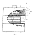
- FIG. 5 illustrates an MRI system 300 comprising a low eddy current cryogen circuit 100.
- the MRI system 300 includes several superconducting magnets 302, a thermal shield 128, gradient coils 306, an RF coil 308, and an RF shield 310 within a housing 312.
- the housing 312 includes a central bore 304 for the patient.
- cooling bands 122 are located on an outer surface of the coil of superconducting magnets 302.
- thermal shield coils 130 are located on an outer surface of the two thermal shields 128.
- the cooling bands 122 may include cooling coils 102, 118 having simple semi-circular shapes as illustrated in Figure 2B or having serpentine bends 112 as illustrated in Figure 2A .
- the present MRI system 300 does not require an internal cryogen vessel.
- the liquid cryogen reservoir 124 may be located outside of the housing 312 and be connected via pipes or tubing (not shown).
- the latent heat of the cryogen in the liquid cryogen reservoir 124 is available to provide "ride-through" (the period of time from the failure of the cooling mechanism to the loss of superconductivity due to a rise in temperature above the critical temperature of the superconducting material).
- ride-through the period of time from the failure of the cooling mechanism to the loss of superconductivity due to a rise in temperature above the critical temperature of the superconducting material.
- the pressure in the low eddy current cryogen circuit 100 rises and both pressure relief valves 138, 140 open. Cryogen boiling off the cooling bands 122 flows into the thermal shield subcircuit, through the thermal shiled cooling coil 130 and vents to atmosphere.
- cryogen in the liquid cryogen reservoir 124 provides latent cooling for ride-through for at least 4 hours. More preferably, cryogen in the liquid cryogen reservoir 124 provides latent cooling for ride-through for at least 12 hours.
Landscapes
- Physics & Mathematics (AREA)
- Electromagnetism (AREA)
- Condensed Matter Physics & Semiconductors (AREA)
- General Physics & Mathematics (AREA)
- Magnetic Resonance Imaging Apparatus (AREA)
- Containers, Films, And Cooling For Superconductive Devices (AREA)
Applications Claiming Priority (2)
| Application Number | Priority Date | Filing Date | Title |
|---|---|---|---|
| US718439 | 2003-11-19 | ||
| US10/718,439 US7464558B2 (en) | 2003-11-19 | 2003-11-19 | Low eddy current cryogen circuit for superconducting magnets |
Publications (2)
| Publication Number | Publication Date |
|---|---|
| EP1533625A1 EP1533625A1 (en) | 2005-05-25 |
| EP1533625B1 true EP1533625B1 (en) | 2009-02-11 |
Family
ID=34435783
Family Applications (1)
| Application Number | Title | Priority Date | Filing Date |
|---|---|---|---|
| EP04257135A Expired - Lifetime EP1533625B1 (en) | 2003-11-19 | 2004-11-17 | Low eddy current cryogen circuit for superconducting magnets |
Country Status (5)
| Country | Link |
|---|---|
| US (2) | US7464558B2 (enExample) |
| EP (1) | EP1533625B1 (enExample) |
| JP (1) | JP4691350B2 (enExample) |
| CN (1) | CN1619720B (enExample) |
| DE (1) | DE602004019374D1 (enExample) |
Families Citing this family (25)
| Publication number | Priority date | Publication date | Assignee | Title |
|---|---|---|---|---|
| FR2887524A1 (fr) * | 2005-06-23 | 2006-12-29 | 1 4 Vin Sarl | Moyen d'inertage a faible vitesse et dispositif mettant en oeuvre ce moyen d'inertage pour conditionner un produit alimentaire |
| US7053740B1 (en) * | 2005-07-15 | 2006-05-30 | General Electric Company | Low field loss cold mass structure for superconducting magnets |
| US7319329B2 (en) | 2005-11-28 | 2008-01-15 | General Electric Company | Cold mass with discrete path substantially conductive coupler for superconducting magnet and cryogenic cooling circuit |
| US7626477B2 (en) * | 2005-11-28 | 2009-12-01 | General Electric Company | Cold mass cryogenic cooling circuit inlet path avoidance of direct conductive thermal engagement with substantially conductive coupler for superconducting magnet |
| US7368913B2 (en) * | 2006-06-30 | 2008-05-06 | General Electric Company | Apparatus and method of providing forced airflow to a surface of a gradient coil |
| US20080209919A1 (en) * | 2007-03-01 | 2008-09-04 | Philips Medical Systems Mr, Inc. | System including a heat exchanger with different cryogenic fluids therein and method of using the same |
| US7962019B2 (en) * | 2007-11-09 | 2011-06-14 | General Electric Company | System, method and apparatus for controlling drift of a main magnetic field in an MRI system |
| US7868617B2 (en) | 2007-11-15 | 2011-01-11 | General Electric Co. | Cooling system and apparatus for controlling drift of a main magnetic field in an MRI system |
| US8882651B2 (en) * | 2008-10-31 | 2014-11-11 | Nexstim Oy | Magnetic stimulation coils with electrically conducting structures |
| US8188742B2 (en) * | 2009-07-31 | 2012-05-29 | General Electric Company | System and method for thermo-electric cooling of RF coils in an MR imaging system |
| CN102054554B (zh) | 2009-10-30 | 2015-07-08 | 通用电气公司 | 超导磁体的制冷系统和制冷方法 |
| GB2490325B (en) * | 2011-04-21 | 2013-04-10 | Siemens Plc | Combined MRI and radiation therapy equipment |
| US9958519B2 (en) * | 2011-12-22 | 2018-05-01 | General Electric Company | Thermosiphon cooling for a magnet imaging system |
| WO2013175928A1 (ja) * | 2012-05-21 | 2013-11-28 | 株式会社 東芝 | 磁気共鳴イメージング装置及び磁気共鳴イメージング装置用の磁石 |
| CN103454604A (zh) | 2012-05-30 | 2013-12-18 | 西门子(深圳)磁共振有限公司 | 磁共振系统的支架式罐形磁体 |
| US10224799B2 (en) * | 2012-10-08 | 2019-03-05 | General Electric Company | Cooling assembly for electrical machines and methods of assembling the same |
| EP2720351B1 (de) * | 2012-10-12 | 2017-04-26 | Siemens Aktiengesellschaft | Vorrichtung zur Entwärmung eines Bauteils einer elektrischen Maschine mittels mehrerer Kühlschlangen |
| CN104076306B (zh) | 2013-03-29 | 2018-06-05 | 通用电气公司 | 热辐射屏蔽组件以及使用该热辐射屏蔽组件的系统 |
| US9575149B2 (en) * | 2014-12-23 | 2017-02-21 | General Electric Company | System and method for cooling a magnetic resonance imaging device |
| US10451318B2 (en) | 2016-12-16 | 2019-10-22 | General Electric Company | Cryogenic cooling system and method |
| US20190075623A1 (en) * | 2017-09-05 | 2019-03-07 | Hydra Heating Industries, LLC | Arc shaped heating coils |
| CN109224319B (zh) * | 2018-08-07 | 2020-06-23 | 中国原子能科学研究院 | 全超导质子治疗系统 |
| CN113050005B (zh) * | 2019-12-26 | 2024-01-30 | 西门子(深圳)磁共振有限公司 | 梯度线圈冷却部件及梯度线圈 |
| CN118140398A (zh) * | 2021-07-13 | 2024-06-04 | 通用电气可再生能源西班牙有限公司 | 电力发电机和冷却系统 |
| CN120811010A (zh) * | 2025-09-15 | 2025-10-17 | 成都理工大学 | 一种超导飞轮储能系统与磁制冷系统耦合运行的装置 |
Family Cites Families (31)
| Publication number | Priority date | Publication date | Assignee | Title |
|---|---|---|---|---|
| JPS57177509A (en) * | 1981-04-24 | 1982-11-01 | Mitsubishi Electric Corp | Superconducting coil device |
| US4601493A (en) * | 1984-04-13 | 1986-07-22 | General Dynamics, Pomona Division | Electrically-isolating coupler suitable for high pressure cryogenic gas flow |
| JPS6171608A (ja) * | 1984-09-17 | 1986-04-12 | Toshiba Corp | 超電導装置 |
| JPH0727814B2 (ja) * | 1985-02-05 | 1995-03-29 | 株式会社日立製作所 | 強制冷却超電導コイル装置 |
| US4782671A (en) * | 1987-09-28 | 1988-11-08 | General Atomics | Cooling apparatus for MRI magnet system and method of use |
| US5148137A (en) * | 1989-11-20 | 1992-09-15 | Advanced Cryo Magnetics, Inc. | Containment vessel for use with a pulsed magnet system and method of manufacturing same |
| JP2563673B2 (ja) | 1990-11-28 | 1996-12-11 | 株式会社東芝 | 電気機器の冷却構造 |
| JPH0738339B2 (ja) * | 1991-10-18 | 1995-04-26 | 株式会社東芝 | 超電導装置 |
| US5412363A (en) * | 1991-12-20 | 1995-05-02 | Applied Superconetics, Inc. | Open access superconducting MRI magnet |
| JPH05175045A (ja) * | 1991-12-26 | 1993-07-13 | Hitachi Ltd | 超電導磁石 |
| US5349297A (en) * | 1992-03-27 | 1994-09-20 | Picker International Inc. | Combined self shielded gradient coil and shimset |
| US5530355A (en) * | 1993-05-13 | 1996-06-25 | Doty Scientific, Inc. | Solenoidal, octopolar, transverse gradient coils |
| JPH0749622A (ja) | 1993-08-05 | 1995-02-21 | Toray Ind Inc | 電子写真プリンタおよび電子写真プリント方法 |
| JPH0757927A (ja) * | 1993-08-17 | 1995-03-03 | Tokyo Electric Power Co Inc:The | 超電導コイル装置 |
| US5461873A (en) | 1993-09-23 | 1995-10-31 | Apd Cryogenics Inc. | Means and apparatus for convectively cooling a superconducting magnet |
| US5539367A (en) | 1994-05-02 | 1996-07-23 | General Electric Company | Superconducting gradient shields in magnetic resonance imaging magnets |
| JP2706631B2 (ja) * | 1994-06-10 | 1998-01-28 | アプライド スーパーコネティクス,インコーポレイテッド | オープンアクセス磁気共鳴撮像装置 |
| US6154109A (en) * | 1995-02-06 | 2000-11-28 | American Superconductor Corporation | Superconducting inductors |
| JP3563476B2 (ja) | 1995-03-09 | 2004-09-08 | 株式会社東芝 | 超電導磁石 |
| US5696476A (en) * | 1995-07-31 | 1997-12-09 | General Electric Company | Open architecture magnetic resonance imaging superconducting magnet assembly |
| GB9705459D0 (en) * | 1997-03-17 | 1997-05-07 | British Tech Group | A gradient drive system for magnetic resonance imaging |
| DE19722387C2 (de) * | 1997-05-28 | 1999-11-11 | Siemens Ag | Antenne für ein Magnetresonanzgerät |
| US5987896A (en) | 1997-08-15 | 1999-11-23 | Panadea Medical Laboratories | System and method for regulating the flow of a fluid refrigerant to a cooling element |
| JPH11233334A (ja) * | 1998-02-18 | 1999-08-27 | Hitachi Ltd | 伝導冷却式超電導磁石装置 |
| US6029458A (en) * | 1998-05-07 | 2000-02-29 | Eckels; Phillip William | Helium recondensing magnetic resonance imager superconducting shield |
| US6078234A (en) * | 1998-07-09 | 2000-06-20 | General Electric Company | Helium vessel for open architecture magnetic resonance imaging superconducting magnet |
| US6255928B1 (en) * | 1998-11-02 | 2001-07-03 | General Electric Company | Magnet having a shim for a laminated pole piece |
| US6448795B1 (en) * | 1999-02-12 | 2002-09-10 | Alexei Ermakov | Three coil apparatus for inductive measurements of conductance |
| JP2002043117A (ja) * | 2000-07-26 | 2002-02-08 | Sumitomo Heavy Ind Ltd | 伝導冷却式超伝導磁石装置 |
| JP4799757B2 (ja) * | 2001-04-26 | 2011-10-26 | 九州電力株式会社 | 超電導磁石 |
| US20050035764A1 (en) * | 2003-08-14 | 2005-02-17 | Anthony Mantone | Method and apparatus for directly cooling hollow conductor wound transverse gradient coil boards |
-
2003
- 2003-11-19 US US10/718,439 patent/US7464558B2/en active Active
-
2004
- 2004-11-17 DE DE602004019374T patent/DE602004019374D1/de not_active Expired - Lifetime
- 2004-11-17 EP EP04257135A patent/EP1533625B1/en not_active Expired - Lifetime
- 2004-11-18 JP JP2004334183A patent/JP4691350B2/ja not_active Expired - Fee Related
- 2004-11-19 CN CN2004100957673A patent/CN1619720B/zh not_active Expired - Fee Related
-
2008
- 2008-10-07 US US12/246,800 patent/US8033121B2/en not_active Expired - Lifetime
Also Published As
| Publication number | Publication date |
|---|---|
| US20090033450A1 (en) | 2009-02-05 |
| US7464558B2 (en) | 2008-12-16 |
| EP1533625A1 (en) | 2005-05-25 |
| JP4691350B2 (ja) | 2011-06-01 |
| CN1619720B (zh) | 2010-12-08 |
| JP2005217392A (ja) | 2005-08-11 |
| US8033121B2 (en) | 2011-10-11 |
| DE602004019374D1 (de) | 2009-03-26 |
| US20050104701A1 (en) | 2005-05-19 |
| CN1619720A (zh) | 2005-05-25 |
Similar Documents
| Publication | Publication Date | Title |
|---|---|---|
| US8033121B2 (en) | Low eddy current cryogen circuit for superconducting magnets | |
| US6995562B2 (en) | Conduction cooled passively-shielded MRI magnet | |
| US7053740B1 (en) | Low field loss cold mass structure for superconducting magnets | |
| EP2183753B1 (en) | Cooling methods | |
| US7323963B2 (en) | MRI superconductive magnet | |
| CN105590715B (zh) | 超导磁体冷却的设备和方法 | |
| EP0681189B1 (en) | Superconducting gradient coil shields in magnetic resonance imaging magnets | |
| US20080115510A1 (en) | Cryostats including current leads for electronically powered equipment | |
| US20100051307A1 (en) | Cooled Current Leads For Cooled Equipment | |
| EP1522867B1 (en) | Superconducting magnet with increased thermal stability | |
| EP1757951A1 (en) | Thin metal layer vacuum vessels with composite structural support | |
| KR102426500B1 (ko) | 극저온 냉각용 배열체 | |
| CN1601662A (zh) | 带有储热器的无致冷剂高温超导磁体 | |
| US5956957A (en) | Cryostat apparatus | |
| US6323749B1 (en) | MRI with superconducting coil | |
| GB2492638A (en) | Superconducting magnet assembly with baffle | |
| CN1847716B (zh) | 用于低温恒温器的再冷凝检修颈部 | |
| JP6644889B2 (ja) | 磁気共鳴撮像(mri)装置及びmri装置用のクライオスタット | |
| JP2004222494A (ja) | 真空保持方法及び真空保持を伴う超伝導機械 | |
| US20210074457A1 (en) | Thermal buses for cryogenic applications | |
| JPH05121236A (ja) | 超電導電流リード | |
| GB2431982A (en) | Cryostat Heat Influx Reduction |
Legal Events
| Date | Code | Title | Description |
|---|---|---|---|
| PUAI | Public reference made under article 153(3) epc to a published international application that has entered the european phase |
Free format text: ORIGINAL CODE: 0009012 |
|
| AK | Designated contracting states |
Kind code of ref document: A1 Designated state(s): AT BE BG CH CY CZ DE DK EE ES FI FR GB GR HU IE IS IT LI LU MC NL PL PT RO SE SI SK TR |
|
| AX | Request for extension of the european patent |
Extension state: AL HR LT LV MK YU |
|
| 17P | Request for examination filed |
Effective date: 20051125 |
|
| AKX | Designation fees paid |
Designated state(s): DE FR GB |
|
| 17Q | First examination report despatched |
Effective date: 20070522 |
|
| GRAP | Despatch of communication of intention to grant a patent |
Free format text: ORIGINAL CODE: EPIDOSNIGR1 |
|
| RIC1 | Information provided on ipc code assigned before grant |
Ipc: G01R 33/3815 20060101AFI20080703BHEP Ipc: H01F 6/04 20060101ALN20080703BHEP |
|
| GRAS | Grant fee paid |
Free format text: ORIGINAL CODE: EPIDOSNIGR3 |
|
| GRAA | (expected) grant |
Free format text: ORIGINAL CODE: 0009210 |
|
| AK | Designated contracting states |
Kind code of ref document: B1 Designated state(s): DE FR GB |
|
| REG | Reference to a national code |
Ref country code: GB Ref legal event code: FG4D |
|
| REF | Corresponds to: |
Ref document number: 602004019374 Country of ref document: DE Date of ref document: 20090326 Kind code of ref document: P |
|
| PLBE | No opposition filed within time limit |
Free format text: ORIGINAL CODE: 0009261 |
|
| STAA | Information on the status of an ep patent application or granted ep patent |
Free format text: STATUS: NO OPPOSITION FILED WITHIN TIME LIMIT |
|
| 26N | No opposition filed |
Effective date: 20091112 |
|
| PGFP | Annual fee paid to national office [announced via postgrant information from national office to epo] |
Ref country code: DE Payment date: 20121128 Year of fee payment: 9 Ref country code: FR Payment date: 20121206 Year of fee payment: 9 |
|
| PGFP | Annual fee paid to national office [announced via postgrant information from national office to epo] |
Ref country code: GB Payment date: 20121126 Year of fee payment: 9 |
|
| GBPC | Gb: european patent ceased through non-payment of renewal fee |
Effective date: 20131117 |
|
| REG | Reference to a national code |
Ref country code: FR Ref legal event code: ST Effective date: 20140731 |
|
| REG | Reference to a national code |
Ref country code: DE Ref legal event code: R119 Ref document number: 602004019374 Country of ref document: DE Effective date: 20140603 |
|
| PG25 | Lapsed in a contracting state [announced via postgrant information from national office to epo] |
Ref country code: DE Free format text: LAPSE BECAUSE OF NON-PAYMENT OF DUE FEES Effective date: 20140603 |
|
| PG25 | Lapsed in a contracting state [announced via postgrant information from national office to epo] |
Ref country code: GB Free format text: LAPSE BECAUSE OF NON-PAYMENT OF DUE FEES Effective date: 20131117 Ref country code: FR Free format text: LAPSE BECAUSE OF NON-PAYMENT OF DUE FEES Effective date: 20131202 |