EP1533586B1 - Two-fluid heat exchanger having flow management open-celled structures - Google Patents
Two-fluid heat exchanger having flow management open-celled structures Download PDFInfo
- Publication number
- EP1533586B1 EP1533586B1 EP03026915A EP03026915A EP1533586B1 EP 1533586 B1 EP1533586 B1 EP 1533586B1 EP 03026915 A EP03026915 A EP 03026915A EP 03026915 A EP03026915 A EP 03026915A EP 1533586 B1 EP1533586 B1 EP 1533586B1
- Authority
- EP
- European Patent Office
- Prior art keywords
- foam
- heat exchanger
- fluid heat
- exchanger according
- fluid
- Prior art date
- Legal status (The legal status is an assumption and is not a legal conclusion. Google has not performed a legal analysis and makes no representation as to the accuracy of the status listed.)
- Expired - Lifetime
Links
- 239000012530 fluid Substances 0.000 title claims abstract description 63
- 239000006260 foam Substances 0.000 claims abstract description 68
- 238000000034 method Methods 0.000 claims abstract description 21
- 238000004519 manufacturing process Methods 0.000 claims abstract description 15
- 239000011148 porous material Substances 0.000 claims description 28
- 210000003041 ligament Anatomy 0.000 claims description 27
- 239000000463 material Substances 0.000 claims description 18
- 238000009826 distribution Methods 0.000 claims description 7
- 239000003779 heat-resistant material Substances 0.000 claims description 7
- 239000007788 liquid Substances 0.000 claims description 7
- 238000005266 casting Methods 0.000 claims description 6
- 230000002349 favourable effect Effects 0.000 claims description 6
- 239000013528 metallic particle Substances 0.000 claims description 6
- 239000000919 ceramic Substances 0.000 claims description 5
- 238000005245 sintering Methods 0.000 claims description 5
- 230000005514 two-phase flow Effects 0.000 claims description 5
- 229920005830 Polyurethane Foam Polymers 0.000 claims description 4
- 238000010438 heat treatment Methods 0.000 claims description 4
- 229910001338 liquidmetal Inorganic materials 0.000 claims description 4
- 239000002984 plastic foam Substances 0.000 claims description 4
- 239000011496 polyurethane foam Substances 0.000 claims description 4
- 239000011248 coating agent Substances 0.000 claims description 3
- 238000000576 coating method Methods 0.000 claims description 3
- 239000002184 metal Substances 0.000 claims description 3
- 239000002904 solvent Substances 0.000 claims description 3
- OKTJSMMVPCPJKN-UHFFFAOYSA-N Carbon Chemical compound [C] OKTJSMMVPCPJKN-UHFFFAOYSA-N 0.000 claims description 2
- 239000011230 binding agent Substances 0.000 claims description 2
- 229910052799 carbon Inorganic materials 0.000 claims description 2
- 239000002131 composite material Substances 0.000 claims description 2
- 238000002156 mixing Methods 0.000 claims description 2
- 239000006262 metallic foam Substances 0.000 abstract description 10
- 230000008569 process Effects 0.000 description 9
- 238000012546 transfer Methods 0.000 description 9
- 230000008020 evaporation Effects 0.000 description 5
- 238000001704 evaporation Methods 0.000 description 5
- 238000009833 condensation Methods 0.000 description 4
- 230000005494 condensation Effects 0.000 description 4
- 238000013461 design Methods 0.000 description 3
- 238000011161 development Methods 0.000 description 3
- 230000018109 developmental process Effects 0.000 description 3
- 239000000203 mixture Substances 0.000 description 3
- 239000011505 plaster Substances 0.000 description 3
- 150000003839 salts Chemical class 0.000 description 3
- 210000004027 cell Anatomy 0.000 description 2
- 230000004048 modification Effects 0.000 description 2
- 238000012986 modification Methods 0.000 description 2
- 239000003507 refrigerant Substances 0.000 description 2
- 230000006978 adaptation Effects 0.000 description 1
- 230000008901 benefit Effects 0.000 description 1
- 230000006835 compression Effects 0.000 description 1
- 238000007906 compression Methods 0.000 description 1
- 238000004132 cross linking Methods 0.000 description 1
- 238000004090 dissolution Methods 0.000 description 1
- 230000005489 elastic deformation Effects 0.000 description 1
- 230000004907 flux Effects 0.000 description 1
- 210000000497 foam cell Anatomy 0.000 description 1
- 239000003292 glue Substances 0.000 description 1
- 230000002401 inhibitory effect Effects 0.000 description 1
- 239000002923 metal particle Substances 0.000 description 1
- 230000000149 penetrating effect Effects 0.000 description 1
- 230000035699 permeability Effects 0.000 description 1
- 238000012545 processing Methods 0.000 description 1
- 230000009467 reduction Effects 0.000 description 1
- 239000011347 resin Substances 0.000 description 1
- 229920005989 resin Polymers 0.000 description 1
- 238000005507 spraying Methods 0.000 description 1
- 230000000087 stabilizing effect Effects 0.000 description 1
- 238000013519 translation Methods 0.000 description 1
- 239000011800 void material Substances 0.000 description 1
Images


Classifications
-
- F—MECHANICAL ENGINEERING; LIGHTING; HEATING; WEAPONS; BLASTING
- F28—HEAT EXCHANGE IN GENERAL
- F28F—DETAILS OF HEAT-EXCHANGE AND HEAT-TRANSFER APPARATUS, OF GENERAL APPLICATION
- F28F13/00—Arrangements for modifying heat-transfer, e.g. increasing, decreasing
- F28F13/003—Arrangements for modifying heat-transfer, e.g. increasing, decreasing by using permeable mass, perforated or porous materials
-
- B—PERFORMING OPERATIONS; TRANSPORTING
- B22—CASTING; POWDER METALLURGY
- B22C—FOUNDRY MOULDING
- B22C9/00—Moulds or cores; Moulding processes
- B22C9/10—Cores; Manufacture or installation of cores
-
- B—PERFORMING OPERATIONS; TRANSPORTING
- B22—CASTING; POWDER METALLURGY
- B22C—FOUNDRY MOULDING
- B22C9/00—Moulds or cores; Moulding processes
- B22C9/10—Cores; Manufacture or installation of cores
- B22C9/105—Salt cores
-
- B—PERFORMING OPERATIONS; TRANSPORTING
- B22—CASTING; POWDER METALLURGY
- B22C—FOUNDRY MOULDING
- B22C9/00—Moulds or cores; Moulding processes
- B22C9/22—Moulds for peculiarly-shaped castings
- B22C9/24—Moulds for peculiarly-shaped castings for hollow articles
- B22C9/26—Moulds for peculiarly-shaped castings for hollow articles for ribbed tubes; for radiators
-
- B—PERFORMING OPERATIONS; TRANSPORTING
- B22—CASTING; POWDER METALLURGY
- B22D—CASTING OF METALS; CASTING OF OTHER SUBSTANCES BY THE SAME PROCESSES OR DEVICES
- B22D25/00—Special casting characterised by the nature of the product
- B22D25/005—Casting metal foams
Definitions
- the present invention relates to a two-fluid heat exchanger as defined in the preamble of claim 1 and to methods of manufacturing it.
- a heat exchanger is known for instance from JP-01252896.
- Heat exchangers including open-celled metallic foam structures through which a liquid or gas phase can flow are already known. Such structures show a significant potential regarding the heat transfer performance mainly because they provide a high surface area per unit volume for effectively exchanging heat.
- the basic structures of such a kind are isotropic foams with properties being independent from any direction.
- these structures with high heat transfer performance show a flow resistance that is too large.
- DE 101 23 456 A1 has disclosed a heat exchanger consisting of metallic open-celled gradient foam.
- the cells of the disclosed foam are connected in such a way that a fluid can flow through it.
- the volume of the foam cells can vary along the path of the heat flux to be dissipated.
- a gradient and consequently an anisotropy in the thermal conductivity and in the flow resistance are achieved. It is intended to vary the cell volume depending on the temperature difference or the velocity of the heat transport, according to this invention.
- Further heat exchanger components are connected to the foam, whereas the components and the open-celled metallic foam can be cast in one piece.
- DE 39 06 446 A1 has also disclosed a heat exchanger with a heat exchanger body containing channels the media can flow through.
- the inside of said channels are provided with a body made of foam through which the fluids can flow.
- the foam body has a variable pore size in radial direction relative to the channel axis. If the pore size increases in radial direction, then an increased flow of the medium will occur in the outside areas of the radius.
- WO 02/42707 A1 discloses a heat exchanger including gradient metallic foam.
- the heat exchanger comprises flow passages for a first fluid, the outer wall of these passages being in heat-transferring contact with a body made of metallic foam through which a second fluid flows.
- This metal foam has a gradient regarding the volume density of the metal, so that it is possible to achieve a favorable equilibrium between heat transfer and conduction, on the one hand, and flow resistance, on the other hand.
- the general objective of the invention is to improve the performance of open-celled foam structures and to manufacture the same cost-efficiently for various applications.
- the invention includes the technical teaching to specify a three-dimensional, anisotropic, open-celled structure,.
- This invention proposes an open-celled structure which is considered as anisotropic in its entirety and with regard to its spatial extension.
- Conventional anisotropic structures known under the state of the art are gradient foam structures as described above, wherein, for example, the size of the pores and/or the size of the ligaments varies continuously with regard to some of their cross sections.
- the open-celled structures according to this invention distinguish in that the three-dimensional network of ligaments and node points on which the open-celled structure is based is provided with a translation invariance, so that the macroscopic properties will remain constant in any individual direction in space. Macroscopic properties do not refer to single pores, but to volumes consisting of at least 3 pores in each direction in space.
- the arising difference in macroscopic properties with regard to the direction in space results from the anisotropy.
- the structure is considered anisotropic when the largest difference in the pore number, measured in two different linear direction in the same structure, does exceed 20%.
- the structure appears to be homogeneous in any direction in space, for example, homogeneous with regard to the shape, permeability or thermal conductivity.
- the structure has, for example, an appearance which is similar to an isotropic foam which is plastically deformed at least in one direction.
- the pores can take on a substantially lens-like or rod-like shape. In dependence upon the cut position, the open pores appear to be circular or ellipsoidal.
- Fluids are liquid and gaseous media or mixtures thereof.
- a preferred embodiment in this respect is the property of a constant flow resistance when a fluid flows through. Due to the anisotropic structure, the fluid flow may encounter a different flow resistance, however, in view of the respective direction, said flow resistance is constant.
- the open-celled structure can be made of metal, carbon or further ceramics, or composites. Different material combinations also guarantee a sufficient variability with regard to the respective constructive design.
- the porosity being defined as the the ratio of the empty volume over the total volume, ranges between 80 % and 99 %.
- the spatial limitation of the individual pores volume lacks in case of open-celled structures.
- the volume of the pores can be defined by the space limited by ligaments and node points.
- the extent of the pore volumes and their distribution is usually described in the literature by the pore number of the structure, measured in any linear direction of the structure. According to a preferred embodiment of the invention, the number of pores can range between 1 and 100 ppi (pores per inch), measured in any linear direction. It is particularly advantageous to select a pore number between 5 and 60 ppi.
- the geometry of the pores is predetermined by a three-dimensional cross-linking of ligaments and their shape.
- rounded ligaments are formed during manufacturing the structure, meeting each other at the node points.
- the ligaments are partially tapered, whereas the node points are thickened.
- a preferred embodiment of the invention proposes that it is possible to develop the ligaments cross section of said structure substantially in oval or polygonal shape.
- the boundary layer of the fluid flow can be developed either favorable or even inhibiting to the flow, in order to possibly regulate the heat transfer between the ligament materials and the fluid and in particular to promote it.
- the ligaments can either be hollow or full.
- hollow ligaments allow with relatively small material amount for a particular stability of the structure against mechanical stress, as well as for high surface area per unit volume.
- a particularly advantageous and thus preferred modification of the invention provides to arrange additional macroscopic flow channels, partially or entirely penetrating the open-celled structure.
- Additionnal channels are considered to be macroscopic if their volume differs from the pore volume of at least a factor of 5.
- fluids, especially liquid/gas mixtures can be drained off the structure favorably and easily during phase-change processes in heat exchangers. This is very important in case of condensation or evaporation processes.
- Straight flow channels represent the easiest constructive design.
- the flow channels can also extend in meander or zigzag shape, wherein the fluid flow in the open-celled structure will be optimized.
- a further aspect of the invention is a method for manufacturing the two-fluid heat exchanger with the anisotropic, open-celled, metallic foam with full ligaments, comprising the following steps:
- Heat resistant and dissolvable materials such as plaster, salt or ceramics can be used as cast material.
- the dissolution of these materials by appropriate solvents has to be free from any residues.
- Foams with full ligaments provide both a highly structural strength and a particularly high thermal conductivity.
- a further aspect of the invention proposes a method for manufacturing the two-fluid heat exchanger having an anisotropic, open-celled metallic foam, comprising the following steps:
- glue can for example be applied first to the surface.
- Foams with hollow ligaments provide a weight saving and are thus very advantageous.
- a foam compressed in at least one direction is being used as a mold for the method for manufacturing a three-dimensional, anisotropic, open-celled structure.
- Compressed foams can either be deformed permanently or - as an alternative - elastic deformations can also be suitable if an appropriate supporting device is provided during the deformation process to stabilize this deformation.
- Deformations in one direction usually lead to lens-shaped pore structures, whereas deformations in two directions preferably perpendicular to one another lead to rod-shaped and rounded structures.
- a preferred embodiment proposes the use of an anisotropic foam as a mold. This structure possesses already the constant properties in each direction in space according to the invention.
- a further aspect of the invention proposes a method for manufacturing a two-fluid heat exchanger having an anisotropic, open-celled metallic foam, comprising the following steps:
- the space holders can originally have the geometrical shape of the pores generated during the sintering process.
- dissolvable materials such as plaster, salts, ceramics or resins are particularly appropriate as space holder material.
- a further aspect of the invention proposes a method for manufacturing a two-fluid heat exchanger having an isotropic, open-celled, metallic foam, comprising the following steps:
- the space holders are made of a heat resistant material, withstanding the temperatures arising during the pressure cast process. Again, the geometrical shape of the space holders corresponds to the pores generated in the further course of the manufacture. And again, dissolvable materials, such as plaster, salts or ceramics are suitable.
- the foam used can serve different functions. On the one hand, the foam serves, for instance, for improving the heat transfer in the fluid flow. On the other hand, the foam can also be used for reducing the noise arising from the flow in the heat exchanger, e.g. at the air outlet of air/refrigerant heat exchangers. Furthermore, such foams can be used as supporting or stabilizing components in the constructive design.
- the heat exchanger has at least one distribution element suitable for two-phase flows and at least one distribution element is partially or fully filled with a three-dimensional, anisotropic, open-celled structure.
- the structure serves for homogeneously distributing the liquid/gas mixture into the respective channels of the heat exchanger.
- the structure is shaped to provide favorable flow features, in particular of two-phase flows.
- the foam insert is shaped in order to reduce the flow resistance. For condensation processes the forming liquid has to be drained effectively out of the foam insert, whereas for evaporation processes, the forming vapor has to be disengaged rapidly out of the foam insert.
- a further aspect of the invention proposes a heat exchanger, in particular a two-fluid heat exchanger, comprising on at least one fluid side a multi-layered structure of different three-dimensional, open-celled foams, wherein at least one layer is composed of a foam according to the invention.
- Each layer provides another function, for instance, regarding the heat transfer, noise reduction, or stability.
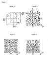
- FIG. 1c Another cross section (B) of the anisotropic foam structure is shown in Figure 1c .
- the anisotropy is clarified in this cross-section, since the structure appears to be compressed in direction [A].
- a compression in this direction affects the cross section (C), as shown in Figure 1d , so that it exhibits the same appearance than cross section (B).
- Figures 2a and b show schematically a cutout of two cross-sections extending perpendicular to one another of a two-fluid heat exchanger according to the invention; the cutout is taken at a location where the heat exchange takes place.
- the illustration shows foam inserts 5 made of anisotropic, open-celled foam structure according to the invention, disposed between separating walls 4.
- flat tubes are utilized as separating walls 4.
- a first fluid 6 and a second fluid 7 flow through the foam structure and the tubes, respectively, so that both fluids run in cross flow, separated one from another.
- the anisotropic, open-celled foam according to the invention is oriented to provide simultaneously a small flow resistance for the first fluid 6 and enough heat exchange surface.
- this type of structure provides enough material at the contact areas between foam structure 5 and separating walls 4, where the heat needs essentially to be dissipated.
- Figure 3a-c illustrates schematically a cutout of a two-fluid heat exchanger, similar to Figure 2 .
- a first fluid 6 and a second fluid 7 flow again through the foam structure and the tubes, respectively, yet so that both fluids run in counterflow, separated one from another.
- the anisotropic open-celled foam is also oriented to simultaneously provide a small flow resistance for the first fluid 6 and enough heat exchange surface.
- macroscopic flow channels 8 are placed in the foam structure. Said channels allow fluids during phase-change processes, such as condensation or evaporation, to drain off the foam structure particularly favorably and easily.
- the flow channels 8 can have different rounded, squared or also stretched cross-sections, as shown in Figure 4b.
- Figure 4c shows examples for the channel run, such as a straight, a meander and a zigzag shape.
- Figure 4a-c shows schematically a cutout of a two-fluid heat exchanger, similar to Figure 2 .
- the anisotropic open celled-foam is again oriented to provide simultaneously a small flow resistance for the first fluid 6 and enough heat exchange surface.
- the foam insert 5 is shaped for favorable flow, in particular for two-phase flows, such as condensation and evaporation.
- the wedge form void part at the exit of the flow channel assists the forming vapor to exit the foam structure quicker, and hence enhances the evaporation process.
Landscapes
- Engineering & Computer Science (AREA)
- Mechanical Engineering (AREA)
- Chemical & Material Sciences (AREA)
- Dispersion Chemistry (AREA)
- Physics & Mathematics (AREA)
- Thermal Sciences (AREA)
- General Engineering & Computer Science (AREA)
- Heat-Exchange Devices With Radiators And Conduit Assemblies (AREA)
- Manufacture Of Porous Articles, And Recovery And Treatment Of Waste Products (AREA)
- Treatment Of Water By Ion Exchange (AREA)
- Filtering Materials (AREA)
Abstract
Description
- The present invention relates to a two-fluid heat exchanger as defined in the preamble of claim 1 and to methods of manufacturing it. Such a heat exchanger is known for instance from JP-01252896.
- Heat exchangers including open-celled metallic foam structures through which a liquid or gas phase can flow are already known. Such structures show a significant potential regarding the heat transfer performance mainly because they provide a high surface area per unit volume for effectively exchanging heat. The basic structures of such a kind are isotropic foams with properties being independent from any direction. However, in a disadvantage manner, these structures with high heat transfer performance show a flow resistance that is too large.
- For this reason, further developments also propose gradient foams.
DE 101 23 456 A1 has disclosed a heat exchanger consisting of metallic open-celled gradient foam. The cells of the disclosed foam are connected in such a way that a fluid can flow through it. The volume of the foam cells can vary along the path of the heat flux to be dissipated. Hence, a gradient and consequently an anisotropy in the thermal conductivity and in the flow resistance are achieved. It is intended to vary the cell volume depending on the temperature difference or the velocity of the heat transport, according to this invention. Further heat exchanger components are connected to the foam, whereas the components and the open-celled metallic foam can be cast in one piece. -
DE 39 06 446 A1 has also disclosed a heat exchanger with a heat exchanger body containing channels the media can flow through. The inside of said channels are provided with a body made of foam through which the fluids can flow. The foam body has a variable pore size in radial direction relative to the channel axis. If the pore size increases in radial direction, then an increased flow of the medium will occur in the outside areas of the radius. - In addition,
WO 02/42707 A1 - Nevertheless, a disadvantage of gradient and isotropic foams remains in the comparatively large flow resistance obtained with the heat transfer performance.
- The general objective of the invention is to improve the performance of open-celled foam structures and to manufacture the same cost-efficiently for various applications.
- The invention is described regarding the two-fluid heat exchanger by the characteristics of claim 1, and regarding the method of manufacturing by the characteristics of claims 13-17. The further claims mentioned thereunder specify advantageous embodiments and further developments of the invention.
- The invention includes the technical teaching to specify a three-dimensional, anisotropic, open-celled structure,.
- This invention proposes an open-celled structure which is considered as anisotropic in its entirety and with regard to its spatial extension. Conventional anisotropic structures known under the state of the art are gradient foam structures as described above, wherein, for example, the size of the pores and/or the size of the ligaments varies continuously with regard to some of their cross sections. For this purpose, the open-celled structures according to this invention distinguish in that the three-dimensional network of ligaments and node points on which the open-celled structure is based is provided with a translation invariance, so that the macroscopic properties will remain constant in any individual direction in space. Macroscopic properties do not refer to single pores, but to volumes consisting of at least 3 pores in each direction in space. The arising difference in macroscopic properties with regard to the direction in space results from the anisotropy. In this invention the structure is considered anisotropic when the largest difference in the pore number, measured in two different linear direction in the same structure, does exceed 20%. In other words: The structure appears to be homogeneous in any direction in space, for example, homogeneous with regard to the shape, permeability or thermal conductivity. The structure has, for example, an appearance which is similar to an isotropic foam which is plastically deformed at least in one direction. As a result, the pores can take on a substantially lens-like or rod-like shape. In dependence upon the cut position, the open pores appear to be circular or ellipsoidal.
- One particular advantage of such structures resides in the high thermal performance obtained with a small flow resistance. Boundary conditions such as the geometry, weight, flow resistance, and heat transfer are frequently defined depending on the application. Because of the variable foam geometry described in the present invention, it is possible to realize an easy and cost-effective adaptation to the mentioned criteria. This adaptability is for instance very important on the air side for air/refrigerant heat exchangers.
- It is of particular interest for numerous applications to adjust said structures to the fluid flow. This is of particular interest in heat exchangers, because the heat transfer performance is directly linked to the fluid flow. Fluids are liquid and gaseous media or mixtures thereof. A preferred embodiment in this respect is the property of a constant flow resistance when a fluid flows through. Due to the anisotropic structure, the fluid flow may encounter a different flow resistance, however, in view of the respective direction, said flow resistance is constant.
- In general, a large number of materials can be considered to be suitable for open-celled structures. They can be selected for each specific application, whereby particularly the easy and cost-effective processing properties of the material should be considered. A particularly advantageous and thus preferred embodiment of the invention proposes that the open-celled structure can be made of metal, carbon or further ceramics, or composites. Different material combinations also guarantee a sufficient variability with regard to the respective constructive design.
- Both, the entire volume of the pores as well as the distribution of pores play a significant role for the flow resistance encountered by flowing fluids. In an advantageous manner, the porosity, being defined as the the ratio of the empty volume over the total volume, ranges between 80 % and 99 %. The spatial limitation of the individual pores volume lacks in case of open-celled structures. However, the volume of the pores can be defined by the space limited by ligaments and node points. The extent of the pore volumes and their distribution is usually described in the literature by the pore number of the structure, measured in any linear direction of the structure. According to a preferred embodiment of the invention, the number of pores can range between 1 and 100 ppi (pores per inch), measured in any linear direction. It is particularly advantageous to select a pore number between 5 and 60 ppi.
- In case of open-celled structures, the geometry of the pores is predetermined by a three-dimensional cross-linking of ligaments and their shape. Normally, rounded ligaments are formed during manufacturing the structure, meeting each other at the node points. The ligaments are partially tapered, whereas the node points are thickened. A preferred embodiment of the invention proposes that it is possible to develop the ligaments cross section of said structure substantially in oval or polygonal shape. Through this embodiment, the boundary layer of the fluid flow can be developed either favorable or even inhibiting to the flow, in order to possibly regulate the heat transfer between the ligament materials and the fluid and in particular to promote it.
- In a preferred manner, the ligaments can either be hollow or full. In fact hollow ligaments allow with relatively small material amount for a particular stability of the structure against mechanical stress, as well as for high surface area per unit volume.
- A particularly advantageous and thus preferred modification of the invention provides to arrange additional macroscopic flow channels, partially or entirely penetrating the open-celled structure. Additionnal channels are considered to be macroscopic if their volume differs from the pore volume of at least a factor of 5. Through this modification, fluids, especially liquid/gas mixtures can be drained off the structure favorably and easily during phase-change processes in heat exchangers. This is very important in case of condensation or evaporation processes.
- Straight flow channels represent the easiest constructive design. In a preferred manner, the flow channels can also extend in meander or zigzag shape, wherein the fluid flow in the open-celled structure will be optimized.
- A further aspect of the invention is a method for manufacturing the two-fluid heat exchanger with the anisotropic, open-celled, metallic foam with full ligaments, comprising the following steps:
- using an open-celled foam, particularly a plastic foam, preferably a polyurethane foam, as a mold,
- casting a material, preferably a heat resistant material in liquid state, into the three-dimensional cavities of the mold and subsequently hardening it,
- removing the mold-forming material by appropriate treatment, particularly by heating or burning; wherein the remaining cast material then represents a negative form with cavities,
- pressure casting liquid metal in the remaining cavities and solidifying it, and,
- removing the negative form.
- Heat resistant and dissolvable materials such as plaster, salt or ceramics can be used as cast material. The dissolution of these materials by appropriate solvents has to be free from any residues. Foams with full ligaments provide both a highly structural strength and a particularly high thermal conductivity.
- As an alternative for foams with hollow ligaments, a further aspect of the invention proposes a method for manufacturing the two-fluid heat exchanger having an anisotropic, open-celled metallic foam, comprising the following steps:
- using an open-celled foam, particularly a plastic foam, preferably a polyurethane foam, as a mold,
- spraying the mold with metallic particles to achieve a full and homogeneous coating of the mold surface,
- sintering the metallic particles, and removing the mold by appropriate treatment, particularly heat treatment.
- To enable a homogeneous coating of the mold with metal particles, glue can for example be applied first to the surface. Foams with hollow ligaments provide a weight saving and are thus very advantageous.
- According to a preferred development of the invention, a foam compressed in at least one direction is being used as a mold for the method for manufacturing a three-dimensional, anisotropic, open-celled structure. Compressed foams can either be deformed permanently or - as an alternative - elastic deformations can also be suitable if an appropriate supporting device is provided during the deformation process to stabilize this deformation. Deformations in one direction usually lead to lens-shaped pore structures, whereas deformations in two directions preferably perpendicular to one another lead to rod-shaped and rounded structures.
- A preferred embodiment proposes the use of an anisotropic foam as a mold. This structure possesses already the constant properties in each direction in space according to the invention.
- As an alternative for foams with full ligaments, a further aspect of the invention proposes a method for manufacturing a two-fluid heat exchanger having an anisotropic, open-celled metallic foam, comprising the following steps:
- mixing and compacting space holders, particularly of heat-resistant material, with metallic particles, solvents and/or binders,
- removing the space holders, and then
- sintering the compacted metallic structure.
- The space holders can originally have the geometrical shape of the pores generated during the sintering process. In this case, dissolvable materials such as plaster, salts, ceramics or resins are particularly appropriate as space holder material.
- As an alternative for foams with full ligaments, a further aspect of the invention proposes a method for manufacturing a two-fluid heat exchanger having an isotropic, open-celled, metallic foam, comprising the following steps:
- compacting space holders, in particular of heat resistant material,
- pressure-casting liquid metal in the remaining cavities, and
- removing the space holders.
- The space holders are made of a heat resistant material, withstanding the temperatures arising during the pressure cast process. Again, the geometrical shape of the space holders corresponds to the pores generated in the further course of the manufacture. And again, dissolvable materials, such as plaster, salts or ceramics are suitable.
- The foam used can serve different functions. On the one hand, the foam serves, for instance, for improving the heat transfer in the fluid flow. On the other hand, the foam can also be used for reducing the noise arising from the flow in the heat exchanger, e.g. at the air outlet of air/refrigerant heat exchangers. Furthermore, such foams can be used as supporting or stabilizing components in the constructive design.
- According to a preferred embodiment, the heat exchanger has at least one distribution element suitable for two-phase flows and at least one distribution element is partially or fully filled with a three-dimensional, anisotropic, open-celled structure. The structure serves for homogeneously distributing the liquid/gas mixture into the respective channels of the heat exchanger.
- In an advantageous manner, the structure is shaped to provide favorable flow features, in particular of two-phase flows. In the use of foam structures according to the invention in two-phase heat exchangers, it means that the foam insert is shaped in order to reduce the flow resistance. For condensation processes the forming liquid has to be drained effectively out of the foam insert, whereas for evaporation processes, the forming vapor has to be disengaged rapidly out of the foam insert.
- A further aspect of the invention proposes a heat exchanger, in particular a two-fluid heat exchanger, comprising on at least one fluid side a multi-layered structure of different three-dimensional, open-celled foams, wherein at least one layer is composed of a foam according to the invention. Each layer provides another function, for instance, regarding the heat transfer, noise reduction, or stability.
- Exemplified embodiments of the invention will be described hereinafter in more detail with reference to the appended drawings, in which:
- Figure 1a
- shows a cubic foam body with three directions in space perpendicular to one another in order to illustrate precisely the following figures;
- Figures 1b-d
- show schematically the cross-section of an anisotropic foam structure, which section is perpendicular to the direction in space [A], [B], and [C], respectively, shown in
Figure 1a ; - Figure 2
- shows schematically a cutout of a two-fluid heat exchanger according to the invention;
- Figure 3
- shows schematically a cutout of a two-fluid heat exchanger according to the invention, with additional macroscopic flow channels;
- Figure 4
- shows schematically a cutout of a two-fluid heat exchanger according to the invention, with foam inserts designed to provide favorable flow features.
- In all figures, the corresponding components are provided with the same reference numbers.
-
Figure 1a shows a cubic body made of a foam structure with three directions in space [A], [B], and [C], perpendicular one to another. The directions in space are perpendicular to the corresponding cross sections (A), (B), and (C). The aim of this figure is to precise the illustrations of the following figures. -
Fig. 1b shows schematically the cross section of an anisotropic foam structure perpendicular to the direction [A]. The illustrated open-celled structure shows pores 1 in different sizes, whose sizes correspond to a statistical distribution. The porosity is defined by theligaments 2 and the conjuncture of ligaments through node points 3. This cross section represents an isotropic structure. - Another cross section (B) of the anisotropic foam structure is shown in
Figure 1c . The anisotropy is clarified in this cross-section, since the structure appears to be compressed in direction [A]. A compression in this direction affects the cross section (C), as shown inFigure 1d , so that it exhibits the same appearance than cross section (B). -
Figures 2a and b show schematically a cutout of two cross-sections extending perpendicular to one another of a two-fluid heat exchanger according to the invention; the cutout is taken at a location where the heat exchange takes place. The illustration shows foam inserts 5 made of anisotropic, open-celled foam structure according to the invention, disposed between separatingwalls 4. In this example, flat tubes are utilized as separatingwalls 4. Afirst fluid 6 and asecond fluid 7 flow through the foam structure and the tubes, respectively, so that both fluids run in cross flow, separated one from another. The anisotropic, open-celled foam according to the invention is oriented to provide simultaneously a small flow resistance for thefirst fluid 6 and enough heat exchange surface. Furthermore, this type of structure provides enough material at the contact areas betweenfoam structure 5 and separatingwalls 4, where the heat needs essentially to be dissipated. -
Figure 3a-c illustrates schematically a cutout of a two-fluid heat exchanger, similar toFigure 2 . Afirst fluid 6 and asecond fluid 7 flow again through the foam structure and the tubes, respectively, yet so that both fluids run in counterflow, separated one from another. The anisotropic open-celled foam is also oriented to simultaneously provide a small flow resistance for thefirst fluid 6 and enough heat exchange surface. In addition,macroscopic flow channels 8 are placed in the foam structure. Said channels allow fluids during phase-change processes, such as condensation or evaporation, to drain off the foam structure particularly favorably and easily. Theflow channels 8 can have different rounded, squared or also stretched cross-sections, as shown inFigure 4b. Figure 4c shows examples for the channel run, such as a straight, a meander and a zigzag shape. -
Figure 4a-c shows schematically a cutout of a two-fluid heat exchanger, similar toFigure 2 . The anisotropic open celled-foam is again oriented to provide simultaneously a small flow resistance for thefirst fluid 6 and enough heat exchange surface. In addition, thefoam insert 5 is shaped for favorable flow, in particular for two-phase flows, such as condensation and evaporation. As an example, the wedge form void part at the exit of the flow channel (seeFigure 4c ) assists the forming vapor to exit the foam structure quicker, and hence enhances the evaporation process. -
- 1
- pores
- 2
- ligaments
- 3
- node points
- 4
- separating wall
- 5
- foam insert
- 6
- first fluid
- 7
- second fluid
- 8
- macroscopic flow channels
- [A], [B], [C]
- direction in space
- (A), (B), (C)
- cross-section
Claims (17)
- A two-fluid heat exchanger, comprising flow passages for a first fluid and flow passages for a second fluid disposed between separating walls, wherein at least one fluid side is provided with a threedimensional, open-celled foam, characterized in that the foam is anisotropic and consists of a three-dimensional network of ligaments and node points forming lens-like or rod-like shaped pores.
- A two-fluid heat exchanger according to claim 1, characterized in that said heat exchanger comprises a multi-layered structure of different three-dimensional, open-celled foams on at least one fluid side, wherein at least one layer is composed of an anisotropic foam consisting of a three-dimensional network of ligaments and node points forming lens-like or rod-like shaped pores.
- A two-fluid heat exchanger according to claims 1 or 2, characterized in that said foam is made of metal, carbon or other ceramic, or composites.
- A two-fluid heat exchanger according to any one of the claims 1 to 3, characterized in that the porosity of said foam is between 80 and 99 %.
- A two-fluid heat exchanger according to any one of the claims 1 to 4, characterized in that the pore number of said foam, measured in any linear direction, ranges between 1 and 100 ppi.
- A two-fluid heat exchanger according to claim 5, characterized in that the pore number of said foam ranges between 5 and 60 ppi.
- A two-fluid heat exchanger according to any one of the claims 1 to 6, characterized in that the ligaments cross sections of said foam are substantially in oval or polygonal shape.
- A two-fluid heat exchanger according to any one of the claims 1 to 7, characterized in that the ligaments of said foam are hollow or full.
- A two-fluid heat exchanger according to any one of the claims 1 to 8, characterized in that said foam comprises additional macroscopic flow channels.
- A two-fluid heat exchanger according to claim 9, characterized in that said flow channels run in meander or zigzag fashion.
- A two-fluid heat exchanger according to any one of the claims 1 to 10, characterized in that said heat exchanger comprises at least one distribution element for two-phase flows and that at least one distribution element is partially or fully filled with a three-dimensional, anisotropic, open-celled foam.
- A two-fluid heat exchanger according to any one of the claims 1 to 11, characterized in that said foam is shaped to provide favorable flow features, in particular for two-phase flows.
- A method for manufacturing a two-fluid heat exchanger according to any one of the claims 1 to 12, having full ligaments, comprising the following steps:- using an anisotropic open-celled foam, in particular a plastic foam, preferably a polyurethane foam, as a mold,- casting a material, preferably a heat-resistant material in liquid state, into the three-dimensional cavities of the mold and subsequently hardening it,- removing the mold-forming material by way of appropriate treatment, particularly by heating or burning; wherein the remaining cast material then constitutes a negative form with cavities,- pressure casting the liquid metal in the remaining cavities and solidifying it, and,- removing the negative form.
- A method for manufacturing a two-fluid heat exchanger according to any one of the claims 1 to 12, having hollow ligaments, comprising the following steps:- using an anisotropic open-celled foam, in particular a plastic foam, preferably a polyurethane foam, as a mold,- layering the mold with metallic particles to achieve a full and homogeneous coating of the entire mold surface,- sintering the metallic particles, and removing the mold by way of appropriate treatment, particularly heat treatment.
- A method according to claim 13 or 14, characterized in that the foam used for said mold is compressed in at least one direction.
- A method for manufacturing a two-fluid heat exchanger according to any one of the claims 1 to 12, having full ligaments, comprising the following steps:- mixing and compacting lens-like or rod-like shaped space holders, particularly of heat resistant material, with metallic particles, solvents and/or binders,- removing the space holders, and then sintering the compacted metallic structure.
- A method for manufacturing a two-fluid heat exchanger according to any one of the claims 1 to 12, having full ligaments, comprising the following steps:- compacting lens-like or rod-like shaped space holders, in particular of heat resistant material,- pressure casting the liquid metal in the remaining cavities, and removing the space holders.
Priority Applications (4)
| Application Number | Priority Date | Filing Date | Title |
|---|---|---|---|
| EP03026915A EP1533586B1 (en) | 2003-11-24 | 2003-11-24 | Two-fluid heat exchanger having flow management open-celled structures |
| ES03026915T ES2371240T3 (en) | 2003-11-24 | 2003-11-24 | TWO FLUID HEAT EXCHANGER WITH OPEN CELL STRUCTURES FOR THE FLOW GOVERNMENT. |
| AT03026915T ATE520002T1 (en) | 2003-11-24 | 2003-11-24 | DUAL-FLUID HEAT EXCHANGER WITH OPEN-PORED STRUCTURE |
| PCT/EP2004/013298 WO2005054768A1 (en) | 2003-11-24 | 2004-11-24 | Two-fluid heat exchangers and methods for manufacturing a metallic foam for two-fluid heat exchangers |
Applications Claiming Priority (1)
| Application Number | Priority Date | Filing Date | Title |
|---|---|---|---|
| EP03026915A EP1533586B1 (en) | 2003-11-24 | 2003-11-24 | Two-fluid heat exchanger having flow management open-celled structures |
Publications (2)
| Publication Number | Publication Date |
|---|---|
| EP1533586A1 EP1533586A1 (en) | 2005-05-25 |
| EP1533586B1 true EP1533586B1 (en) | 2011-08-10 |
Family
ID=34429428
Family Applications (1)
| Application Number | Title | Priority Date | Filing Date |
|---|---|---|---|
| EP03026915A Expired - Lifetime EP1533586B1 (en) | 2003-11-24 | 2003-11-24 | Two-fluid heat exchanger having flow management open-celled structures |
Country Status (4)
| Country | Link |
|---|---|
| EP (1) | EP1533586B1 (en) |
| AT (1) | ATE520002T1 (en) |
| ES (1) | ES2371240T3 (en) |
| WO (1) | WO2005054768A1 (en) |
Cited By (1)
| Publication number | Priority date | Publication date | Assignee | Title |
|---|---|---|---|---|
| DE102020112004A1 (en) | 2020-05-04 | 2021-11-04 | Iav Gmbh Ingenieurgesellschaft Auto Und Verkehr | Exhaust gas heat exchanger and method for producing such an exhaust gas heat exchanger |
Families Citing this family (12)
| Publication number | Priority date | Publication date | Assignee | Title |
|---|---|---|---|---|
| FR2893329B1 (en) * | 2005-11-14 | 2008-05-16 | Aluminium Pechiney Soc Par Act | ELECTROLYSIS TANK WITH THERMAL EXCHANGER. |
| EP1870657A1 (en) * | 2006-06-24 | 2007-12-26 | Colbond B.V. | Heat exchanger |
| US20090288814A1 (en) * | 2008-05-20 | 2009-11-26 | The Boeing Company. | Mixed Carbon Foam/Metallic Heat Exchanger |
| WO2010112393A1 (en) * | 2009-04-03 | 2010-10-07 | Nv Bekaert Sa | Improved heat exchanger |
| US8875395B2 (en) | 2009-10-29 | 2014-11-04 | Universiteit Gent | Manufacturing heat exchanger from porous medium and conduits |
| KR101809519B1 (en) * | 2011-02-18 | 2017-12-15 | 스미토모덴키고교가부시키가이샤 | Porous aluminum member having three-dimensional reticulated structure, collector and electrode using porous aluminum member, method of manufacturing electrode, non-aqueous electrolyte battery using electrode, and capacitor and lithium-ion capacitor using non-aqueous electrolyte solution |
| FR2992716A1 (en) | 2012-06-29 | 2014-01-03 | Filtrauto | POROUS STRUCTURE FOR FLUID INCORPORATING A CONDUIT |
| US20140044951A1 (en) * | 2012-08-09 | 2014-02-13 | United Technologies Corporation | High strength-to-density nanocellular foam |
| CN103206879A (en) * | 2013-04-15 | 2013-07-17 | 江苏联合热交换系统有限公司 | Graphite-foam material heat exchanger and production method thereof |
| DE102016226233A1 (en) * | 2016-12-27 | 2018-06-28 | Robert Bosch Gmbh | flow plate |
| WO2020168012A1 (en) * | 2019-02-13 | 2020-08-20 | Erg Aerospace Corporation | Open cell foam metal heat exchanger |
| EP3711736A1 (en) * | 2019-03-18 | 2020-09-23 | Ontex BVBA | Absorbent articles having an anisotropic foam acquisition layer |
Family Cites Families (8)
| Publication number | Priority date | Publication date | Assignee | Title |
|---|---|---|---|---|
| GB1283192A (en) * | 1968-11-22 | 1972-07-26 | Dunlop Holdings Ltd | Porous articles |
| FR2429988A1 (en) * | 1978-06-28 | 1980-01-25 | Commissariat Energie Atomique | Heat exchanger of anisotropic porous structure - has tubes submerged in fibres of material of good conductivity all oriented similarly between tubes, maximising heat transfer |
| JPS60294A (en) * | 1983-06-16 | 1985-01-05 | Matsushita Seiko Co Ltd | Heat exchanger utilizing foamed metal |
| EP0471552B1 (en) * | 1990-08-14 | 1997-07-02 | Texas Instruments Incorporated | Heat transfer module for ultra high density and silicon on silicon packaging applications |
| DE4424157C2 (en) * | 1993-07-29 | 1996-08-14 | Fraunhofer Ges Forschung | Process for the production of porous metallic materials with anisotropic thermal and electrical conductivities |
| DE19650613B4 (en) * | 1996-12-06 | 2005-12-29 | Daimlerchrysler Ag | Component with a metal foam core |
| DE29814078U1 (en) * | 1998-08-08 | 1998-11-05 | Baxmann, Frank, 41462 Neuss | Sintered heat sink |
| US6196307B1 (en) * | 1998-06-17 | 2001-03-06 | Intersil Americas Inc. | High performance heat exchanger and method |
-
2003
- 2003-11-24 AT AT03026915T patent/ATE520002T1/en not_active IP Right Cessation
- 2003-11-24 EP EP03026915A patent/EP1533586B1/en not_active Expired - Lifetime
- 2003-11-24 ES ES03026915T patent/ES2371240T3/en not_active Expired - Lifetime
-
2004
- 2004-11-24 WO PCT/EP2004/013298 patent/WO2005054768A1/en not_active Ceased
Cited By (1)
| Publication number | Priority date | Publication date | Assignee | Title |
|---|---|---|---|---|
| DE102020112004A1 (en) | 2020-05-04 | 2021-11-04 | Iav Gmbh Ingenieurgesellschaft Auto Und Verkehr | Exhaust gas heat exchanger and method for producing such an exhaust gas heat exchanger |
Also Published As
| Publication number | Publication date |
|---|---|
| ATE520002T1 (en) | 2011-08-15 |
| ES2371240T3 (en) | 2011-12-28 |
| WO2005054768A1 (en) | 2005-06-16 |
| EP1533586A1 (en) | 2005-05-25 |
Similar Documents
| Publication | Publication Date | Title |
|---|---|---|
| EP1533586B1 (en) | Two-fluid heat exchanger having flow management open-celled structures | |
| JP4314352B2 (en) | Technology for improving the thermal characteristics of molds that are manufactured without using solids | |
| US7360581B2 (en) | Structured thermal transfer article | |
| CA1318911C (en) | Device for heat transfer | |
| US5961930A (en) | Integrated micro-ceramic chemical plant with insertable reaction chambers and micro-filters | |
| CA2702997A1 (en) | Heat management device using inorganic foam | |
| KR100549961B1 (en) | Ceramic filter and filtration method of molten metal using the same | |
| MX2013013665A (en) | Method for manufacturing a metal foam provided with channels and resulting metal foam. | |
| AU2009333674A1 (en) | Sintered diamond heat exchanger apparatus | |
| US5965092A (en) | Integrated micro-ceramic chemical plant with insertable micro-filters | |
| EP0930480A3 (en) | Heat exchanger | |
| US6596168B2 (en) | Filter element and method for the manufacture | |
| US12480690B2 (en) | Regenerator for a magnetic heat exchanger and heat exchanger | |
| EP3465063B1 (en) | Evaporator and/or condenser element with superficially embedded porous particles | |
| RU2219016C2 (en) | Method for making heat exchange apparatus | |
| JP4737074B2 (en) | Adsorber and adsorber manufacturing method | |
| JPS6247617B2 (en) | ||
| JPH0733524B2 (en) | Method for manufacturing heat transfer body | |
| Biffi et al. | Thermo-fluid dynamic modeling of Cu based metallic foams for heat exchanger applications | |
| Szafran | Macroscopic and microscopic aspects of designing porous ceramic materials | |
| JPS6335561B2 (en) | ||
| JPS63299847A (en) | Production of heat exchanger | |
| RU97118881A (en) | RADIATOR | |
| RU2001108819A (en) | METHOD FOR PRODUCING HEAT EXCHANGE DEVICES | |
| JPS6021021B2 (en) | Heat exchanger manufacturing method |
Legal Events
| Date | Code | Title | Description |
|---|---|---|---|
| PUAI | Public reference made under article 153(3) epc to a published international application that has entered the european phase |
Free format text: ORIGINAL CODE: 0009012 |
|
| 17P | Request for examination filed |
Effective date: 20040714 |
|
| AK | Designated contracting states |
Kind code of ref document: A1 Designated state(s): AT BE BG CH CY CZ DE DK EE ES FI FR GB GR HU IE IT LI LU MC NL PT RO SE SI SK TR |
|
| AX | Request for extension of the european patent |
Extension state: AL LT LV MK |
|
| AKX | Designation fees paid |
Designated state(s): AT BE BG CH CY CZ DE DK EE ES FI FR GB GR HU IE IT LI LU MC NL PT RO SE SI SK TR |
|
| 17Q | First examination report despatched |
Effective date: 20090320 |
|
| RTI1 | Title (correction) |
Free format text: TWO-FLUID HEAT EXCHANGER HAVING FLOW MANAGEMENT OPEN-CELLED STRUCTURES |
|
| GRAP | Despatch of communication of intention to grant a patent |
Free format text: ORIGINAL CODE: EPIDOSNIGR1 |
|
| GRAS | Grant fee paid |
Free format text: ORIGINAL CODE: EPIDOSNIGR3 |
|
| GRAA | (expected) grant |
Free format text: ORIGINAL CODE: 0009210 |
|
| AK | Designated contracting states |
Kind code of ref document: B1 Designated state(s): AT BE BG CH CY CZ DE DK EE ES FI FR GB GR HU IE IT LI LU MC NL PT RO SE SI SK TR |
|
| REG | Reference to a national code |
Ref country code: GB Ref legal event code: FG4D |
|
| REG | Reference to a national code |
Ref country code: CH Ref legal event code: EP |
|
| REG | Reference to a national code |
Ref country code: IE Ref legal event code: FG4D |
|
| REG | Reference to a national code |
Ref country code: DE Ref legal event code: R096 Ref document number: 60337952 Country of ref document: DE Effective date: 20111013 |
|
| REG | Reference to a national code |
Ref country code: NL Ref legal event code: VDEP Effective date: 20110810 |
|
| REG | Reference to a national code |
Ref country code: ES Ref legal event code: FG2A Ref document number: 2371240 Country of ref document: ES Kind code of ref document: T3 Effective date: 20111228 |
|
| PG25 | Lapsed in a contracting state [announced via postgrant information from national office to epo] |
Ref country code: SE Free format text: LAPSE BECAUSE OF FAILURE TO SUBMIT A TRANSLATION OF THE DESCRIPTION OR TO PAY THE FEE WITHIN THE PRESCRIBED TIME-LIMIT Effective date: 20110810 Ref country code: NL Free format text: LAPSE BECAUSE OF FAILURE TO SUBMIT A TRANSLATION OF THE DESCRIPTION OR TO PAY THE FEE WITHIN THE PRESCRIBED TIME-LIMIT Effective date: 20110810 Ref country code: PT Free format text: LAPSE BECAUSE OF FAILURE TO SUBMIT A TRANSLATION OF THE DESCRIPTION OR TO PAY THE FEE WITHIN THE PRESCRIBED TIME-LIMIT Effective date: 20111212 Ref country code: FI Free format text: LAPSE BECAUSE OF FAILURE TO SUBMIT A TRANSLATION OF THE DESCRIPTION OR TO PAY THE FEE WITHIN THE PRESCRIBED TIME-LIMIT Effective date: 20110810 |
|
| PGFP | Annual fee paid to national office [announced via postgrant information from national office to epo] |
Ref country code: FR Payment date: 20111109 Year of fee payment: 9 Ref country code: ES Payment date: 20111021 Year of fee payment: 9 |
|
| REG | Reference to a national code |
Ref country code: AT Ref legal event code: MK05 Ref document number: 520002 Country of ref document: AT Kind code of ref document: T Effective date: 20110810 |
|
| PG25 | Lapsed in a contracting state [announced via postgrant information from national office to epo] |
Ref country code: CY Free format text: LAPSE BECAUSE OF FAILURE TO SUBMIT A TRANSLATION OF THE DESCRIPTION OR TO PAY THE FEE WITHIN THE PRESCRIBED TIME-LIMIT Effective date: 20110810 Ref country code: SI Free format text: LAPSE BECAUSE OF FAILURE TO SUBMIT A TRANSLATION OF THE DESCRIPTION OR TO PAY THE FEE WITHIN THE PRESCRIBED TIME-LIMIT Effective date: 20110810 Ref country code: GR Free format text: LAPSE BECAUSE OF FAILURE TO SUBMIT A TRANSLATION OF THE DESCRIPTION OR TO PAY THE FEE WITHIN THE PRESCRIBED TIME-LIMIT Effective date: 20111111 Ref country code: AT Free format text: LAPSE BECAUSE OF FAILURE TO SUBMIT A TRANSLATION OF THE DESCRIPTION OR TO PAY THE FEE WITHIN THE PRESCRIBED TIME-LIMIT Effective date: 20110810 |
|
| PG25 | Lapsed in a contracting state [announced via postgrant information from national office to epo] |
Ref country code: BE Free format text: LAPSE BECAUSE OF FAILURE TO SUBMIT A TRANSLATION OF THE DESCRIPTION OR TO PAY THE FEE WITHIN THE PRESCRIBED TIME-LIMIT Effective date: 20110810 |
|
| PG25 | Lapsed in a contracting state [announced via postgrant information from national office to epo] |
Ref country code: SK Free format text: LAPSE BECAUSE OF FAILURE TO SUBMIT A TRANSLATION OF THE DESCRIPTION OR TO PAY THE FEE WITHIN THE PRESCRIBED TIME-LIMIT Effective date: 20110810 Ref country code: CZ Free format text: LAPSE BECAUSE OF FAILURE TO SUBMIT A TRANSLATION OF THE DESCRIPTION OR TO PAY THE FEE WITHIN THE PRESCRIBED TIME-LIMIT Effective date: 20110810 |
|
| PG25 | Lapsed in a contracting state [announced via postgrant information from national office to epo] |
Ref country code: EE Free format text: LAPSE BECAUSE OF FAILURE TO SUBMIT A TRANSLATION OF THE DESCRIPTION OR TO PAY THE FEE WITHIN THE PRESCRIBED TIME-LIMIT Effective date: 20110810 Ref country code: RO Free format text: LAPSE BECAUSE OF FAILURE TO SUBMIT A TRANSLATION OF THE DESCRIPTION OR TO PAY THE FEE WITHIN THE PRESCRIBED TIME-LIMIT Effective date: 20110810 |
|
| PGFP | Annual fee paid to national office [announced via postgrant information from national office to epo] |
Ref country code: DE Payment date: 20120111 Year of fee payment: 9 |
|
| PLBE | No opposition filed within time limit |
Free format text: ORIGINAL CODE: 0009261 |
|
| STAA | Information on the status of an ep patent application or granted ep patent |
Free format text: STATUS: NO OPPOSITION FILED WITHIN TIME LIMIT |
|
| PG25 | Lapsed in a contracting state [announced via postgrant information from national office to epo] |
Ref country code: DK Free format text: LAPSE BECAUSE OF FAILURE TO SUBMIT A TRANSLATION OF THE DESCRIPTION OR TO PAY THE FEE WITHIN THE PRESCRIBED TIME-LIMIT Effective date: 20110810 Ref country code: MC Free format text: LAPSE BECAUSE OF NON-PAYMENT OF DUE FEES Effective date: 20111130 |
|
| REG | Reference to a national code |
Ref country code: CH Ref legal event code: PL |
|
| 26N | No opposition filed |
Effective date: 20120511 |
|
| PG25 | Lapsed in a contracting state [announced via postgrant information from national office to epo] |
Ref country code: CH Free format text: LAPSE BECAUSE OF NON-PAYMENT OF DUE FEES Effective date: 20111130 Ref country code: LI Free format text: LAPSE BECAUSE OF NON-PAYMENT OF DUE FEES Effective date: 20111130 |
|
| REG | Reference to a national code |
Ref country code: IE Ref legal event code: MM4A |
|
| REG | Reference to a national code |
Ref country code: DE Ref legal event code: R097 Ref document number: 60337952 Country of ref document: DE Effective date: 20120511 |
|
| PG25 | Lapsed in a contracting state [announced via postgrant information from national office to epo] |
Ref country code: IE Free format text: LAPSE BECAUSE OF NON-PAYMENT OF DUE FEES Effective date: 20111124 |
|
| PG25 | Lapsed in a contracting state [announced via postgrant information from national office to epo] |
Ref country code: LU Free format text: LAPSE BECAUSE OF NON-PAYMENT OF DUE FEES Effective date: 20111124 |
|
| PG25 | Lapsed in a contracting state [announced via postgrant information from national office to epo] |
Ref country code: BG Free format text: LAPSE BECAUSE OF FAILURE TO SUBMIT A TRANSLATION OF THE DESCRIPTION OR TO PAY THE FEE WITHIN THE PRESCRIBED TIME-LIMIT Effective date: 20111110 |
|
| GBPC | Gb: european patent ceased through non-payment of renewal fee |
Effective date: 20121124 |
|
| REG | Reference to a national code |
Ref country code: FR Ref legal event code: ST Effective date: 20130731 |
|
| PG25 | Lapsed in a contracting state [announced via postgrant information from national office to epo] |
Ref country code: IT Free format text: LAPSE BECAUSE OF NON-PAYMENT OF DUE FEES Effective date: 20121124 |
|
| REG | Reference to a national code |
Ref country code: DE Ref legal event code: R119 Ref document number: 60337952 Country of ref document: DE Effective date: 20130601 |
|
| PG25 | Lapsed in a contracting state [announced via postgrant information from national office to epo] |
Ref country code: TR Free format text: LAPSE BECAUSE OF FAILURE TO SUBMIT A TRANSLATION OF THE DESCRIPTION OR TO PAY THE FEE WITHIN THE PRESCRIBED TIME-LIMIT Effective date: 20110810 |
|
| PG25 | Lapsed in a contracting state [announced via postgrant information from national office to epo] |
Ref country code: DE Free format text: LAPSE BECAUSE OF NON-PAYMENT OF DUE FEES Effective date: 20130601 Ref country code: HU Free format text: LAPSE BECAUSE OF FAILURE TO SUBMIT A TRANSLATION OF THE DESCRIPTION OR TO PAY THE FEE WITHIN THE PRESCRIBED TIME-LIMIT Effective date: 20110810 |
|
| PG25 | Lapsed in a contracting state [announced via postgrant information from national office to epo] |
Ref country code: FR Free format text: LAPSE BECAUSE OF NON-PAYMENT OF DUE FEES Effective date: 20121130 Ref country code: GB Free format text: LAPSE BECAUSE OF NON-PAYMENT OF DUE FEES Effective date: 20121124 |
|
| REG | Reference to a national code |
Ref country code: ES Ref legal event code: FD2A Effective date: 20140305 |
|
| PG25 | Lapsed in a contracting state [announced via postgrant information from national office to epo] |
Ref country code: ES Free format text: LAPSE BECAUSE OF NON-PAYMENT OF DUE FEES Effective date: 20121125 |