EP1533499A1 - Electronic control system of an internal combustion engine - Google Patents
Electronic control system of an internal combustion engine Download PDFInfo
- Publication number
- EP1533499A1 EP1533499A1 EP04027041A EP04027041A EP1533499A1 EP 1533499 A1 EP1533499 A1 EP 1533499A1 EP 04027041 A EP04027041 A EP 04027041A EP 04027041 A EP04027041 A EP 04027041A EP 1533499 A1 EP1533499 A1 EP 1533499A1
- Authority
- EP
- European Patent Office
- Prior art keywords
- internal combustion
- combustion engine
- temperature
- power
- control system
- Prior art date
- Legal status (The legal status is an assumption and is not a legal conclusion. Google has not performed a legal analysis and makes no representation as to the accuracy of the status listed.)
- Ceased
Links
Images

Classifications
-
- F—MECHANICAL ENGINEERING; LIGHTING; HEATING; WEAPONS; BLASTING
- F02—COMBUSTION ENGINES; HOT-GAS OR COMBUSTION-PRODUCT ENGINE PLANTS
- F02D—CONTROLLING COMBUSTION ENGINES
- F02D41/00—Electrical control of supply of combustible mixture or its constituents
- F02D41/30—Controlling fuel injection
- F02D41/32—Controlling fuel injection of the low pressure type
- F02D41/34—Controlling fuel injection of the low pressure type with means for controlling injection timing or duration
-
- F—MECHANICAL ENGINEERING; LIGHTING; HEATING; WEAPONS; BLASTING
- F02—COMBUSTION ENGINES; HOT-GAS OR COMBUSTION-PRODUCT ENGINE PLANTS
- F02D—CONTROLLING COMBUSTION ENGINES
- F02D2250/00—Engine control related to specific problems or objectives
- F02D2250/18—Control of the engine output torque
-
- F—MECHANICAL ENGINEERING; LIGHTING; HEATING; WEAPONS; BLASTING
- F02—COMBUSTION ENGINES; HOT-GAS OR COMBUSTION-PRODUCT ENGINE PLANTS
- F02D—CONTROLLING COMBUSTION ENGINES
- F02D2250/00—Engine control related to specific problems or objectives
- F02D2250/18—Control of the engine output torque
- F02D2250/26—Control of the engine output torque by applying a torque limit
-
- Y—GENERAL TAGGING OF NEW TECHNOLOGICAL DEVELOPMENTS; GENERAL TAGGING OF CROSS-SECTIONAL TECHNOLOGIES SPANNING OVER SEVERAL SECTIONS OF THE IPC; TECHNICAL SUBJECTS COVERED BY FORMER USPC CROSS-REFERENCE ART COLLECTIONS [XRACs] AND DIGESTS
- Y02—TECHNOLOGIES OR APPLICATIONS FOR MITIGATION OR ADAPTATION AGAINST CLIMATE CHANGE
- Y02T—CLIMATE CHANGE MITIGATION TECHNOLOGIES RELATED TO TRANSPORTATION
- Y02T10/00—Road transport of goods or passengers
- Y02T10/10—Internal combustion engine [ICE] based vehicles
- Y02T10/40—Engine management systems
Definitions
- the invention relates to a method for operating an internal combustion engine with an electronic control system for controlling the Fuel injection, in particular the fuel injection in dependence of operating parameters.
- control and adaptation of the Power depending on the load factor.
- a power control of Internal combustion engine depending on the operating parameters and the Load factor.
- the output from the internal combustion engine Engine torque continuously recorded and individual sectors assigned below a roof curve. These individual sectors are valued differently according to the given moment and determine the level and duration of the shared Maximum power.
- Fig. 4 the charge air temperature in a basic configuration and the ambient pressure measured and based on these values a map is evaluated. Including a roof curve is set a correction factor.
- This correction factor determines in the basic configuration directly the injection quantity (quantity limitation).
- concentration limitation For an extension, for example for a higher one Power release, are temperature limits, for example according to the characteristics of Fig. 3, stored. Based on the measured Coolant temperature, these characteristics are evaluated and a Reduction factor determined in addition to the correction factor according to the basic configuration sets the quantity limit.
Landscapes
- Engineering & Computer Science (AREA)
- Chemical & Material Sciences (AREA)
- Combustion & Propulsion (AREA)
- Mechanical Engineering (AREA)
- General Engineering & Computer Science (AREA)
- Electrical Control Of Air Or Fuel Supplied To Internal-Combustion Engine (AREA)
- Combined Controls Of Internal Combustion Engines (AREA)
Abstract
Description
Die Erfindung betrifft ein Verfahren zum Betreiben einer Brennkraftmaschine mit einem elektronischen Regelsystem zur Steuerung der Kraftstoffeinspritzung, insbesondere der Kraftstoffeinspritzung in Abhängigkeit von Betriebsparametern.The invention relates to a method for operating an internal combustion engine with an electronic control system for controlling the Fuel injection, in particular the fuel injection in dependence of operating parameters.
Eine derartige Brennkraftmaschine ist aus der DE 199 53 767 C2 bekannt. Dabei weist diese Brennkraftmaschine zwei Regelsysteme zur Steuerung der Kraftstoffeinspritzung auf, wobei normalerweise die Leistung der Brennkraftmaschine von dem ersten Regler bestimmt wird. Beim Überschreiten eines max. zulässigen Motormoments am Abrieb erfolgt ein Wechsel in der Dominanz zum zweiten Regler, der das leistungsbestimmende Signal so lange reduziert, bis das max. zulässige Motormoment wieder unterschritten wird. Bei dem vorgegebenen max. Motormoment wird von dem tatsächlich bei Prüfstandsläufen ermittelten max. Motormoment einer Brennkraftmaschine der Baureihe ausgegangen, wobei der Anwendungszweck der Brennkraftmaschine berücksichtigt wird.Such an internal combustion engine is known from DE 199 53 767 C2. In this case, this internal combustion engine to two control systems Control of fuel injection, which is usually the Power of the internal combustion engine determined by the first controller becomes. When exceeding a max. permissible engine torque on Abrasion occurs a change in dominance to the second regulator, the the power-determining signal is reduced until the max. permissible engine torque is fallen below again. At the given Max. Engine torque is actually used in test runs determined max. Motor torque of an internal combustion engine of Series gone, the purpose of the internal combustion engine is taken into account.
Der Erfindung liegt die Aufgabe zugrunde, ein Verfahren zum Betreiben einer Brennkraftmaschine mit einem elektronischen Regelsystem zur Steuerung der Kraftstoffeinspritzung anzugeben, das gegenüber dem Stand der Technik vereinfacht ist.The invention is based on the object, a method for operating an internal combustion engine with an electronic control system to indicate the fuel injection control, the opposite The prior art is simplified.
Diese Aufgabe wird dadurch gelöst, dass die in dem Regelsystem eingestellte max. Leistung der Brennkraftmaschine für normale Betriebsbedingungen und einen mittleren Lastfaktor freigegeben und zertifiziert wird. Während bisher jede Brennkraftmaschine gemäß ihrem Einsatzzweck zertifiziert wurde, ist dies nunmehr nicht mehr nötig, da die Steuerung und Anpassung der Leistung in Abhängigkeit von Betriebsparametern erfolgt. Dieses Verfahren kommt insbesondere bei Brennkraftmaschinen zum Einsatz, bei denen die Brennkraftmaschinen einer Baureihe für sehr unterschiedliche Anwendungen und Einsatzbedingungen eingesetzt werden. Solche Anwendungen und Einsatzbedingungen sind beispielsweise Baumaschinen unterschiedlichster Art, landwirtschaftliche Fahrzeuge wie Traktoren und Mähdrescher, Aggregate wie Pumpaggregate, Stromaggregate oder Notstromaggregate sowie Marineeinsätze und Nutzfahrzeuge. Bei all diesen verschiedenen Einsatzmöglichkeiten wird bisher eine auf den speziellen Anwendungsfall abgestimmte Leistungseinstellung vorgenommen, die dann auch individuell von entsprechenden Prüfinstituten zertifiziert werden muss.This object is achieved in that in the control system set max. Power of the internal combustion engine for normal Operating conditions and a medium load factor released and is certified. While hitherto, each internal combustion engine according to has been certified for its purpose, this is now no longer necessary, since the control and adjustment of the power depending of operating parameters. This process comes in particular used in internal combustion engines, in which the internal combustion engines a series for very different applications and conditions of use. Such applications and conditions of use are, for example, construction machines various types, agricultural vehicles such as tractors and combine harvesters, aggregates such as pumping units, generating sets or emergency generators as well as naval missions and commercial vehicles. In all these different uses is so far one adapted to the specific application power setting made, which then also individually by appropriate test institutes must be certified.
In Weiterbildung der Erfindung erfolgt die Steuerung und Anpassung der Leistung in Abhängigkeit der Betriebsparameter:
- Atmosphärendruck,
- Ladelufttemperatur oder Sauglufttemperatur,
- Umgebungstemperatur,
- Kühlmitteltemperatur,
- Ladeluftdruck und
- Abgastemperatur.
- Atmospheric pressure,
- Charge air temperature or suction air temperature,
- Ambient temperature,
- Coolant temperature,
- Charge air pressure and
- Exhaust gas temperature.
Hier sind für die einzelnen Betriebsparameter Maximalwerte vorgegeben, wobei bei Überschreitung eines vorgegebenen Maximalwertes (oder Unterschreitung eines vorgegebenen Minimalwertes) die Leistung entsprechend der vorgegebenen Kennlinien oder Kennfelder in Abhängigkeit der betroffenen Brennkraftmaschinenparameter reduziert wird. Here maximum values are specified for the individual operating parameters, wherein when exceeding a predetermined maximum value (or below a predetermined minimum value) the Power according to the given characteristic curves or maps reduced depending on the affected engine parameters becomes.
In weiterer Ausgestaltung erfolgt die Steuerung und Anpassung der Leistung in Abhängigkeit des Lastfaktors.In a further embodiment, the control and adaptation of the Power depending on the load factor.
In Weiterbildung der Erfindung erfolgt eine Leistungssteuerung der Brennkraftmaschine in Abhängigkeit der Betriebsparameter und des Lastfaktors. Hierzu wird das von der Brennkraftmaschine abgegebene Motormoment kontinuierlich aufgenommen und einzelnen Sektoren unterhalb einer Dachkurve zugeordnet. Diese einzelnen Sektoren werden entsprechend dem abgegebenen Moment unterschiedlich bewertet und bestimmen das Maß und die Dauer der freigegebenen Maximalleistung.In a further development of the invention, a power control of Internal combustion engine depending on the operating parameters and the Load factor. For this purpose, the output from the internal combustion engine Engine torque continuously recorded and individual sectors assigned below a roof curve. These individual sectors are valued differently according to the given moment and determine the level and duration of the shared Maximum power.
Weitere vorteilhafte Ausgestaltungen der Erfindung sind der Zeichnungsbeschreibung zu entnehmen, in der ein in den Figuren dargestelltes Ausführungsbeispiel der Erfindung näher beschrieben ist.Further advantageous embodiments of the invention are the drawing description to take in the one shown in the figures Embodiment of the invention is described in detail.
Es zeigen die
- Fig. 1
- eine Lastkollektivsteuerung der Brennkraftmaschine,
- Fig. 2
- eine Dachkurvensteuerung der Brennkraftmaschine mit unterschiedlichen Bewertungen,
- Fig. 3
- eine Reduktion der Motorleistung in Abhängigkeit von der Temperatur linear oder in Abhängigkeit einer Funktion und
- Fig. 4
- in Diagrammform die Leistungskorrektur in Abhängigkeit der Betriebsparameter.
- Fig. 1
- a load collective control of the internal combustion engine,
- Fig. 2
- a roof cam control of the internal combustion engine with different ratings,
- Fig. 3
- a reduction of engine power as a function of the temperature linear or as a function of a function and
- Fig. 4
- in diagram form the power correction depending on the operating parameters.
Gemäß dem Diagramm nach Fig. 1 ist die Last über der Zeit aufgetragen.
Ausgehend von einem Lastkollektiv von 100 % wird nach
einer ersten Zeitspanne eine Lastreduzierung auf 100 % - x eingestellt.
Das System bestimmt aufgrund dieser Lastreduzierung 100 % -
x gegebenenfalls noch eine weitere Lastreduzierung 100 % - x - y, die
von dem Betreiber nach einer Zeitspanne t2 angestellt wird, nach
welcher Zeitspanne t3 die Motorsteuerung wieder stufenweise die gesamte
Leistung freigibt. Diese Steuerung erfolgt bewertet anhand der
erzwungenen, gegebenenfalls mehreren, Leistungsreduzierungen.
Zusätzlich oder alternativ erfolgt die Steuerung bewertet anhand von
selbst vorgegebenen, ebenfalls gegebenenfalls mehreren, Leistungsreduzierungen.
In dem Diagramm nach Fig. 2 ist die maximale Drehmomentkurve
über der Drehzahl aufgetragen. Unter dieser max.
Drehmomentkurve werden unterschiedliche Abschnitte 1, 2, 3, n eingeteilt,
die unterschiedlich bewertet werden. Je nach dem, in welchem
Bereich die Brennkraftmaschine längere Zeit betrieben wird,
erfolgt eine Reduzierung der Leistung.According to the diagram of Fig. 1, the load is plotted against time. Based on a load spectrum of 100%, a load reduction is set to 100% - x after a first period of time. On the basis of this load reduction, the system determines 100% -x, possibly even a
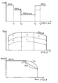
In dem Diagramm gemäß Fig. 3 ist die zu Fig. 4 unter "Erweiterung" dargestellte Reduzierung, ausgehend von 100 %, in Abhängigkeit von verschiedenen Kennlinien dargestellt. a) zeigt eine lineare Reduktion, b1) und b2) zeigen unterschiedliche Reduktionen in Abhängigkeit von unterschiedlichen Funktionen.In the diagram according to FIG. 3, the information relating to FIG. 4 under "extension" is shown. shown reduction, starting from 100%, depending on represented different characteristics. a) shows a linear reduction, b1) and b2) show different reductions depending on different functions.
Gemäß Fig. 4 werden in einer Basiskonfiguration die Ladelufttemperatur und der Umgebungsdruck gemessen und anhand dieser Werte wird ein Kennfeld ausgewertet. Unter Einbezug einer Dachkurve wird damit ein Korrekturfaktor festgelegt. Dieser Korrekturfaktor bestimmt bei der Basiskonfiguration direkt die Einspritzmenge (Mengenbegrenzung). Bei einer Erweiterung, beispielsweise für eine höhere Leistungsfreigabe, sind Temperaturgrenzen, beispielsweise gemäß den Kennlinien nach Fig. 3, abgespeichert. Anhand der gemessenen Kühlmitteltemperatur werden diese Kennlinien ausgewertet und ein Reduktionsfaktor bestimmt, der zusätzlich zu dem Korrekturfaktor gemäß der Basiskonfiguration die Mengenbegrenzung einstellt.According to Fig. 4, the charge air temperature in a basic configuration and the ambient pressure measured and based on these values a map is evaluated. Including a roof curve is set a correction factor. This correction factor determines in the basic configuration directly the injection quantity (quantity limitation). For an extension, for example for a higher one Power release, are temperature limits, for example according to the characteristics of Fig. 3, stored. Based on the measured Coolant temperature, these characteristics are evaluated and a Reduction factor determined in addition to the correction factor according to the basic configuration sets the quantity limit.
Claims (4)
dadurch gekennzeichnet, dass die in dem Regelsystem eingestellte Maximalleistung der Brennkraftmaschine für normale Betriebsbedingungen und einen mittleren Lastfaktor freigegeben und zertifiziert wird.Method for operating an internal combustion engine with an electronic control system for controlling fuel injection, in particular fuel injection as a function of operating parameters,
characterized in that the set in the control system maximum power of the internal combustion engine for normal operating conditions and an average load factor is released and certified.
dadurch gekennzeichnet, dass die Steuerung und Anpassung der Leistung mindestens in Abhängigkeit der Betriebsparameter:
characterized in that the control and adjustment of the power at least depending on the operating parameters:
dadurch gekennzeichnet, dass die Steuerung und Anpassung der Leistung in Abhängigkeit des Lastfaktors erfolgt. Method according to claim 1 or 2,
characterized in that the control and adjustment of the power takes place as a function of the load factor.
dadurch gekennzeichnet, dass eine Freigabe einer zeitlich limitierten Maximalleistung in Abhängigkeit der Betriebsparameter und des Lastfaktors erfolgt.Process according to claims 2 and 3,
characterized in that a release of a time-limited maximum power takes place in dependence of the operating parameters and the load factor.
Applications Claiming Priority (2)
| Application Number | Priority Date | Filing Date | Title |
|---|---|---|---|
| DE10354317A DE10354317A1 (en) | 2003-11-20 | 2003-11-20 | Flexible power control of an internal combustion engine |
| DE10354317 | 2003-11-20 |
Publications (1)
| Publication Number | Publication Date |
|---|---|
| EP1533499A1 true EP1533499A1 (en) | 2005-05-25 |
Family
ID=34428833
Family Applications (1)
| Application Number | Title | Priority Date | Filing Date |
|---|---|---|---|
| EP04027041A Ceased EP1533499A1 (en) | 2003-11-20 | 2004-11-13 | Electronic control system of an internal combustion engine |
Country Status (2)
| Country | Link |
|---|---|
| EP (1) | EP1533499A1 (en) |
| DE (1) | DE10354317A1 (en) |
Cited By (1)
| Publication number | Priority date | Publication date | Assignee | Title |
|---|---|---|---|---|
| FR2982645A1 (en) * | 2011-11-16 | 2013-05-17 | Peugeot Citroen Automobiles Sa | OPERATING CONTROL OF A DIESEL TYPE INTERNAL COMBUSTION ENGINE |
Families Citing this family (1)
| Publication number | Priority date | Publication date | Assignee | Title |
|---|---|---|---|---|
| DE102007013488A1 (en) * | 2007-03-21 | 2008-09-25 | Zf Friedrichshafen Ag | Method for controlling drive train of motor vehicle, involves limiting maximum engine moment continuously in dependence of gearbox temperature |
Citations (5)
| Publication number | Priority date | Publication date | Assignee | Title |
|---|---|---|---|---|
| US5327866A (en) * | 1991-12-24 | 1994-07-12 | Honda Giken Kogyo Kabushiki Kaisha | Ignition timing control system for internal combustion engine |
| US5450829A (en) * | 1994-05-03 | 1995-09-19 | Servojet Products International | Electronically controlled pilot fuel injection of compression ignition engines |
| EP0924416A2 (en) * | 1997-12-15 | 1999-06-23 | Nissan Motor Company, Limited | Control system for diesel engine during cold-engine warm-up period |
| US6032640A (en) * | 1998-10-02 | 2000-03-07 | The University Of British Columbia | Control method for spark-ignition engines |
| US20020157619A1 (en) * | 2001-02-27 | 2002-10-31 | Gray Clint D. J. | Method of operating a dual fuel internal |
Family Cites Families (3)
| Publication number | Priority date | Publication date | Assignee | Title |
|---|---|---|---|---|
| DE4214179C1 (en) * | 1992-04-30 | 1993-05-06 | Mercedes-Benz Aktiengesellschaft, 7000 Stuttgart, De | |
| DE19819122C2 (en) * | 1998-04-29 | 2001-06-28 | Deere & Co | Control device for internal combustion engines |
| DE10203766A1 (en) * | 2002-01-30 | 2003-07-31 | Deutz Ag | Electronic control device for diesel engines, is designed for use with all types of industrial and motor vehicle diesel engines and is able to process and manage a whole range of engine parameters and functions |
-
2003
- 2003-11-20 DE DE10354317A patent/DE10354317A1/en not_active Withdrawn
-
2004
- 2004-11-13 EP EP04027041A patent/EP1533499A1/en not_active Ceased
Patent Citations (5)
| Publication number | Priority date | Publication date | Assignee | Title |
|---|---|---|---|---|
| US5327866A (en) * | 1991-12-24 | 1994-07-12 | Honda Giken Kogyo Kabushiki Kaisha | Ignition timing control system for internal combustion engine |
| US5450829A (en) * | 1994-05-03 | 1995-09-19 | Servojet Products International | Electronically controlled pilot fuel injection of compression ignition engines |
| EP0924416A2 (en) * | 1997-12-15 | 1999-06-23 | Nissan Motor Company, Limited | Control system for diesel engine during cold-engine warm-up period |
| US6032640A (en) * | 1998-10-02 | 2000-03-07 | The University Of British Columbia | Control method for spark-ignition engines |
| US20020157619A1 (en) * | 2001-02-27 | 2002-10-31 | Gray Clint D. J. | Method of operating a dual fuel internal |
Cited By (2)
| Publication number | Priority date | Publication date | Assignee | Title |
|---|---|---|---|---|
| FR2982645A1 (en) * | 2011-11-16 | 2013-05-17 | Peugeot Citroen Automobiles Sa | OPERATING CONTROL OF A DIESEL TYPE INTERNAL COMBUSTION ENGINE |
| WO2013072590A1 (en) * | 2011-11-16 | 2013-05-23 | Peugeot Citroen Automobiles Sa | Controlling the operation of a diesel internal combustion engine |
Also Published As
| Publication number | Publication date |
|---|---|
| DE10354317A1 (en) | 2005-06-23 |
Similar Documents
| Publication | Publication Date | Title |
|---|---|---|
| DE102004006294B3 (en) | Method for equalizing the injection quantity differences between the cylinders of an internal combustion engine | |
| DE102008054690B4 (en) | Method and device for calibrating partial injections in an internal combustion engine, in particular a motor vehicle | |
| EP1716331B1 (en) | Method for synchronizing cylinders in terms of quantities of fuel injection in a heat engine | |
| DE102010017123B4 (en) | Fuel injection control device for internal combustion engines | |
| DE102008040626A1 (en) | Method for determining the injected fuel mass of a single injection and apparatus for carrying out the method | |
| DE3042246A1 (en) | ELECTRONICALLY CONTROLLED FUEL METERING SYSTEM FOR AN INTERNAL COMBUSTION ENGINE | |
| WO1999014488A1 (en) | Method for determining the advance ignition angle in internal combustion engine ignition systems | |
| DE102007053406B3 (en) | Method and device for carrying out both an adaptation and a diagnosis in emission-relevant control devices in a vehicle | |
| EP1254310B1 (en) | System for regulating an internal combustion engine | |
| DE19709395A1 (en) | Knock control method in multi-cylinder internal combustion engines | |
| DE102006004516B3 (en) | Bayes network for controlling and regulating internal combustion engine, has measuring variables that are assigned probabilities, and correction value that is calculated for correcting control variable of controller using correction table | |
| DE19651238C2 (en) | Device determining the ignition angle of an internal combustion engine | |
| DE19706126A1 (en) | Air/fuel ratio regulation method for lean-burn automobile engine | |
| EP1005609B1 (en) | Method for controlling exhaust gas recirculation in an internal combustion engine | |
| DE102016006327A1 (en) | Method and device for adapting an exhaust gas recirculation valve | |
| DE19741565B4 (en) | Method and device for controlling an internal combustion engine | |
| DE112010005933T5 (en) | Control device for an internal combustion engine | |
| EP1178202B1 (en) | Method and apparatus for controlling an internal combustion engine | |
| DE10135077A1 (en) | Method and device for operating a drive motor of a vehicle | |
| EP1533499A1 (en) | Electronic control system of an internal combustion engine | |
| DE10305092B4 (en) | Method for automatic adaptation of a torque model and circuit arrangement | |
| DE102014208941A1 (en) | Method for detecting manipulations made on an injection system of an internal combustion engine, in particular of a motor vehicle | |
| DE102007019641A1 (en) | Method and device for controlling an internal combustion engine | |
| DE10051974A1 (en) | Regulating knock of IC engine with which using adaptable performance graph value for retard setting of ignition angle are prepared and values are assigned operating parameter | |
| DE102005054737A1 (en) | Method for operating an internal combustion engine |
Legal Events
| Date | Code | Title | Description |
|---|---|---|---|
| PUAI | Public reference made under article 153(3) epc to a published international application that has entered the european phase |
Free format text: ORIGINAL CODE: 0009012 |
|
| AK | Designated contracting states |
Kind code of ref document: A1 Designated state(s): AT BE BG CH CY CZ DE DK EE ES FI FR GB GR HU IE IS IT LI LU MC NL PL PT RO SE SI SK TR |
|
| AX | Request for extension of the european patent |
Extension state: AL HR LT LV MK YU |
|
| 17P | Request for examination filed |
Effective date: 20050714 |
|
| AKX | Designation fees paid |
Designated state(s): AT BE BG CH CY CZ DE DK EE ES FI FR GB GR HU IE IS IT LI LU MC NL PL PT RO SE SI SK TR |
|
| STAA | Information on the status of an ep patent application or granted ep patent |
Free format text: STATUS: THE APPLICATION HAS BEEN REFUSED |
|
| 18R | Application refused |
Effective date: 20060414 |