EP1533229B1 - Movable loading system, preferably for loading containers on airplanes - Google Patents
Movable loading system, preferably for loading containers on airplanes Download PDFInfo
- Publication number
- EP1533229B1 EP1533229B1 EP04425850A EP04425850A EP1533229B1 EP 1533229 B1 EP1533229 B1 EP 1533229B1 EP 04425850 A EP04425850 A EP 04425850A EP 04425850 A EP04425850 A EP 04425850A EP 1533229 B1 EP1533229 B1 EP 1533229B1
- Authority
- EP
- European Patent Office
- Prior art keywords
- loading system
- container
- movable loading
- lifting device
- motion
- Prior art date
- Legal status (The legal status is an assumption and is not a legal conclusion. Google has not performed a legal analysis and makes no representation as to the accuracy of the status listed.)
- Not-in-force
Links
- 230000008878 coupling Effects 0.000 claims abstract description 17
- 238000010168 coupling process Methods 0.000 claims abstract description 17
- 238000005859 coupling reaction Methods 0.000 claims abstract description 17
- 230000006641 stabilisation Effects 0.000 claims abstract description 13
- 230000000284 resting effect Effects 0.000 claims abstract description 3
- 230000003019 stabilising effect Effects 0.000 description 5
- 238000000034 method Methods 0.000 description 3
- 238000006073 displacement reaction Methods 0.000 description 2
- 238000012986 modification Methods 0.000 description 1
- 230000004048 modification Effects 0.000 description 1
- 238000005096 rolling process Methods 0.000 description 1
- 125000006850 spacer group Chemical group 0.000 description 1
Images


Classifications
-
- B—PERFORMING OPERATIONS; TRANSPORTING
- B64—AIRCRAFT; AVIATION; COSMONAUTICS
- B64F—GROUND OR AIRCRAFT-CARRIER-DECK INSTALLATIONS SPECIALLY ADAPTED FOR USE IN CONNECTION WITH AIRCRAFT; DESIGNING, MANUFACTURING, ASSEMBLING, CLEANING, MAINTAINING OR REPAIRING AIRCRAFT, NOT OTHERWISE PROVIDED FOR; HANDLING, TRANSPORTING, TESTING OR INSPECTING AIRCRAFT COMPONENTS, NOT OTHERWISE PROVIDED FOR
- B64F1/00—Ground or aircraft-carrier-deck installations
- B64F1/32—Ground or aircraft-carrier-deck installations for handling freight
- B64F1/322—Cargo loaders specially adapted for loading air freight containers or palletized cargo into or out of the aircraft
Definitions
- the present invention relates to a movable loading system, preferably for loading containers on airplanes.
- the invention concerns a movable loading system, studied and realised particularly for loading container within aircraft strive in military airports, but that can be used in any situation when it is necessary carrying out loading and/or unloading operations in inconvenient conditions.
- suitable lifting means are provided.
- systems with hydraulic means are used providing the lifting and introduction of the container within the holds.
- trucks are present providing the hooking of said container, transportation and storing of the same within a hold by hydraulic arms.
- Means provided with cabin and mechanical arms are also present.
- Object of the present invention is therefore that of providing a device allowing all the loading and unloading operations for containers from and on aircrafts, and that can be easily transported.
- Another object of the invention is that of providing on the above device means suitable for it motion.
- a movable loading system preferably for loading containers on aircrafts, characterised in that it comprises at least a lifting device having a resting base and upper sliding means; motion means, provided with removable coupling means; and means for the stabilisation of the position of said container, said position stabilisation means being provided with means for coupling with said container; and in that, during the transportation of said movable loading system, said lifting device and said motion means are coupled each other by said removable coupling means, provided on said motion means, while during the container loading phase, said lifting device and said motion means are separated, and said motion means are coupled by said coupling means to said position stabilisation means; said lifting device being provided under said container, acting as a support, facilitating the introduction of said container within a loading space, lifting and/or making it sliding along said sliding means.
- said sliding means can be comprised of a roll.
- said lifting device can comprise wheels, preferably retractable wheels.
- said lifting device can comprise a jack, provided with an operation lever, and mechanical means.
- said motion means can comprise wheels.
- said motion means can comprise means for controlling the direction, said direction control means being eventually provided with at least a bumper.
- said direction control means can comprise steering axes, provided with a worm screw and at least a screw, to fix the steering angle.
- said steering axes can comprise a motion wrench, suitable to control the steering angle, said wrench comprising a screw coupling and a handle.
- said position stabilisation means can comprise lifting means such as a cylinder - piston device.
- Loading system 1 provides two steering axes 3, the main object of which is that of facilitating manoeuvring during the motion or displacement phases of the loading system 1.
- Said steering axes 3 has a first axis 31, used as a handle for the operator handling the loading system 1, and a second axis 32, on the side of which the wheel 4 pairs are coupled.
- a spacer pair 33 couples axes 31 and 32 at the ends.
- Said steering axes 3 are provided both for moving the loading system 1, and for moving the container to be loaded, as will be more deeply described in the following.
- Screws 34 are provided for the steering operations, coupled with worm screws 35, and a coupling 36 for the motion wrenches 5 of the coupling 36. By rotation of the screws 34, they screw on the worm screw, and, according to the screwing direction, move the axes 31 parallel with respect to the axes 32, thus steering the wheels 4.
- bumpers 37 are present on the front part of the steering wheel 3. By these bumpers 37 it is possible approaching a container to the aircraft hold.
- position stabilising elements 7, comprising a pair of cylinders 71 and of corresponding pistons 72, to a container 6.
- Steering axes 3 are coupled to said position stabilising elements 7, allowing the displacement of the container 6.
- screws 34 are provided to guide said container 6.
- Said steering axes 3 provide suitable fixing means 41 close to the wheels 4, and can be detached from the stabilising elements 7.
- container 6, by stabilising elements 7,mounted on the steering axes 3, is approached to the edge 8 of the aircraft hold, with the relevant door open.
- Approaching is carried out by the wheels 4, and possible misalignment can be corrected by the use of steering axis 3, using the motion wrench 5 to carry out the maneuver.
- the lifting device 2 Once the container 6 is close to the hold edge 8, the lifting device 2. It can be easily completed under visibility and safety conditions. Furthermore, by the retractable wheels 22, positioning is very quick. Once the lifting device 2 is positioned, retractable wheels 22 are retracted, allowing to the base 24 of the lifting device 2 to adhere to the ground. Then, jacks 23 are activated, lifting the arms 25 in such a way to couple the roll 21 to the base of the container 6.
- lifting device 2 Once the lifting device 2 is fixed, making reference to figure 8, one of the steering axes 3 is released, particularly the one closer to the hold edge 8, deactivating the fixing means 41. Thus, pushing the container 6 according to the direction A, the latter enters within the aircraft hold. The container slides on the rear wheels 4 and on the roll 21 of the lifting device 2. In case of difference in height, lifting device 2 can lift the height of the base of the container 6.
- Container 6 is made sliding within the hold, as it is evident from figure 8. Then, also the second steering wheel 3 is separated from the stabilising elements 7. Pistons 72 are introduced again within the cylinders 71, until reaching the configuration of figure 9.
- lifting device 2 is extracted, and container 6 is completely introduced within the hold by standard pulling means.
- loading system 1 is then assembled again.
- it can be used for a new loading operation or it can be fixed within the hold, by fixing hooks, and it can travel along with the goods. In case, it can be used for unloading the goods when the aircraft is arrived.
- the loading system according to the present invention provides all the means for loading and unloading goods or containers, and that it can be assembled in such a way to obtain a versatile device, provided with motion means, that can be transported along with the goods.
- An advantage obtained by the present invention is that said system is a loading and unloading system with a reduced rolling and a reduced pitching of the container.
- a further advantage is that the system can be adapted to each position of the ramp. Thus, it has a great versatility in adapting to the height of the hold or of the loading ramp.
Landscapes
- Engineering & Computer Science (AREA)
- Mechanical Engineering (AREA)
- Aviation & Aerospace Engineering (AREA)
- Handcart (AREA)
- Load-Engaging Elements For Cranes (AREA)
- Ship Loading And Unloading (AREA)
- Loading Or Unloading Of Vehicles (AREA)
Abstract
Description
- The present invention relates to a movable loading system, preferably for loading containers on airplanes.
- More specifically, the invention concerns a movable loading system, studied and realised particularly for loading container within aircraft strive in military airports, but that can be used in any situation when it is necessary carrying out loading and/or unloading operations in inconvenient conditions.
- In the following the specification will be addressed to the application of the device to the loading operation for holds of aircrafts, but it is well evident that it must not be considered limited to this specific use.
- As it is well known, at present, for loading and unloading containers in airports and harbours, suitable lifting means are provided. Particularly, systems with hydraulic means are used providing the lifting and introduction of the container within the holds. For example, trucks are present providing the hooking of said container, transportation and storing of the same within a hold by hydraulic arms. Means provided with cabin and mechanical arms are also present.
- If military airports or inconvenient places are taken into consideration, these kinds of equipments are not present. Thus, difficulties are encountered in these cases for loading and unloading containers from, or in, aircrafts.
- At present, it is possible solving this kind of problems by the transportation of standard loading and unloading equipments within the aircraft hold. This solution has some drawbacks. Above-mentioned equipments reduce the goods that can be loaded within the hold of the aircraft. Furthermore, they are very heavy. Thus they cannot be easily transported or used. Finally, specialised personnel are required for handling the same equipments.
- It is well evident that this procedure is not convenient also under the economical point of view. Further, it cannot be used at all in some circumstances.
- In view of the above, it is well evident the needing of having available a device as that suggested by the present invention, that can be transported along with the goods, and that allows to save space within the holds of the aircrafts.
- Much better would be having available a device providing all the means necessary to the completion of the loading and unloading operations.
- In this context it is included the solution suggested according to the present invention.
- Object of the present invention is therefore that of providing a device allowing all the loading and unloading operations for containers from and on aircrafts, and that can be easily transported.
- Another object of the invention is that of providing on the above device means suitable for it motion.
- Further object of the present invention is that of providing the instruments necessary to the execution of the method and the apparatuses carrying out said method.
- It is therefore specific object of the present invention a movable loading system, preferably for loading containers on aircrafts, characterised in that it comprises at least a lifting device having a resting base and upper sliding means; motion means, provided with removable coupling means; and means for the stabilisation of the position of said container, said position stabilisation means being provided with means for coupling with said container; and in that, during the transportation of said movable loading system, said lifting device and said motion means are coupled each other by said removable coupling means, provided on said motion means, while during the container loading phase, said lifting device and said motion means are separated, and said motion means are coupled by said coupling means to said position stabilisation means; said lifting device being provided under said container, acting as a support, facilitating the introduction of said container within a loading space, lifting and/or making it sliding along said sliding means.
- Always according to the invention, said sliding means can be comprised of a roll.
- Still according to the invention, said lifting device can comprise wheels, preferably retractable wheels.
- Furthermore, according to the invention, said lifting device can comprise a jack, provided with an operation lever, and mechanical means.
- Still according to the invention, said motion means can comprise wheels.
- Always according to the invention, said motion means can comprise means for controlling the direction, said direction control means being eventually provided with at least a bumper.
- Preferably, according to the invention, said direction control means can comprise steering axes, provided with a worm screw and at least a screw, to fix the steering angle.
- Furthermore, according to the invention, said steering axes can comprise a motion wrench, suitable to control the steering angle, said wrench comprising a screw coupling and a handle.
- Still according to the invention, said position stabilisation means can comprise lifting means such as a cylinder - piston device.
- The present invention will be now described, for illustrative but not limitative purposes, according to its preferred embodiments, with particular reference to the figures of the enclosed drawings, wherein:
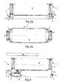
- Figure 1 shows a lateral view of a loading system according to the present invention;
- Figure 2a shows a front view of a lifting device of the loading system of figure 1;
- Figure 2b shows a lateral view of the lifting device of figure 2a;
- Figure 3 shows a top view of a steering axis of the loading system of figure 1;
- Figure 4 shows a wrench with screw coupling for the steering axis of figure 3;
- Figure 5a is a lateral view of the loading system of figure 1, during the first phase of loading a container within an aircraft hold;
- Figure 5b is a top view of the loading system of figure 1, during the first loading phase of a container within a hold of an aircraft;
- Figure 6 is a lateral view of the loading system of figure 1, during the second loading phase of a container within a hold of an aircraft;
- Figure 7 is a lateral view of the loading system of figure 1, during the third loading phase of a container within a hold of an aircraft;
- Figure 8 is a lateral view of the loading system of figure 1, during the fourth loading phase of a container within a hold of an aircraft;
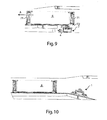
- Figure 9 is a lateral view of the loading system of figure 1, during the fifth loading phase of a container within a hold of an aircraft; and
- Figure 10 is a lateral view of the loading system of figure 1, during the sixth loading phase of a container within a hold of an aircraft.
- Making reference to figure 1, it is possible observing the
loading assembly 1. It provides some means assembled in such a way to make it easily transportable the same system. - Analysing more specifically figures 1, 2, 3 and 4, it is possible to observe the
loading system 1. The various parts of the system can be isolated. Particularly, it is possible to observe thelifting device 2, provided at the top with one ormore rolls 21, and withretractable wheels 22, necessary for its transportation and positioning during the loading phases. Saidlifting device 2 also provides twojacks 23. said jacks 23 are placed on abase plane 24, acting on liftingarms 25. Jacks 23 allow the lifting of therolls 21. Towing hooks 12 are also provided, both frontally and at the rear. -
Loading system 1 provides twosteering axes 3, the main object of which is that of facilitating manoeuvring during the motion or displacement phases of theloading system 1. Saidsteering axes 3 has afirst axis 31, used as a handle for the operator handling theloading system 1, and asecond axis 32, on the side of which thewheel 4 pairs are coupled. A spacer pair 33couples axes - Said
steering axes 3 are provided both for moving theloading system 1, and for moving the container to be loaded, as will be more deeply described in the following.Screws 34 are provided for the steering operations, coupled withworm screws 35, and acoupling 36 for themotion wrenches 5 of thecoupling 36. By rotation of thescrews 34, they screw on the worm screw, and, according to the screwing direction, move theaxes 31 parallel with respect to theaxes 32, thus steering thewheels 4. - Finally,
bumpers 37 are present on the front part of thesteering wheel 3. By thesebumpers 37 it is possible approaching a container to the aircraft hold. - In order to better understand the present invention, operation mode of the preferred embodiment of the loading system will be described, the same mode being valid also for other embodiments.
- In the following, the various phases for loading a container within an aircraft hold will be described.
- Particularly, in figures 5a and 5b it is possible observing the application of
position stabilising elements 7, comprising a pair ofcylinders 71 and ofcorresponding pistons 72, to acontainer 6. Steering axes 3 are coupled to saidposition stabilising elements 7, allowing the displacement of thecontainer 6. screws 34 are provided to guide saidcontainer 6. Saidsteering axes 3 provide suitable fixing means 41 close to thewheels 4, and can be detached from the stabilisingelements 7. - As first loading operation,
container 6, by stabilisingelements 7,mounted on the steering axes 3, is approached to theedge 8 of the aircraft hold, with the relevant door open. Approaching is carried out by thewheels 4, and possible misalignment can be corrected by the use ofsteering axis 3, using themotion wrench 5 to carry out the maneuver. - Once the
container 6 is close to thehold edge 8, thelifting device 2. It can be easily completed under visibility and safety conditions. Furthermore, by theretractable wheels 22, positioning is very quick. Once thelifting device 2 is positioned,retractable wheels 22 are retracted, allowing to thebase 24 of thelifting device 2 to adhere to the ground. Then, jacks 23 are activated, lifting thearms 25 in such a way to couple theroll 21 to the base of thecontainer 6. - Once the
lifting device 2 is fixed, making reference to figure 8, one of the steering axes 3 is released, particularly the one closer to thehold edge 8, deactivating the fixing means 41. Thus, pushing thecontainer 6 according to the direction A, the latter enters within the aircraft hold. The container slides on therear wheels 4 and on theroll 21 of thelifting device 2. In case of difference in height, liftingdevice 2 can lift the height of the base of thecontainer 6. -
Container 6 is made sliding within the hold, as it is evident from figure 8. Then, also thesecond steering wheel 3 is separated from the stabilisingelements 7.Pistons 72 are introduced again within thecylinders 71, until reaching the configuration of figure 9. - As final phase of the loading, lifting
device 2 is extracted, andcontainer 6 is completely introduced within the hold by standard pulling means. - As it can be seen in figure 10,
loading system 1 is then assembled again. Thus, it can be used for a new loading operation or it can be fixed within the hold, by fixing hooks, and it can travel along with the goods. In case, it can be used for unloading the goods when the aircraft is arrived. - On the basis of the previous specification, it can be noted that the basic feature is that the loading system according to the present invention provides all the means for loading and unloading goods or containers, and that it can be assembled in such a way to obtain a versatile device, provided with motion means, that can be transported along with the goods.
- An advantage obtained by the present invention is that said system is a loading and unloading system with a reduced rolling and a reduced pitching of the container.
- A further advantage is that the system can be adapted to each position of the ramp. Thus, it has a great versatility in adapting to the height of the hold or of the loading ramp.
- The present invention has been described for illustrative but not limitative purposes, according to its preferred embodiments, but it is to be understood that modifications and/or changes can be introduced by those skilled in the art without departing from the relevant scope as defined in the enclosed claims.
Claims (16)
- Movable loading system (1), preferably for loading containers on aircrafts, characterised in that it comprises at least a lifting device (2) having a resting base (24) and upper sliding means (21); motion means, provided with removable coupling means (41); and means (7) for the stabilisation of the position of said container (6), said position stabilisation means (7) being provided with means (41) for coupling with said container; and in that, during the transportation of said movable loading system (1), said lifting device (2) and said motion means are coupled each other by said removable coupling means (41), provided on said motion means, while during the container loading phase, said lifting device (2) and said motion means are separated, and said motion means are coupled by said coupling means to said position stabilisation means (7); said lifting device (2) being provided under said container (6), acting as a support, facilitating the introduction of said container (6) within a loading space, lifting and/or making it sliding along said sliding means (21).
- Movable loading system (1) according to claim 1, characterised in that said sliding means (21) comprise a roll.
- Movable loading system (1) according to one of the preceding claims, characterised in that said lifting device (2) comprises wheels (22), preferably retractable wheels.
- Movable loading system (1) according to one of the preceding claims, characterised in that said lifting device (2) comprises a jack (23), provided with an operation lever.
- Movable loading system (1) according to one of the preceding claims, characterised in that said lifting device (2) comprises, mechanical arms (25).
- Movable loading system (1) according to one of the preceding claims, characterised in that said motion means comprise wheels (4).
- Movable loading system (1) according to one of the preceding claims, characterised in that said motion means comprise means (3) or controlling the direction.
- Movable loading system (1) according to claim 7, characterised in that said direction control means comprise at least a bumpen (37).
- Movable loading system (1) according to claim 7 or 8, characterised in that said direction control means comprise steering axes (3).
- Movable loading system (1) according to claim 9, characterised in that said steering axes (3) comprise at least a worm screw (35) and at least a screw (34), to fix the steering angle.
- Movable loading system (1) according to claim 9 or 10, characterised in that said steering axes (3) comprise a motion wrench (5), suitable to control the steering angle.
- Movable loading system (1) according to claim 11, characterised in that said motion wrench (5) comprises a screw coupling (36) and a handle.
- Movable loading system (1) according to one of the preceding claims, characterised in that said stabilisation means (7) are provided directly on said container (6).
- Movable loading system (1) according to one of the preceding claims 1 - 12, characterised in that said stabilisation means (7) are provided separated from said container (6).
- Movable loading system (1) according to one of the preceding claims, characterised in that said position stabilisation means (7) compnse lifting means.
- Movable loading system (1) according to claim 15, characterised in that said lifting device comprises a cylinder - piston device (71, 72).
Applications Claiming Priority (2)
| Application Number | Priority Date | Filing Date | Title |
|---|---|---|---|
| ITRM20030543 | 2003-11-19 | ||
| IT000543A ITRM20030543A1 (en) | 2003-11-19 | 2003-11-19 | MOBILE LOADING COMPLEX, PREFERABLY FOR |
Publications (3)
| Publication Number | Publication Date |
|---|---|
| EP1533229A2 EP1533229A2 (en) | 2005-05-25 |
| EP1533229A3 EP1533229A3 (en) | 2005-11-09 |
| EP1533229B1 true EP1533229B1 (en) | 2006-09-06 |
Family
ID=34430803
Family Applications (1)
| Application Number | Title | Priority Date | Filing Date |
|---|---|---|---|
| EP04425850A Not-in-force EP1533229B1 (en) | 2003-11-19 | 2004-11-15 | Movable loading system, preferably for loading containers on airplanes |
Country Status (4)
| Country | Link |
|---|---|
| EP (1) | EP1533229B1 (en) |
| AT (1) | ATE338683T1 (en) |
| DE (1) | DE602004002258D1 (en) |
| IT (1) | ITRM20030543A1 (en) |
Families Citing this family (2)
| Publication number | Priority date | Publication date | Assignee | Title |
|---|---|---|---|---|
| CN104192320B (en) * | 2014-09-19 | 2016-06-01 | 扬州万方电子技术有限责任公司 | A kind of novel extension bullet car |
| CN106184808B (en) * | 2016-08-25 | 2018-09-25 | 西安睿诺新能源有限公司 | A kind of location regulating system of bomb truck |
Family Cites Families (5)
| Publication number | Priority date | Publication date | Assignee | Title |
|---|---|---|---|---|
| US3972427A (en) * | 1974-09-25 | 1976-08-03 | The Boeing Company | Appendant elevatable loader for vehicles |
| US4312619A (en) * | 1979-07-19 | 1982-01-26 | Fmc Corporation | Aircraft cargo loading method and apparatus |
| US4304518A (en) * | 1980-01-07 | 1981-12-08 | Cochran Airport Systems | Aircraft loader |
| FR2567083A1 (en) * | 1984-07-03 | 1986-01-10 | Bennes Marrel | Loading and transport vehicle for airport |
| DE4040913A1 (en) * | 1990-12-20 | 1992-07-02 | Trepel Hebe Foerdertech | Self-propelled elevating truck for containers, pallets etc. - has vertical hydraulic cylinders at each end of scissors lift to give additional support |
-
2003
- 2003-11-19 IT IT000543A patent/ITRM20030543A1/en unknown
-
2004
- 2004-11-15 DE DE602004002258T patent/DE602004002258D1/en active Active
- 2004-11-15 EP EP04425850A patent/EP1533229B1/en not_active Not-in-force
- 2004-11-15 AT AT04425850T patent/ATE338683T1/en not_active IP Right Cessation
Also Published As
| Publication number | Publication date |
|---|---|
| ITRM20030543A1 (en) | 2004-02-18 |
| ATE338683T1 (en) | 2006-09-15 |
| EP1533229A2 (en) | 2005-05-25 |
| EP1533229A3 (en) | 2005-11-09 |
| DE602004002258D1 (en) | 2006-10-19 |
Similar Documents
| Publication | Publication Date | Title |
|---|---|---|
| EP1610976B1 (en) | Device for loading and unloading a storage container with respect to a transport vehicle and associated system and method | |
| US5800114A (en) | Container handling device | |
| US7100896B1 (en) | Shipping container handling system | |
| US7377398B2 (en) | Portable knockdown trolley hoist | |
| US4997331A (en) | Aircraft ground handling vehicle | |
| US10723605B2 (en) | Forklift adapter | |
| US11603300B2 (en) | Apparatus for handling heavy components on containers | |
| US9254971B1 (en) | Mobile loading dock with wheel assembly | |
| JP2003505313A (en) | Container handling equipment or underframe | |
| EP1533229B1 (en) | Movable loading system, preferably for loading containers on airplanes | |
| MX2013010776A (en) | System and method of loading and unloading containers. | |
| US5236299A (en) | Hitching device for industrial vehicle | |
| US10752147B1 (en) | Lowerable and raisable vehicle trailer system, and method of operating a vehicle trailer system | |
| AU2008101058B4 (en) | A wheel stillage | |
| US10625652B2 (en) | System for accommodating objects | |
| EP4282706A1 (en) | Working equipment with a lift frame assembly | |
| US11897633B2 (en) | System and method for providing maintenance and repair units for maintenance work on aircraft | |
| US20230045842A1 (en) | Container handling apparatus and system for interfacing with a telescoping conveyor | |
| GB2246116A (en) | Lifting and setting-down apparatus for transportable large receptacles | |
| KR20010040404A (en) | Supporting member with alternating positions and its use | |
| GB2047662A (en) | Container handling apparatus |
Legal Events
| Date | Code | Title | Description |
|---|---|---|---|
| PUAI | Public reference made under article 153(3) epc to a published international application that has entered the european phase |
Free format text: ORIGINAL CODE: 0009012 |
|
| AK | Designated contracting states |
Kind code of ref document: A2 Designated state(s): AT BE BG CH CY CZ DE DK EE ES FI FR GB GR HU IE IS IT LI LU MC NL PL PT RO SE SI SK TR |
|
| AX | Request for extension of the european patent |
Extension state: AL HR LT LV MK YU |
|
| PUAL | Search report despatched |
Free format text: ORIGINAL CODE: 0009013 |
|
| AK | Designated contracting states |
Kind code of ref document: A3 Designated state(s): AT BE BG CH CY CZ DE DK EE ES FI FR GB GR HU IE IS IT LI LU MC NL PL PT RO SE SI SK TR |
|
| AX | Request for extension of the european patent |
Extension state: AL HR LT LV MK YU |
|
| 17P | Request for examination filed |
Effective date: 20060306 |
|
| GRAP | Despatch of communication of intention to grant a patent |
Free format text: ORIGINAL CODE: EPIDOSNIGR1 |
|
| AKX | Designation fees paid |
Designated state(s): AT BE BG CH CY CZ DE DK EE ES FI FR GB GR HU IE IS IT LI LU MC NL PL PT RO SE SI SK TR |
|
| GRAS | Grant fee paid |
Free format text: ORIGINAL CODE: EPIDOSNIGR3 |
|
| GRAA | (expected) grant |
Free format text: ORIGINAL CODE: 0009210 |
|
| AK | Designated contracting states |
Kind code of ref document: B1 Designated state(s): AT BE BG CH CY CZ DE DK EE ES FI FR GB GR HU IE IS IT LI LU MC NL PL PT RO SE SI SK TR |
|
| PG25 | Lapsed in a contracting state [announced via postgrant information from national office to epo] |
Ref country code: IT Free format text: LAPSE BECAUSE OF FAILURE TO SUBMIT A TRANSLATION OF THE DESCRIPTION OR TO PAY THE FEE WITHIN THE PRESCRIBED TIME-LIMIT;WARNING: LAPSES OF ITALIAN PATENTS WITH EFFECTIVE DATE BEFORE 2007 MAY HAVE OCCURRED AT ANY TIME BEFORE 2007. THE CORRECT EFFECTIVE DATE MAY BE DIFFERENT FROM THE ONE RECORDED. Effective date: 20060906 Ref country code: CZ Free format text: LAPSE BECAUSE OF FAILURE TO SUBMIT A TRANSLATION OF THE DESCRIPTION OR TO PAY THE FEE WITHIN THE PRESCRIBED TIME-LIMIT Effective date: 20060906 Ref country code: FI Free format text: LAPSE BECAUSE OF FAILURE TO SUBMIT A TRANSLATION OF THE DESCRIPTION OR TO PAY THE FEE WITHIN THE PRESCRIBED TIME-LIMIT Effective date: 20060906 Ref country code: PL Free format text: LAPSE BECAUSE OF FAILURE TO SUBMIT A TRANSLATION OF THE DESCRIPTION OR TO PAY THE FEE WITHIN THE PRESCRIBED TIME-LIMIT Effective date: 20060906 Ref country code: NL Free format text: LAPSE BECAUSE OF FAILURE TO SUBMIT A TRANSLATION OF THE DESCRIPTION OR TO PAY THE FEE WITHIN THE PRESCRIBED TIME-LIMIT Effective date: 20060906 Ref country code: BE Free format text: LAPSE BECAUSE OF FAILURE TO SUBMIT A TRANSLATION OF THE DESCRIPTION OR TO PAY THE FEE WITHIN THE PRESCRIBED TIME-LIMIT Effective date: 20060906 Ref country code: CH Free format text: LAPSE BECAUSE OF FAILURE TO SUBMIT A TRANSLATION OF THE DESCRIPTION OR TO PAY THE FEE WITHIN THE PRESCRIBED TIME-LIMIT Effective date: 20060906 Ref country code: AT Free format text: LAPSE BECAUSE OF FAILURE TO SUBMIT A TRANSLATION OF THE DESCRIPTION OR TO PAY THE FEE WITHIN THE PRESCRIBED TIME-LIMIT Effective date: 20060906 Ref country code: SI Free format text: LAPSE BECAUSE OF FAILURE TO SUBMIT A TRANSLATION OF THE DESCRIPTION OR TO PAY THE FEE WITHIN THE PRESCRIBED TIME-LIMIT Effective date: 20060906 Ref country code: LI Free format text: LAPSE BECAUSE OF FAILURE TO SUBMIT A TRANSLATION OF THE DESCRIPTION OR TO PAY THE FEE WITHIN THE PRESCRIBED TIME-LIMIT Effective date: 20060906 Ref country code: RO Free format text: LAPSE BECAUSE OF FAILURE TO SUBMIT A TRANSLATION OF THE DESCRIPTION OR TO PAY THE FEE WITHIN THE PRESCRIBED TIME-LIMIT Effective date: 20060906 Ref country code: SK Free format text: LAPSE BECAUSE OF FAILURE TO SUBMIT A TRANSLATION OF THE DESCRIPTION OR TO PAY THE FEE WITHIN THE PRESCRIBED TIME-LIMIT Effective date: 20060906 |
|
| REG | Reference to a national code |
Ref country code: GB Ref legal event code: FG4D |
|
| REG | Reference to a national code |
Ref country code: CH Ref legal event code: EP |
|
| REG | Reference to a national code |
Ref country code: IE Ref legal event code: FG4D |
|
| REF | Corresponds to: |
Ref document number: 602004002258 Country of ref document: DE Date of ref document: 20061019 Kind code of ref document: P |
|
| PG25 | Lapsed in a contracting state [announced via postgrant information from national office to epo] |
Ref country code: IE Free format text: LAPSE BECAUSE OF NON-PAYMENT OF DUE FEES Effective date: 20061115 |
|
| PG25 | Lapsed in a contracting state [announced via postgrant information from national office to epo] |
Ref country code: MC Free format text: LAPSE BECAUSE OF NON-PAYMENT OF DUE FEES Effective date: 20061130 |
|
| PG25 | Lapsed in a contracting state [announced via postgrant information from national office to epo] |
Ref country code: SE Free format text: LAPSE BECAUSE OF FAILURE TO SUBMIT A TRANSLATION OF THE DESCRIPTION OR TO PAY THE FEE WITHIN THE PRESCRIBED TIME-LIMIT Effective date: 20061206 Ref country code: BG Free format text: LAPSE BECAUSE OF FAILURE TO SUBMIT A TRANSLATION OF THE DESCRIPTION OR TO PAY THE FEE WITHIN THE PRESCRIBED TIME-LIMIT Effective date: 20061206 Ref country code: DK Free format text: LAPSE BECAUSE OF FAILURE TO SUBMIT A TRANSLATION OF THE DESCRIPTION OR TO PAY THE FEE WITHIN THE PRESCRIBED TIME-LIMIT Effective date: 20061206 |
|
| PG25 | Lapsed in a contracting state [announced via postgrant information from national office to epo] |
Ref country code: DE Free format text: LAPSE BECAUSE OF FAILURE TO SUBMIT A TRANSLATION OF THE DESCRIPTION OR TO PAY THE FEE WITHIN THE PRESCRIBED TIME-LIMIT Effective date: 20061207 |
|
| PG25 | Lapsed in a contracting state [announced via postgrant information from national office to epo] |
Ref country code: ES Free format text: LAPSE BECAUSE OF FAILURE TO SUBMIT A TRANSLATION OF THE DESCRIPTION OR TO PAY THE FEE WITHIN THE PRESCRIBED TIME-LIMIT Effective date: 20061217 |
|
| PG25 | Lapsed in a contracting state [announced via postgrant information from national office to epo] |
Ref country code: IS Free format text: LAPSE BECAUSE OF FAILURE TO SUBMIT A TRANSLATION OF THE DESCRIPTION OR TO PAY THE FEE WITHIN THE PRESCRIBED TIME-LIMIT Effective date: 20070106 |
|
| PG25 | Lapsed in a contracting state [announced via postgrant information from national office to epo] |
Ref country code: PT Free format text: LAPSE BECAUSE OF FAILURE TO SUBMIT A TRANSLATION OF THE DESCRIPTION OR TO PAY THE FEE WITHIN THE PRESCRIBED TIME-LIMIT Effective date: 20070219 |
|
| NLV1 | Nl: lapsed or annulled due to failure to fulfill the requirements of art. 29p and 29m of the patents act | ||
| REG | Reference to a national code |
Ref country code: CH Ref legal event code: PL |
|
| ET | Fr: translation filed | ||
| PLBE | No opposition filed within time limit |
Free format text: ORIGINAL CODE: 0009261 |
|
| STAA | Information on the status of an ep patent application or granted ep patent |
Free format text: STATUS: NO OPPOSITION FILED WITHIN TIME LIMIT |
|
| 26N | No opposition filed |
Effective date: 20070607 |
|
| GRAL | Information related to payment of fee for publishing/printing deleted |
Free format text: ORIGINAL CODE: EPIDOSDIGR3 |
|
| PG25 | Lapsed in a contracting state [announced via postgrant information from national office to epo] |
Ref country code: GR Free format text: LAPSE BECAUSE OF FAILURE TO SUBMIT A TRANSLATION OF THE DESCRIPTION OR TO PAY THE FEE WITHIN THE PRESCRIBED TIME-LIMIT Effective date: 20061207 |
|
| PG25 | Lapsed in a contracting state [announced via postgrant information from national office to epo] |
Ref country code: EE Free format text: LAPSE BECAUSE OF FAILURE TO SUBMIT A TRANSLATION OF THE DESCRIPTION OR TO PAY THE FEE WITHIN THE PRESCRIBED TIME-LIMIT Effective date: 20060906 |
|
| PG25 | Lapsed in a contracting state [announced via postgrant information from national office to epo] |
Ref country code: TR Free format text: LAPSE BECAUSE OF FAILURE TO SUBMIT A TRANSLATION OF THE DESCRIPTION OR TO PAY THE FEE WITHIN THE PRESCRIBED TIME-LIMIT Effective date: 20060906 Ref country code: HU Free format text: LAPSE BECAUSE OF FAILURE TO SUBMIT A TRANSLATION OF THE DESCRIPTION OR TO PAY THE FEE WITHIN THE PRESCRIBED TIME-LIMIT Effective date: 20070307 Ref country code: LU Free format text: LAPSE BECAUSE OF NON-PAYMENT OF DUE FEES Effective date: 20061115 |
|
| PG25 | Lapsed in a contracting state [announced via postgrant information from national office to epo] |
Ref country code: CY Free format text: LAPSE BECAUSE OF FAILURE TO SUBMIT A TRANSLATION OF THE DESCRIPTION OR TO PAY THE FEE WITHIN THE PRESCRIBED TIME-LIMIT Effective date: 20060906 |
|
| GBPC | Gb: european patent ceased through non-payment of renewal fee |
Effective date: 20081115 |
|
| PG25 | Lapsed in a contracting state [announced via postgrant information from national office to epo] |
Ref country code: GB Free format text: LAPSE BECAUSE OF NON-PAYMENT OF DUE FEES Effective date: 20081115 |
|
| PGFP | Annual fee paid to national office [announced via postgrant information from national office to epo] |
Ref country code: FR Payment date: 20101123 Year of fee payment: 7 |
|
| REG | Reference to a national code |
Ref country code: FR Ref legal event code: ST Effective date: 20120731 |
|
| PG25 | Lapsed in a contracting state [announced via postgrant information from national office to epo] |
Ref country code: FR Free format text: LAPSE BECAUSE OF NON-PAYMENT OF DUE FEES Effective date: 20111130 |