EP1533151A1 - Motor vehicle independent wheel suspension - Google Patents
Motor vehicle independent wheel suspension Download PDFInfo
- Publication number
- EP1533151A1 EP1533151A1 EP03104310A EP03104310A EP1533151A1 EP 1533151 A1 EP1533151 A1 EP 1533151A1 EP 03104310 A EP03104310 A EP 03104310A EP 03104310 A EP03104310 A EP 03104310A EP 1533151 A1 EP1533151 A1 EP 1533151A1
- Authority
- EP
- European Patent Office
- Prior art keywords
- stabilizer
- subframe
- wheel suspension
- suspension according
- attachment
- Prior art date
- Legal status (The legal status is an assumption and is not a legal conclusion. Google has not performed a legal analysis and makes no representation as to the accuracy of the status listed.)
- Granted
Links
- 239000000725 suspension Substances 0.000 title claims abstract description 22
- 239000003381 stabilizer Substances 0.000 claims abstract description 44
- 238000013016 damping Methods 0.000 claims description 17
- 238000005452 bending Methods 0.000 description 3
- 230000002349 favourable effect Effects 0.000 description 3
- 230000003014 reinforcing effect Effects 0.000 description 3
- 230000007704 transition Effects 0.000 description 3
- 241001247986 Calotropis procera Species 0.000 description 2
- AZDRQVAHHNSJOQ-UHFFFAOYSA-N alumane Chemical group [AlH3] AZDRQVAHHNSJOQ-UHFFFAOYSA-N 0.000 description 1
- 229910052782 aluminium Inorganic materials 0.000 description 1
- XAGFODPZIPBFFR-UHFFFAOYSA-N aluminium Chemical compound [Al] XAGFODPZIPBFFR-UHFFFAOYSA-N 0.000 description 1
- 230000009286 beneficial effect Effects 0.000 description 1
- 239000011365 complex material Substances 0.000 description 1
- 150000001875 compounds Chemical class 0.000 description 1
- 230000001419 dependent effect Effects 0.000 description 1
- 238000005553 drilling Methods 0.000 description 1
- 230000000694 effects Effects 0.000 description 1
- ZZUFCTLCJUWOSV-UHFFFAOYSA-N furosemide Chemical compound C1=C(Cl)C(S(=O)(=O)N)=CC(C(O)=O)=C1NCC1=CC=CO1 ZZUFCTLCJUWOSV-UHFFFAOYSA-N 0.000 description 1
- 229910052751 metal Inorganic materials 0.000 description 1
- 239000002184 metal Substances 0.000 description 1
- 230000008092 positive effect Effects 0.000 description 1
- 230000002787 reinforcement Effects 0.000 description 1
Images


Classifications
-
- B—PERFORMING OPERATIONS; TRANSPORTING
- B60—VEHICLES IN GENERAL
- B60G—VEHICLE SUSPENSION ARRANGEMENTS
- B60G7/00—Pivoted suspension arms; Accessories thereof
- B60G7/02—Attaching arms to sprung part of vehicle
-
- B—PERFORMING OPERATIONS; TRANSPORTING
- B60—VEHICLES IN GENERAL
- B60G—VEHICLE SUSPENSION ARRANGEMENTS
- B60G21/00—Interconnection systems for two or more resiliently-suspended wheels, e.g. for stabilising a vehicle body with respect to acceleration, deceleration or centrifugal forces
- B60G21/02—Interconnection systems for two or more resiliently-suspended wheels, e.g. for stabilising a vehicle body with respect to acceleration, deceleration or centrifugal forces permanently interconnected
- B60G21/04—Interconnection systems for two or more resiliently-suspended wheels, e.g. for stabilising a vehicle body with respect to acceleration, deceleration or centrifugal forces permanently interconnected mechanically
- B60G21/05—Interconnection systems for two or more resiliently-suspended wheels, e.g. for stabilising a vehicle body with respect to acceleration, deceleration or centrifugal forces permanently interconnected mechanically between wheels on the same axle but on different sides of the vehicle, i.e. the left and right wheel suspensions being interconnected
- B60G21/055—Stabiliser bars
- B60G21/0551—Mounting means therefor
-
- B—PERFORMING OPERATIONS; TRANSPORTING
- B62—LAND VEHICLES FOR TRAVELLING OTHERWISE THAN ON RAILS
- B62D—MOTOR VEHICLES; TRAILERS
- B62D21/00—Understructures, i.e. chassis frame on which a vehicle body may be mounted
- B62D21/11—Understructures, i.e. chassis frame on which a vehicle body may be mounted with resilient means for suspension, e.g. of wheels or engine; sub-frames for mounting engine or suspensions
-
- B—PERFORMING OPERATIONS; TRANSPORTING
- B60—VEHICLES IN GENERAL
- B60G—VEHICLE SUSPENSION ARRANGEMENTS
- B60G2202/00—Indexing codes relating to the type of spring, damper or actuator
- B60G2202/30—Spring/Damper and/or actuator Units
- B60G2202/31—Spring/Damper and/or actuator Units with the spring arranged around the damper, e.g. MacPherson strut
- B60G2202/312—The spring being a wound spring
-
- B—PERFORMING OPERATIONS; TRANSPORTING
- B60—VEHICLES IN GENERAL
- B60G—VEHICLE SUSPENSION ARRANGEMENTS
- B60G2204/00—Indexing codes related to suspensions per se or to auxiliary parts
- B60G2204/10—Mounting of suspension elements
- B60G2204/12—Mounting of springs or dampers
- B60G2204/122—Mounting of torsion springs
- B60G2204/1222—Middle mounts of stabiliser on vehicle body or chassis
-
- B—PERFORMING OPERATIONS; TRANSPORTING
- B60—VEHICLES IN GENERAL
- B60G—VEHICLE SUSPENSION ARRANGEMENTS
- B60G2204/00—Indexing codes related to suspensions per se or to auxiliary parts
- B60G2204/10—Mounting of suspension elements
- B60G2204/12—Mounting of springs or dampers
- B60G2204/129—Damper mount on wheel suspension or knuckle
-
- B—PERFORMING OPERATIONS; TRANSPORTING
- B60—VEHICLES IN GENERAL
- B60G—VEHICLE SUSPENSION ARRANGEMENTS
- B60G2204/00—Indexing codes related to suspensions per se or to auxiliary parts
- B60G2204/10—Mounting of suspension elements
- B60G2204/14—Mounting of suspension arms
- B60G2204/143—Mounting of suspension arms on the vehicle body or chassis
-
- B—PERFORMING OPERATIONS; TRANSPORTING
- B60—VEHICLES IN GENERAL
- B60G—VEHICLE SUSPENSION ARRANGEMENTS
- B60G2204/00—Indexing codes related to suspensions per se or to auxiliary parts
- B60G2204/10—Mounting of suspension elements
- B60G2204/15—Mounting of subframes
-
- B—PERFORMING OPERATIONS; TRANSPORTING
- B60—VEHICLES IN GENERAL
- B60G—VEHICLE SUSPENSION ARRANGEMENTS
- B60G2204/00—Indexing codes related to suspensions per se or to auxiliary parts
- B60G2204/40—Auxiliary suspension parts; Adjustment of suspensions
- B60G2204/41—Elastic mounts, e.g. bushings
-
- B—PERFORMING OPERATIONS; TRANSPORTING
- B60—VEHICLES IN GENERAL
- B60G—VEHICLE SUSPENSION ARRANGEMENTS
- B60G2204/00—Indexing codes related to suspensions per se or to auxiliary parts
- B60G2204/40—Auxiliary suspension parts; Adjustment of suspensions
- B60G2204/43—Fittings, brackets or knuckles
- B60G2204/4302—Fittings, brackets or knuckles for fixing suspension arm on the vehicle body or chassis
-
- B—PERFORMING OPERATIONS; TRANSPORTING
- B60—VEHICLES IN GENERAL
- B60G—VEHICLE SUSPENSION ARRANGEMENTS
- B60G2204/00—Indexing codes related to suspensions per se or to auxiliary parts
- B60G2204/40—Auxiliary suspension parts; Adjustment of suspensions
- B60G2204/43—Fittings, brackets or knuckles
- B60G2204/4307—Bracket or knuckle for torsional springs
-
- B—PERFORMING OPERATIONS; TRANSPORTING
- B60—VEHICLES IN GENERAL
- B60G—VEHICLE SUSPENSION ARRANGEMENTS
- B60G2206/00—Indexing codes related to the manufacturing of suspensions: constructional features, the materials used, procedures or tools
- B60G2206/01—Constructional features of suspension elements, e.g. arms, dampers, springs
- B60G2206/60—Subframe construction
- B60G2206/604—Subframe construction with two parallel beams connected by cross members
Definitions
- the invention relates to a suspension of motor vehicles with a subframe and a stabilizer, wherein a lower wishbone at least in one Damping unit is included, which can be connected in one with the subframe Recording is stored.
- Such suspensions are for example as McPherson suspension known.
- the stabilizer is in each case by means of a clamp and two Bolt bolts on both sides of a vehicle longitudinal axis on the subframe attached.
- known arrangements has a Lever arm of the stabilizer a length of 281 mm. This results a bad response, since the lever arm of the stabilizer is relatively long.
- high loads are exerted on the subframe, the one Require reinforcement to withstand the stresses.
- this increases Bending moment the bending stress in the stabilizer back and the radii, which has negative effects on the durability of the stabilizer.
- the invention has the object of providing an improved suspension of the The aforementioned type to provide, which by simple means a dynamic performance development positively influenced and at the same time cheaper is to produce.
- the invention is based on the finding that the performance of the Stabilizer depends on the translation to a wheel. The bigger the translation is, there is an even lower tendency to roll of a vehicle body. With the Invention is advantageously achieved that an attachment point of the stabilizer as far outside, so far away from the vehicle's longitudinal axis is, whereby a larger translation is achieved. A small lever arm ensures a good response of the stabilizer.
- the Stabilizer over one for connecting the intake with the subframe provided mounting area is connected to the subframe.
- the Mounting area has the necessary openings through which a kraftformschlüssige connection of the stabilizer with the subframe is produced. This is conceivable, for example, in horizontally arranged lower wishbones in which the stabilizer is directly connectable to the subframe by the same openings are used, which provided for the mounting of the recording are.
- the stabilizer on the recording with the Subframe is connected.
- the recording in the designated Attachment area connected to the subframe.
- the stabilizer is at the same time with the same connection means as the subframe mount connected. This is for example in damping units that conventional Rubber bush or hydraulic bush designed and preferably horizontal arranged are conceivable.
- the Stabilizer is at least partially covered by a clamp.
- the clamp is U-shaped, with free ends of respective u-legs in each case a mounting flange is arranged.
- a bore for carrying the Connecting means preferably introduced by stud bolts.
- the holes to the connecting means for connecting the recording the damping means adapted to the subframe are advantageously arranged.
- the stabilizer has a smaller diameter than the clamp. So the Stabilizer is sufficiently secured, this is beneficial from a guide means that is slightly larger than a clear opening of the clamp. This will be the Stabilizer sufficiently kept in the attracted state of the connecting means.
- the guide means also vibration damping Have properties.
- the suspension according to the invention is the best possible Stabilizer translation achievable because a compound of the stabilizer with the Subframe is located far away from the vehicle's longitudinal axis, namely Preferably, at the attachment area at which the inclusion of the Damping element is provided.
- the attachment area is here so-called point 4.
- Point 4 is a geometrical point of the suspension design, a geometric point of a rear damping unit of a lower Wishbone represents McPherson suspensions. Due to the fact that the attachment the stabilizer is located very far out, the stabilizer rate increases (N / deg or N / rad) so that the stabilizer has a reduced diameter can be produced, thereby increasing both in weight and in Cost savings can be saved. This can advantageously be a desired Roll rate can be achieved.
- the roll rate is an angle of a vehicle body in the Relation to lateral force, in particular a centrifugal force, ie a value for Determination of the build-up inclination. Furthermore, a comparison voltage is reduced, which is dependent on torsional and bending moments. This has a positive effect on one Extension of the life of the stabilizer off.
- the comparison voltage can for example, calculated according to the shape change hypothesis in a conventional manner to estimate the expected lifetime.
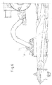
- FIG. 1 shows a wheel suspension 1, in particular a McPherson wheel suspension with a subframe 2 and a stabilizer 3.
- a lower wishbone 4 is in usually included in a damping unit 6.
- the damping unit 6 is mounted in a receptacle 7 connected to the subframe 2.
- Stabilizer 3 is seen in the transverse direction of the subframe 2 in outer End portions 10 of the subframe 2 connected thereto.
- the suspension 1 is symmetrical to a vehicle longitudinal axis X-X designed so that subsequently only one side of the suspension is described.
- the Damping unit 6 on a round outer circumference.
- the damping unit 6 is exemplified as a rubber bush and arranged horizontally.
- the receptacle 7 is made as a housing in one piece from a metal sheet and has an approximately circular receiving area 8, which in a connection area 9 passes ( Figure 2).
- the receiving area 8 has two vehicle longitudinal axes X-X spaced holding webs 11, between which a gap 12 is arranged.
- the Receiving area 8 comprises the damping unit 6 in its circumferential direction approximately three quarters, so that the connection region 9 is formed as a mouth 13.
- the retaining webs 11 In one Transition 14 to the mouth 13 are the retaining webs 11 each on their outer sides cone-shaped and widen in the direction of the connection area.
- the holding webs 11 each have on one side on outer sides 16 bends 17, which serve to reinforce the transition 14 to the connection area 9.
- connection region 9 has two in a vertical axis Z-Z spaced plane Attachment sections 18 and 19, wherein the reference numeral 18 is an upper and reference numeral 19 denotes a lower attachment portion (FIG 3).
- the attachment portions 18 and 19 are substantially rectangular designed and equally thick. The distance between the attachment sections 18 and 19, respectively in the mounted state preferably corresponds to a height of the subframe 2.
- the attachment portions 18 and 19 are made wider than the two Holding webs 11 with the interposed gap 12.
- Drilled holes introduced. When mounted, the holes are congruent arranged to openings in the subframe 2, so that an attachment of the Recording 7 on the subframe 2 is preferably done by means of bolts 20 bolts.
- a mounting portion is formed on the subframe 2, on which the Recording 7 is attached to the subframe 2.
- the receptacle 7 is preferably designed spring-like, so that the connection region 9 to different Heights is adaptable.
- the subframe 2 has an upper and a lower subframe shell 21 and 22, respectively on, so that to reinforce the attachment area reinforcing sleeves 23rd are arranged within the subframe 2 ( Figure 3).
- the upper one is Subframe shell 22 not shown in the attachment area to the arrangement represent the reinforcing sleeves 23.
- the stabilizer 3 is in particular via a terminal 24 on the receptacle 7 its upper attachment portion 18 is attached ( Figures 2 and 5).
- the clamp 24 is preferably U-shaped with U-legs 26 and a rounded base leg 27 configured ( Figure 5). At free ends of the U-legs 26 is one each Mounting flange 28 is arranged. In the mounting flange 28 is a respective for drilling in the mounting portions 18 corresponding bore brought in.
- the clamp 24 is arranged such that it the stabilizer. 3 includes.
- the mounting flanges 28 are preferably designed plan and with their holes congruent to the holes of the or the attachment sections 18 and the openings in the subframe 2.
- the mounting flanges 28 are preferably on the upper Attachment section 18.
- the stabilizer 3 is also provided with a guide means 29 comprises ( Figures 5 and 6).
- the guide means 29 causes in the mounted state a necessary stop of the stabilizer 3 and can also as Decoupling act.
- the guide means 29 is flexible, so that it on the one hand on an inner wall of the terminal 24 completely and on the plane Fixing section 12 rests flat.
- the stud bolts 20 are coming from the direction of the terminal 24 in Direction of a floor through the congruent holes or openings inserted, wherein the reinforcing sleeves 23 at the same time as a guide of the Bolt bolts 20 are used.
- the stud bolts 20 are with their head 31st each on the mounting flange 28 to protrude with its free threaded end 32nd over the lower mounting portion 19 in the direction of the ground.
- a mother 33 is used for frictional connection and secure attachment to the respective Threaded end 32 screwed. Of course, one can do that too opposite mounting direction of the bolts 20 may be provided.
- the damping unit 6 is different from FIGS. 1 to 3 designed as a hydro damper.
- the receptacle 7 has a circular Receiving area 8, and comprises the damping unit 6 in full.
- the Connection region 9 is thicker with its upper attachment portion 18 formed as the lower attachment portion 19. Accordingly, the respective transition 14 designed.
- the damping unit 6 after the Embodiment of Figures 4 to 9 is made of aluminum and is preferably designed as a one-piece extruded aluminum part.
- a length of a lever arm 34 of the stabilizer 3 advantageously only 190 mm. This is the lever arm 34 relatively short.
Landscapes
- Engineering & Computer Science (AREA)
- Mechanical Engineering (AREA)
- Chemical & Material Sciences (AREA)
- Combustion & Propulsion (AREA)
- Transportation (AREA)
- Vehicle Body Suspensions (AREA)
Abstract
Description
Die Erfindung betrifft eine Radaufhängung an Kraftfahrzeugen mit einem Hilfsrahmen und einem Stabilisator, wobei ein unterer Querlenker zumindest in einer Dämpfungseinheit aufgenommen ist, die in einer mit dem Hilfsrahmen verbindbaren Aufnahme gelagert ist.The invention relates to a suspension of motor vehicles with a subframe and a stabilizer, wherein a lower wishbone at least in one Damping unit is included, which can be connected in one with the subframe Recording is stored.
Derartige Radaufhängungen sind beispielsweise als McPherson-Radaufhängungen bekannt. Hierbei ist der Stabilisator jeweils mittels einer Klemme und zwei Bolzenschrauben beidseitig einer Fahrzeuglängsachse an dem Hilfsrahmen befestigt.Such suspensions are for example as McPherson suspension known. Here, the stabilizer is in each case by means of a clamp and two Bolt bolts on both sides of a vehicle longitudinal axis on the subframe attached.
Als ein Hauptnachteil der bekannten Radaufhängungen ist anzusehen, daß die Befestigung des Stabilisators an dem Hilfsrahmen in Querrichtung des Kraftfahrzeugs gesehen weit innerhalb, also näher an einer Fahrzeuglängsachse als die Dämpfungseinheit angeordnet ist. Bei bekannten Anordnungen weist ein Hebelarm des Stabilisators einen Längenbetrag von 281 mm auf. Dadurch ergibt sich ein schlechtes Ansprechverhalten, da der Hebelarm des Stabilisators relativ lang ist. Hierdurch werden hohe Belastungen auf den Hilfsrahmen ausgeübt, die eine Verstärkung erfordern um den Belastungen standzuhalten. Weiterhin erhöht das Biegemoment die Biegespannung im Stabilisatorrücken und den Radien, welche negative Einflüsse auf die Dauerhaltbarkeit des Stabilisators hat.As a major disadvantage of the known suspension is to be considered that the Attaching the stabilizer to the subframe in the transverse direction of the Motor vehicle seen far inside, so closer to a vehicle longitudinal axis than the damping unit is arranged. In known arrangements has a Lever arm of the stabilizer a length of 281 mm. This results a bad response, since the lever arm of the stabilizer is relatively long. As a result, high loads are exerted on the subframe, the one Require reinforcement to withstand the stresses. Furthermore, this increases Bending moment the bending stress in the stabilizer back and the radii, which has negative effects on the durability of the stabilizer.
Der Erfindung liegt die Aufgabe zugrunde, eine verbesserte Radaufhängung der Eingangs genannten Art zur Verfügung zustellen, welche mit einfachen Mitteln eine dynamische Leistungsentwicklung positiv beeinflußt und zugleich preiswerter herzustellen ist.The invention has the object of providing an improved suspension of the The aforementioned type to provide, which by simple means a dynamic performance development positively influenced and at the same time cheaper is to produce.
Erfindungsgemäß wird dies dadurch erreicht, daß der Stabilisator in Querrichtung des Hilfsrahmens gesehen in äußeren Endbereichen des Hilfsrahmens mit diesem verbunden ist. According to the invention this is achieved in that the stabilizer in the transverse direction of the subframe seen in outer end portions of the subframe with this connected is.
Der Erfindung liegt die Erkenntnis zugrunde, daß die Leistungsfähigkeit des Stabilisators von der Übersetzung zu einem Rad abhängt. Je größer die Übersetzung wird, erfolgt eine umso geringere Wankneigung eines Fahrzeugaufbaus. Mit der Erfindung wird vorteilhaft erreicht, daß ein Befestigungspunkt des Stabilisators möglichst weit außerhalb, also weit entfernt von der Fahrzeuglängsachse angeordnet ist, wodurch eine größere Übersetzung erreicht wird. Ein kleiner Hebelarm gewährleistet ein gutes Ansprechverhalten des Stabilisators.The invention is based on the finding that the performance of the Stabilizer depends on the translation to a wheel. The bigger the translation is, there is an even lower tendency to roll of a vehicle body. With the Invention is advantageously achieved that an attachment point of the stabilizer as far outside, so far away from the vehicle's longitudinal axis is, whereby a larger translation is achieved. A small lever arm ensures a good response of the stabilizer.
Um eine einfache Befestigung sicherzustellen, ist es zweckmäßig, wenn der Stabilisator über einen für die Verbindung der Aufnahme mit dem Hilfsrahmen vorgesehenen Befestigungsbereich mit dem Hilfsrahmen verbunden ist. Der Befestigungsbereich weist die notwendigen Öffnungen auf, durch die eine kraftformschlüssige Verbindung des Stabilisators mit dem Hilfsrahmen herstellbar ist. Dies ist beispielsweise bei horizontal angeordneten unteren Querlenkern denkbar, bei dem der Stabilisator direkt mit dem Hilfsrahmen verbindbar ist, indem die gleichen Öffnungen genutzt werden, die für die Montage der Aufnahme vorgesehen sind.To ensure easy attachment, it is useful if the Stabilizer over one for connecting the intake with the subframe provided mounting area is connected to the subframe. Of the Mounting area has the necessary openings through which a kraftformschlüssige connection of the stabilizer with the subframe is produced. This is conceivable, for example, in horizontally arranged lower wishbones in which the stabilizer is directly connectable to the subframe by the same openings are used, which provided for the mounting of the recording are.
Günstig im Sinne der Erfindung ist, wenn der Stabilisator über die Aufnahme mit dem Hilfsrahmen verbunden ist. Hierbei ist die Aufnahme in dem dafür vorgesehenen Befestigungsbereich mit dem Hilfsrahmen verbunden. Der Stabilisator ist gleichzeitig mit denselben Verbindungsmitteln wie die Aufnahme mit dem Hilfsrahmen verbunden. Die ist beispielsweise bei Dämpfungseinheiten, die als konventionelle Gummibuchse oder Hydrobuchse ausgestaltet und vorzugsweise horizontal angeordnet sind denkbar.Favorable for the purposes of the invention is when the stabilizer on the recording with the Subframe is connected. Here is the recording in the designated Attachment area connected to the subframe. The stabilizer is at the same time with the same connection means as the subframe mount connected. This is for example in damping units that conventional Rubber bush or hydraulic bush designed and preferably horizontal arranged are conceivable.
Um den Stabilisator mit der Aufnahme der Dämpfungseinheit oder mit dem Hilfsrahmen zu verbinden, ist es günstig im Sinne der Erfindung, wenn der Stabilisator von einer Klemme zumindest teilweise umfaßt wird. Zweckmäßig ist, wenn die Klemme u-förmig ausgestaltet ist, wobei an freien Enden jeweiliger u-Schenkel jeweils ein Befestigungsflansch angeordnet ist. In dem jeweiligen Befestigungsflansch ist vorteilhaft eine Bohrung zur Durchführung der Verbindungsmittel, vorzugsweise von Bolzenschrauben eingebracht. Vorteilhafter Weise sind die Bohrungen an die Verbindungsmittel zur Verbindung der Aufnahme des Dämpfungsmittels an dem Hilfsrahmen angepaßt.To the stabilizer with the inclusion of the damping unit or with the To connect subframe, it is favorable in the context of the invention, when the Stabilizer is at least partially covered by a clamp. It is expedient when the clamp is U-shaped, with free ends of respective u-legs in each case a mounting flange is arranged. In the respective Mounting flange is advantageously a bore for carrying the Connecting means, preferably introduced by stud bolts. Favorable Way are the holes to the connecting means for connecting the recording the damping means adapted to the subframe.
Der Stabilisator weist einen geringeren Durchmesser als die Klemme auf. Damit der Stabilisator genügend befestigt ist, wird dieser vorteilhaft von einem Führungsmittel umfaßt, daß etwas größer als eine lichte Öffnung der Klemme ist. Damit wird der Stabilisator im angezogenen Zustand der Verbindungsmittel hinreichend gehalten. Selbstverständlich kann das Führungsmittel auch schwingungsdämpfende Eigenschaften aufweisen.The stabilizer has a smaller diameter than the clamp. So the Stabilizer is sufficiently secured, this is beneficial from a guide means that is slightly larger than a clear opening of the clamp. This will be the Stabilizer sufficiently kept in the attracted state of the connecting means. Of course, the guide means also vibration damping Have properties.
Mit der erfindungsgemäßen Radaufhängung ist eine bestmögliche
Stabilisatorübersetzung erreichbar, da eine Verbindung des Stabilisators mit dem
Hilfsrahmen weit entfernt von der Fahrzeuglängsachse angeordnet ist, und zwar
vorzugsweise an dem Befestigungsbereich, an dem die Aufnahme des
Dämpfungselementes vorgesehen ist. Der Befestigungsbereich ist hierbei ein
sogenannter Punkt 4. Punkt 4 ist ein geometrischer Punkt der Fahrwerksauslegung,
der einen geometrischen Punkt einer hinteren Dämpfungseinheit eines unteren
Querlenkers bei McPherson-Aufhängungen darstellt. Dadurch, daß die Befestigung
des Stabilisators sehr weit außerhalb angeordnet ist, erhöht sich die Stabilisatorrate
(N/Grad oder N/rad), so daß der Stabilisator mit einem verringerten Durchmesser
hergestellt werden kann, wodurch sowohl an Gewicht als auch an
Herstellungskosten eingespart werden kann. Damit kann vorteilhaft eine gewünschte
Rollrate erzielt werden. Die Rollrate ist ein Winkel eines Fahrzeugaufbaus im
Verhältnis zur Seitenkraft, insbesondere einer Zentrifugalkraft, also ein Wert zur
Bestimmung der Aufbauneigung. Weiterhin reduziert sich eine Vergleichsspannung,
die von Torsions- und Biegemomenten abhängig ist. Dies wirkt sich positiv auf eine
Verlängerung der Lebensdauer des Stabilisators aus. Die Vergleichspannung kann
beispielsweise nach der Gestaltänderungshypothese in üblicher Weise berechnet
werden, um die zu erwartende Lebensdauer abzuschätzen.With the suspension according to the invention is the best possible
Stabilizer translation achievable because a compound of the stabilizer with the
Subframe is located far away from the vehicle's longitudinal axis, namely
Preferably, at the attachment area at which the inclusion of the
Damping element is provided. The attachment area is here
so-called
Zudem kann auf eine gesonderte Befestigung und somit auf nicht mehr notwendige Bauteile verzichtet werden. Wurde im Stand der Technik der Stabilisator mit jeweils separaten Schrauben und Muttern befestigt, kann bei der erfindungsgemäßen Radaufhängung hierauf vorteilhaft verzichtet werden. Dies erspart zudem eine aufwendige Materiallogistik unterschiedlicher und vielfältiger Bauteile. Selbstverständlich entfällt dabei zusätzlich eine kostenintensive Herstellung von Schraubenlöchern in dem Hilfsrahmen, die zur Aufnahme der Schrauben erforderlich waren.In addition, a separate attachment and thus no longer necessary Components are dispensed with. Was in the prior art, the stabilizer with each attached separate screws and nuts, can in the inventive Wheel suspension can be advantageously dispensed with. This also saves a complex material logistics of different and diverse components. Of course, this also eliminates a costly production of Bolt holes in the subframe required to receive the screws were.
Weitere Vorteilhafte Ausgestaltungen der Erfindung sind in den Unteransprüchen und der folgenden Figurenbeschreibung offenbart. Es zeigen:
- Fig. 1
- eine perspektivische Gesamtansicht einer Radaufhängung,
- Fig. 2
- eine Vergrößerung des gekennzeichneten Bereiches aus Figur 1,
- Fig. 3
- einen Teilschnitt aus
Figur 2, - Fig. 4
- eine Explosionsdarstellung mit einer Ausführungsform einer Aufnahme,
- Fig. 5
- eine perspektivische Ansicht aus
Figur 4, - Fig. 6
- eine Seitenansicht aus
Figur 4, - Fig. 7
- eine perspektivische Seitenansicht aus
Figur 4, - Fig. 8
- eine Hinteransicht aus
Figur 4, - Fig. 9
- eine Draufsicht aus
Figur 4.
- Fig. 1
- an overall perspective view of a suspension,
- Fig. 2
- an enlargement of the marked area of FIG. 1,
- Fig. 3
- a partial section of Figure 2,
- Fig. 4
- an exploded view with an embodiment of a recording,
- Fig. 5
- a perspective view of Figure 4,
- Fig. 6
- a side view of Figure 4,
- Fig. 7
- a perspective side view of Figure 4,
- Fig. 8
- a rear view of Figure 4,
- Fig. 9
- a plan view of Figure 4.
In den unterschiedlichen Figuren sind gleiche Teile mit denselben Bezugszeichen versehen, weswegen diese in der Regel auch nur einmal beschrieben werden.In the different figures, like parts are given the same reference numerals which is why they are usually described only once.
Figur 1 zeigt eine Radaufhängung 1, insbesondere eine McPherson-Radaufhängung
mit einem Hilfsrahmen 2 und einem Stabilisator 3. Ein unterer Querlenker 4 ist in
üblicher Weise in einer Dämpfungseinheit 6 aufgenommen. Die Dämpfungseinheit 6
ist in einer mit dem Hilfsrahmen 2 verbundenen Aufnahme 7 gelagert. Der
Stabilisator 3 ist in Querrichtung des Hilfsrahmens 2 gesehen in äußeren
Endbereichen 10 des Hilfsrahmens 2 mit diesem verbunden.FIG. 1 shows a wheel suspension 1, in particular a McPherson wheel suspension
with a
Die Radaufhängung 1 ist symmetrisch zu einer Fahrzeuglängsachse X-X ausgestaltet, so daß nachfolgend lediglich eine Seite der Radaufhängung beschrieben wird.The suspension 1 is symmetrical to a vehicle longitudinal axis X-X designed so that subsequently only one side of the suspension is described.
In dem in den Figuren 1 bis 3 dargestellten Ausführungsbeispiel weist die
Dämpfungseinheit 6 einen runden Außenumfang auf. Die Dämpfungseinheit 6 ist
beispielhaft als Gummibuchse ausgestaltet und horizontal angeordnet.In the embodiment shown in Figures 1 to 3, the
Damping
Die Aufnahme 7 ist als Gehäuse einstückig aus einem Blech hergestellt und weist
einen in etwa kreisförmigen Aufnahmebereich 8 auf, der in einen Anbindungsbereich
9 übergeht (Figur 2). Der Aufnahmebereich 8 weist zwei in Fahrzeuglängsachse X-X
beabstandete Haltestege 11 auf, zwischen denen ein Spalt 12 angeordnet ist. Der
Aufnahmebereich 8 umfaßt die Dämpfungseinheit 6 in ihrer Umfangsrichtung in etwa
dreiviertel, so daß der Anbindungsbereich 9 als Maul 13 ausgebildet ist. In einem
Übergang 14 zum Maul 13 sind die Haltestege 11 jeweils an ihren Außenseiten
konusförmig ausgebildet und verbreitern sich in Richtung zum Anbindungsbereich 9.
Die Haltestege 11 weisen jeweils einseitig an Außenseiten 16 Aufbiegungen 17 auf,
die zur Verstärkung des Übergangs 14 zum Anbindungsbereich 9 dienen.The
Der Anbindungsbereich 9 weist zwei in einer Hochachse Z-Z beabstandete ebene
Befestigungsabschnitte 18 und 19 auf, wobei das Bezugszeichen 18 einen oberen
und das Bezugszeichen 19 einen unteren Befestigungsabschnitt bezeichnet (Figur
3). Die Befestigungsabschnitte 18 bzw. 19 sind im wesentlichen rechteckig
ausgestaltet und gleich dick. Der Abstand der Befestigungsabschnitte 18 bzw. 19
entspricht im montierten Zustand vorzugsweise einer Bauhöhe des Hilfsrahmens 2.
Die Befestigungsabschnitte 18 bzw. 19 sind breiter ausgestaltet als die beiden
Haltestege 11 mit dem dazwischen angeordneten Spalt 12. In den
Befestigungsabschnitten 18 bzw. 19 sind in Fahrzeuglängsrichtung beabstandete
Bohrungen eingebracht. Im montierten Zustand sind die Bohrungen deckungsgleich
zu Öffnungen in dem Hilfsrahmen 2 angeordnet, so daß eine Befestigung der
Aufnahme 7 an dem Hilfsrahmen 2 vorzugsweise mittels Bolzenschrauben 20 erfolgt. The connection region 9 has two in a vertical axis Z-Z spaced
Damit ist ein Befestigungsbereich an dem Hilfsrahmen 2 gebildet, an dem die
Aufnahme 7 an dem Hilfsrahmen 2 befestigt ist. Die Aufnahme 7 ist vorzugsweise
federähnlich ausgestaltet, so daß der Anbindungsbereich 9 an unterschiedliche
Bauhöhen anpaßbar ist.Thus, a mounting portion is formed on the
Der Hilfsrahmen 2 weist eine obere und eine untere Hilfsrahmenschale 21 bzw. 22
auf, so daß zur Verstärkung des Befestigungsbereiches Verstärkungshülsen 23
innerhalb des Hilfsrahmens 2 angeordnet sind (Figur 3). In Figur 3 ist die obere
Hilfsrahmenschale 22 im Befestigungsbereich nicht dargestellt, um die Anordnung
der Verstärkungshülsen 23 darzustellen.The
Der Stabilisator 3 ist über eine Klemme 24 an der Aufnahme 7 insbesondere an
ihrem oberen Befestigungsabschnitt 18 befestigt (Figuren 2 und 5). Die Klemme 24
ist vorzugsweise u-förmig mit U-Schenkeln 26 und einem verrundeten Basisschenkel
27 ausgestaltet (Figur 5). An freien Enden der U-Schenkel 26 ist jeweils ein
Befestigungsflansch 28 angeordnet. In dem Befestigungsflansch 28 ist jeweils eine
zur Bohrung in den Befestigungsabschnitten 18 korrespondierende Bohrung
eingebracht. Die Klemme 24 ist derart angeordnet, daß diese den Stabilisator 3
umfaßt. Die Befestigungsflanschen 28 sind vorzugsweise plan ausgestaltet und mit
ihren Bohrungen kongruent zu den Bohrungen des bzw. der Befestigungsabschnitte
18 sowie der Öffnungen in dem Hilfsrahmen 2.The
In dem in den Figuren 1 bis 3 sowie 4 bis 9 dargestellten Ausführungsbeispielen
liegen die Befestigungsflansche 28 vorzugsweise auf dem oberen
Befestigungsabschnitt 18 auf.In the embodiments illustrated in Figures 1 to 3 and 4 to 9
the mounting
Im Bereich der Klemme 24 ist der Stabilisator 3 zudem von einem Führungsmittel 29
umfaßt (Figuren 5 und 6). Das Führungsmittel 29 bewirkt im montierten Zustand
einen notwendigen Halt des Stabilisators 3 und kann zudem auch als
Entkopplungsmittel wirken. Das Führungsmittel 29 ist flexibel ausgestaltet, so daß es
zum einen an einer Innenwand der Klemme 24 vollständig und an dem ebenen
Befestigungsabschnitt 12 plan aufliegt. In the area of the
Die Bolzenschrauben 20 werden aus der Richtung von der Klemme 24 kommend in
Richtung eines Bodens durch die deckungsgleichen Bohrungen bzw. Öffnungen
gesteckt, wobei die Verstärkungshülsen 23 gleichzeitig als Führung der
Bolzenschrauben 20 dienen. Die Bolzenschrauben 20 liegen mit ihrem Kopf 31
jeweils auf dem Befestigungsflansch 28 auf ragen mit ihrem freien Gewindeende 32
über den unteren Befestigungsabschnitt 19 in Richtung zum Boden. Eine Mutter 33
wird zur kraftformschlüssigen Verbindung und sicheren Befestigung jeweils auf das
Gewindeende 32 aufgeschraubt. Selbstverständlich kann auch eine dazu
entgegengesetzte Montagerichtung der Bolzenschrauben 20 vorgesehen sein.The
In den Figuren 4 bis 9 ist die Dämpfungseinheit 6 im Unterschied zu Figuren 1 bis 3
als Hydrodämpfer ausgelegt. Die Aufnahme 7 weist einen kreisförmigen
Aufnahmebereich 8 auf, und umfaßt die Dämpfungseinheit 6 vollumfänglich. Der
Anbindungsbereich 9 ist mit seinem oberen Befestigungsabschnitt 18 dicker
ausgebildet als der untere Befestigungsabschnitt 19. Dementsprechend ist der
jeweilige Übergang 14 gestaltet. Die Dämpfungseinheit 6 nach dem
Ausführungsbeispiel der Figuren 4 bis 9 besteht aus Aluminium und ist vorzugsweise
als einstückiges Aluminium Strangpressteil ausgestaltet.In FIGS. 4 to 9, the damping
Bei den dargestellten Ausführungsbeispielen beträgt eine Länge eines Hebelarms
34 des Stabilisators 3 vorteilhafter Weise lediglich 190 mm. Damit ist der Hebelarm
34 relativ kurz.In the illustrated embodiments, a length of a
Claims (6)
dadurch gekennzeichnet, daß
der Stabilisator (3) in Querrichtung des Hilfsrahmens (2) gesehen in äußeren Endbereichen (10) des Hilfsrahmens (2) mit diesem verbunden ist.Wheel suspension on motor vehicles with a subframe (2) and a stabilizer (3), wherein a lower transverse link (4) is accommodated at least in a damping unit (6) which is mounted in a receptacle (7) connectable to the subframe (2),
characterized in that
the stabilizer (3), seen in the transverse direction of the subframe (2), is connected to the auxiliary frame (2) in outer end regions (10) thereof.
dadurch gekennzeichnet, daß
der Stabilisator (3) mit einem für die Verbindung der Aufnahme (7) mit dem Hilfsrahmen (2) vorgesehenen Befestigungsbereich mit dem Hilfsrahmen (2) verbunden ist.Wheel suspension according to claim 1,
characterized in that
the stabilizer (3) is connected to a fastening area provided with the subframe (2) for connecting the receptacle (7) to the subframe (2).
dadurch gekennzeichnet, daß
der Stabilisator (3) kraftformschlüssig über die Aufnahme (7) mit dem Hilfsrahmen (2) verbunden ist.Wheel suspension according to claim 1 or 2,
characterized in that
the stabilizer (3) is positively frictionally connected via the receptacle (7) with the subframe (2).
dadurch gekennzeichnet, daß
der Stabilisator (3) zumindest teilweise von einer Klemme (24) umfaßt wird, die u-förmig mit U-Schenkeln (26) und einem verrundeten Basissteg (27) ausgestaltet ist.Wheel suspension according to one of the preceding claims,
characterized in that
the stabilizer (3) is at least partially enclosed by a clamp (24) which is U-shaped with U-legs (26) and a rounded base web (27).
dadurch gekennzeichnet, daß
die Klemme (24) an freien Enden ihrer U-Schenkel (26) Befestigungsflansche (28) aufweist, in denen Bohrungen eingebracht sind. Wheel suspension according to claim 4,
characterized in that
the clamp (24) at free ends of their U-legs (26) mounting flanges (28), in which bores are introduced.
dadurch gekennzeichnet, daß
der Stabilisator (3) in einem Klemmenbereich von einem Führungsmittel (29) umgeben ist.Wheel suspension according to one of the preceding claims,
characterized in that
the stabilizer (3) is surrounded in a terminal region by a guide means (29).
Priority Applications (2)
| Application Number | Priority Date | Filing Date | Title |
|---|---|---|---|
| DE50305059T DE50305059D1 (en) | 2003-11-21 | 2003-11-21 | Independent wheel suspension for a motor vehicle |
| EP20030104310 EP1533151B1 (en) | 2003-11-21 | 2003-11-21 | Motor vehicle independent wheel suspension |
Applications Claiming Priority (1)
| Application Number | Priority Date | Filing Date | Title |
|---|---|---|---|
| EP20030104310 EP1533151B1 (en) | 2003-11-21 | 2003-11-21 | Motor vehicle independent wheel suspension |
Publications (2)
| Publication Number | Publication Date |
|---|---|
| EP1533151A1 true EP1533151A1 (en) | 2005-05-25 |
| EP1533151B1 EP1533151B1 (en) | 2006-09-13 |
Family
ID=34429513
Family Applications (1)
| Application Number | Title | Priority Date | Filing Date |
|---|---|---|---|
| EP20030104310 Expired - Lifetime EP1533151B1 (en) | 2003-11-21 | 2003-11-21 | Motor vehicle independent wheel suspension |
Country Status (2)
| Country | Link |
|---|---|
| EP (1) | EP1533151B1 (en) |
| DE (1) | DE50305059D1 (en) |
Cited By (10)
| Publication number | Priority date | Publication date | Assignee | Title |
|---|---|---|---|---|
| KR100610115B1 (en) | 2004-10-29 | 2006-08-09 | 현대자동차주식회사 | Stabilizer bar mounting structure of automobile |
| JP2007182116A (en) * | 2006-01-05 | 2007-07-19 | Mitsubishi Automob Eng Co Ltd | Vehicle stabilizer mounting structure |
| EP2017163A2 (en) | 2007-06-18 | 2009-01-21 | Nissan Motor Co., Ltd. | Vehicle body front part structure |
| JP2010089549A (en) * | 2008-10-03 | 2010-04-22 | Honda Motor Co Ltd | Stabilizer mounting structure |
| CN101327811B (en) * | 2007-06-18 | 2010-06-02 | 日产自动车株式会社 | Vehicle body front part structure |
| DE102015223280A1 (en) * | 2015-11-25 | 2017-06-01 | Bayerische Motoren Werke Aktiengesellschaft | Axle of a motor vehicle with an electric motor drive unit suspended in the axle carrier |
| CN108749501A (en) * | 2018-04-24 | 2018-11-06 | 北京新能源汽车股份有限公司 | Suspension for vehicle and vehicle |
| US10207562B2 (en) * | 2015-09-09 | 2019-02-19 | Toyota Jidosha Kabushiki Kaisha | Stabilizer support structure |
| US20190299736A1 (en) * | 2018-03-27 | 2019-10-03 | Kawasaki Jukogyo Kabushiki Kaisha | Attaching structure for stabilizer of utility vehicle |
| DE102019201731B3 (en) * | 2019-02-11 | 2020-03-12 | Audi Ag | Mounting arrangement for a stabilizer of a motor vehicle |
Families Citing this family (1)
| Publication number | Priority date | Publication date | Assignee | Title |
|---|---|---|---|---|
| JP6269638B2 (en) * | 2015-11-11 | 2018-01-31 | マツダ株式会社 | Rear subframe structure |
Citations (13)
| Publication number | Priority date | Publication date | Assignee | Title |
|---|---|---|---|---|
| EP0477654A2 (en) * | 1990-09-26 | 1992-04-01 | Mazda Motor Corporation | Front body structure of automotive vehicle |
| US5707074A (en) * | 1994-11-04 | 1998-01-13 | Nissan Motor Co., Ltd. | Stabilizer support structure |
| JPH10258763A (en) * | 1997-03-18 | 1998-09-29 | Nissan Motor Co Ltd | Suspension subframe structure |
| JPH11334332A (en) * | 1998-05-28 | 1999-12-07 | Daihatsu Motor Co Ltd | Front suspension |
| JP2000071734A (en) * | 1998-09-02 | 2000-03-07 | Mazda Motor Corp | Vehicle suspension support structure |
| US6085856A (en) * | 1998-12-16 | 2000-07-11 | Daimlerchrysler Corporation | Attachment system for suspension cradle |
| FR2788822A1 (en) * | 1999-01-25 | 2000-07-28 | Paulstra Gmbh | Hydraulic vibration isolating support for machinery or road vehicle suspension has fluid filled chambers in elastomeric bush joining inner and outer bushes |
| DE19920051A1 (en) * | 1999-05-03 | 2000-11-16 | Porsche Ag | Vehicle front axle subframe, with side bearers connected to cross bearers mounted on them and with receivers for elastic support bearings |
| WO2001040008A1 (en) * | 1999-11-29 | 2001-06-07 | Cosma International Inc. | Vehicle component mounting assembly |
| JP2001171326A (en) * | 1999-12-17 | 2001-06-26 | Nissan Motor Co Ltd | Suspension structure |
| FR2810275A1 (en) * | 2000-06-14 | 2001-12-21 | Peugeot Citroen Automobiles Sa | Support mounting, for torsion bar of vehicle axle, consists of stirrup bracket, with two branches, carrying support on linking wall and attaching to vehicle structure by means of locating projections. |
| JP2003205852A (en) * | 2002-01-15 | 2003-07-22 | Nissan Motor Co Ltd | Vehicle sub-frame |
| EP1362767A2 (en) * | 2002-05-14 | 2003-11-19 | Dr.Ing. h.c.F. Porsche Aktiengesellschaft | Motor vehicle front suspension sub-frame |
-
2003
- 2003-11-21 EP EP20030104310 patent/EP1533151B1/en not_active Expired - Lifetime
- 2003-11-21 DE DE50305059T patent/DE50305059D1/en not_active Expired - Lifetime
Patent Citations (13)
| Publication number | Priority date | Publication date | Assignee | Title |
|---|---|---|---|---|
| EP0477654A2 (en) * | 1990-09-26 | 1992-04-01 | Mazda Motor Corporation | Front body structure of automotive vehicle |
| US5707074A (en) * | 1994-11-04 | 1998-01-13 | Nissan Motor Co., Ltd. | Stabilizer support structure |
| JPH10258763A (en) * | 1997-03-18 | 1998-09-29 | Nissan Motor Co Ltd | Suspension subframe structure |
| JPH11334332A (en) * | 1998-05-28 | 1999-12-07 | Daihatsu Motor Co Ltd | Front suspension |
| JP2000071734A (en) * | 1998-09-02 | 2000-03-07 | Mazda Motor Corp | Vehicle suspension support structure |
| US6085856A (en) * | 1998-12-16 | 2000-07-11 | Daimlerchrysler Corporation | Attachment system for suspension cradle |
| FR2788822A1 (en) * | 1999-01-25 | 2000-07-28 | Paulstra Gmbh | Hydraulic vibration isolating support for machinery or road vehicle suspension has fluid filled chambers in elastomeric bush joining inner and outer bushes |
| DE19920051A1 (en) * | 1999-05-03 | 2000-11-16 | Porsche Ag | Vehicle front axle subframe, with side bearers connected to cross bearers mounted on them and with receivers for elastic support bearings |
| WO2001040008A1 (en) * | 1999-11-29 | 2001-06-07 | Cosma International Inc. | Vehicle component mounting assembly |
| JP2001171326A (en) * | 1999-12-17 | 2001-06-26 | Nissan Motor Co Ltd | Suspension structure |
| FR2810275A1 (en) * | 2000-06-14 | 2001-12-21 | Peugeot Citroen Automobiles Sa | Support mounting, for torsion bar of vehicle axle, consists of stirrup bracket, with two branches, carrying support on linking wall and attaching to vehicle structure by means of locating projections. |
| JP2003205852A (en) * | 2002-01-15 | 2003-07-22 | Nissan Motor Co Ltd | Vehicle sub-frame |
| EP1362767A2 (en) * | 2002-05-14 | 2003-11-19 | Dr.Ing. h.c.F. Porsche Aktiengesellschaft | Motor vehicle front suspension sub-frame |
Non-Patent Citations (6)
| Title |
|---|
| PATENT ABSTRACTS OF JAPAN vol. 013, no. 274 (M - 841) 23 June 1989 (1989-06-23) * |
| PATENT ABSTRACTS OF JAPAN vol. 1998, no. 14 31 December 1998 (1998-12-31) * |
| PATENT ABSTRACTS OF JAPAN vol. 2000, no. 03 30 March 2000 (2000-03-30) * |
| PATENT ABSTRACTS OF JAPAN vol. 2000, no. 06 22 September 2000 (2000-09-22) * |
| PATENT ABSTRACTS OF JAPAN vol. 2000, no. 23 10 February 2001 (2001-02-10) * |
| PATENT ABSTRACTS OF JAPAN vol. 2003, no. 11 5 November 2003 (2003-11-05) * |
Cited By (13)
| Publication number | Priority date | Publication date | Assignee | Title |
|---|---|---|---|---|
| KR100610115B1 (en) | 2004-10-29 | 2006-08-09 | 현대자동차주식회사 | Stabilizer bar mounting structure of automobile |
| JP2007182116A (en) * | 2006-01-05 | 2007-07-19 | Mitsubishi Automob Eng Co Ltd | Vehicle stabilizer mounting structure |
| CN101327811B (en) * | 2007-06-18 | 2010-06-02 | 日产自动车株式会社 | Vehicle body front part structure |
| EP2017163A3 (en) * | 2007-06-18 | 2009-05-06 | Nissan Motor Co., Ltd. | Vehicle body front part structure |
| US7726672B2 (en) | 2007-06-18 | 2010-06-01 | Nissan Motor Co., Ltd. | Vehicle body front part structure |
| EP2017163A2 (en) | 2007-06-18 | 2009-01-21 | Nissan Motor Co., Ltd. | Vehicle body front part structure |
| JP2010089549A (en) * | 2008-10-03 | 2010-04-22 | Honda Motor Co Ltd | Stabilizer mounting structure |
| US10207562B2 (en) * | 2015-09-09 | 2019-02-19 | Toyota Jidosha Kabushiki Kaisha | Stabilizer support structure |
| DE102015223280A1 (en) * | 2015-11-25 | 2017-06-01 | Bayerische Motoren Werke Aktiengesellschaft | Axle of a motor vehicle with an electric motor drive unit suspended in the axle carrier |
| US20190299736A1 (en) * | 2018-03-27 | 2019-10-03 | Kawasaki Jukogyo Kabushiki Kaisha | Attaching structure for stabilizer of utility vehicle |
| US10661626B2 (en) * | 2018-03-27 | 2020-05-26 | Kawasaki Jukogyo Kabushiki Kaisha | Attaching structure for stabilizer of utility vehicle |
| CN108749501A (en) * | 2018-04-24 | 2018-11-06 | 北京新能源汽车股份有限公司 | Suspension for vehicle and vehicle |
| DE102019201731B3 (en) * | 2019-02-11 | 2020-03-12 | Audi Ag | Mounting arrangement for a stabilizer of a motor vehicle |
Also Published As
| Publication number | Publication date |
|---|---|
| DE50305059D1 (en) | 2006-10-26 |
| EP1533151B1 (en) | 2006-09-13 |
Similar Documents
| Publication | Publication Date | Title |
|---|---|---|
| EP1912806B2 (en) | Wheel suspension arm | |
| DE10053411B4 (en) | vehicle axle | |
| DE10032961B4 (en) | Torsion bar | |
| DE10031454B4 (en) | Torsion bar | |
| EP2982529B1 (en) | Pneumatic support for a pneumatically supported axle of a commercial vehicle | |
| WO2000051833A1 (en) | Axle suspension of rigid axles | |
| DE102010036731B4 (en) | Pendulum support assembly unit for a shock absorber | |
| DE3902407C1 (en) | Bearing | |
| EP3192680A1 (en) | Suspension arm of steel comprising a spring seat | |
| DE10110332A1 (en) | Vehicle has towing eye fitted in bumper by fixed mounting and detachable mounting spaced away from latter, each mounting consisting of through-opening constructed in rear and forward wall of bumper's cross support | |
| DE69817174T2 (en) | DEVICE FOR SUSPENSION | |
| EP1533151B1 (en) | Motor vehicle independent wheel suspension | |
| DE102017214190A1 (en) | Bearing arrangement for a motor vehicle | |
| DE10042594B4 (en) | Construction for suspension system attachment portions of a vehicle body | |
| DE69812083T2 (en) | MOUNTING SYSTEM | |
| DE19923698A1 (en) | Wishbones | |
| DE102017211277B4 (en) | Wheel suspension for a motor vehicle | |
| EP0940319A2 (en) | Chassis of a heavy utility vehicle | |
| DE10233826B4 (en) | Mounting arrangement of a spring and / or damper element on a hollow support of a motor vehicle body | |
| DE29519965U1 (en) | Motor vehicle wheel carrier for multi-link axles | |
| EP0940324B1 (en) | Chassis for a heavy-duty utility vehicle | |
| DE202018004756U1 (en) | Connecting device of a suspension | |
| EP1925470A2 (en) | Wheel suspension | |
| DE10247503B4 (en) | Storage of a vehicle vibration damper | |
| DE102018118340B4 (en) | Commercial vehicle axle suspension |
Legal Events
| Date | Code | Title | Description |
|---|---|---|---|
| PUAI | Public reference made under article 153(3) epc to a published international application that has entered the european phase |
Free format text: ORIGINAL CODE: 0009012 |
|
| AK | Designated contracting states |
Kind code of ref document: A1 Designated state(s): AT BE BG CH CY CZ DE DK EE ES FI FR GB GR HU IE IT LI LU MC NL PT RO SE SI SK TR |
|
| AX | Request for extension of the european patent |
Extension state: AL LT LV MK |
|
| 17P | Request for examination filed |
Effective date: 20051125 |
|
| AKX | Designation fees paid |
Designated state(s): DE FR GB |
|
| GRAP | Despatch of communication of intention to grant a patent |
Free format text: ORIGINAL CODE: EPIDOSNIGR1 |
|
| GRAS | Grant fee paid |
Free format text: ORIGINAL CODE: EPIDOSNIGR3 |
|
| GRAA | (expected) grant |
Free format text: ORIGINAL CODE: 0009210 |
|
| AK | Designated contracting states |
Kind code of ref document: B1 Designated state(s): DE FR GB |
|
| REG | Reference to a national code |
Ref country code: GB Ref legal event code: FG4D Free format text: NOT ENGLISH |
|
| REF | Corresponds to: |
Ref document number: 50305059 Country of ref document: DE Date of ref document: 20061026 Kind code of ref document: P |
|
| GBT | Gb: translation of ep patent filed (gb section 77(6)(a)/1977) |
Effective date: 20070108 |
|
| ET | Fr: translation filed | ||
| PLBE | No opposition filed within time limit |
Free format text: ORIGINAL CODE: 0009261 |
|
| STAA | Information on the status of an ep patent application or granted ep patent |
Free format text: STATUS: NO OPPOSITION FILED WITHIN TIME LIMIT |
|
| 26N | No opposition filed |
Effective date: 20070614 |
|
| REG | Reference to a national code |
Ref country code: FR Ref legal event code: PLFP Year of fee payment: 13 |
|
| REG | Reference to a national code |
Ref country code: FR Ref legal event code: PLFP Year of fee payment: 14 |
|
| REG | Reference to a national code |
Ref country code: FR Ref legal event code: PLFP Year of fee payment: 15 |
|
| REG | Reference to a national code |
Ref country code: FR Ref legal event code: PLFP Year of fee payment: 16 |
|
| PGFP | Annual fee paid to national office [announced via postgrant information from national office to epo] |
Ref country code: DE Payment date: 20191017 Year of fee payment: 17 |
|
| PGFP | Annual fee paid to national office [announced via postgrant information from national office to epo] |
Ref country code: FR Payment date: 20191029 Year of fee payment: 17 |
|
| PGFP | Annual fee paid to national office [announced via postgrant information from national office to epo] |
Ref country code: GB Payment date: 20191029 Year of fee payment: 17 |
|
| REG | Reference to a national code |
Ref country code: DE Ref legal event code: R119 Ref document number: 50305059 Country of ref document: DE |
|
| GBPC | Gb: european patent ceased through non-payment of renewal fee |
Effective date: 20201121 |
|
| PG25 | Lapsed in a contracting state [announced via postgrant information from national office to epo] |
Ref country code: FR Free format text: LAPSE BECAUSE OF NON-PAYMENT OF DUE FEES Effective date: 20201130 |
|
| PG25 | Lapsed in a contracting state [announced via postgrant information from national office to epo] |
Ref country code: GB Free format text: LAPSE BECAUSE OF NON-PAYMENT OF DUE FEES Effective date: 20201121 Ref country code: DE Free format text: LAPSE BECAUSE OF NON-PAYMENT OF DUE FEES Effective date: 20210601 |