EP1531533A1 - Versorgungsschaltung zur permanenten Versorgung eines Verbrauchers über eine schaltbare Leitung - Google Patents
Versorgungsschaltung zur permanenten Versorgung eines Verbrauchers über eine schaltbare Leitung Download PDFInfo
- Publication number
- EP1531533A1 EP1531533A1 EP04026495A EP04026495A EP1531533A1 EP 1531533 A1 EP1531533 A1 EP 1531533A1 EP 04026495 A EP04026495 A EP 04026495A EP 04026495 A EP04026495 A EP 04026495A EP 1531533 A1 EP1531533 A1 EP 1531533A1
- Authority
- EP
- European Patent Office
- Prior art keywords
- load
- circuit
- consumer
- supply
- rectifier
- Prior art date
- Legal status (The legal status is an assumption and is not a legal conclusion. Google has not performed a legal analysis and makes no representation as to the accuracy of the status listed.)
- Granted
Links
Images

Classifications
-
- H—ELECTRICITY
- H02—GENERATION; CONVERSION OR DISTRIBUTION OF ELECTRIC POWER
- H02J—ELECTRIC POWER NETWORKS; CIRCUIT ARRANGEMENTS OR SYSTEMS FOR SUPPLYING OR DISTRIBUTING ELECTRIC POWER; SYSTEMS FOR STORING ELECTRIC ENERGY
- H02J3/00—Circuit arrangements for AC mains or AC distribution networks
- H02J3/02—Circuit arrangements for AC mains or AC distribution networks using a single network for simultaneous distribution of AC power at different frequencies
-
- H—ELECTRICITY
- H02—GENERATION; CONVERSION OR DISTRIBUTION OF ELECTRIC POWER
- H02M—APPARATUS FOR CONVERSION BETWEEN AC AND AC, BETWEEN AC AND DC, OR BETWEEN DC AND DC, AND FOR USE WITH MAINS OR SIMILAR POWER SUPPLY SYSTEMS; CONVERSION OF DC OR AC INPUT POWER INTO SURGE OUTPUT POWER; CONTROL OR REGULATION THEREOF
- H02M7/00—Conversion of AC power input into DC power output; Conversion of DC power input into AC power output
- H02M7/02—Conversion of AC power input into DC power output without possibility of reversal
- H02M7/04—Conversion of AC power input into DC power output without possibility of reversal by static converters
- H02M7/06—Conversion of AC power input into DC power output without possibility of reversal by static converters using discharge tubes without control electrode or semiconductor devices without control electrode
-
- H—ELECTRICITY
- H02—GENERATION; CONVERSION OR DISTRIBUTION OF ELECTRIC POWER
- H02M—APPARATUS FOR CONVERSION BETWEEN AC AND AC, BETWEEN AC AND DC, OR BETWEEN DC AND DC, AND FOR USE WITH MAINS OR SIMILAR POWER SUPPLY SYSTEMS; CONVERSION OF DC OR AC INPUT POWER INTO SURGE OUTPUT POWER; CONTROL OR REGULATION THEREOF
- H02M1/00—Details of apparatus for conversion
- H02M1/0083—Converters characterised by their input or output configuration
- H02M1/009—Converters characterised by their input or output configuration having two or more independently controlled outputs
Definitions
- the invention relates to a supply circuit for switchable supply a first consumer and for permanent supply of a second Consumer by a switchable with a power switch two-wire cable.
- a lamp by a power switch switched on.
- the power switch is connected to a phase line.
- a switched phase line leads from the power switch to the consumer, for example, a ceiling light.
- sensors or other consumers are installed in a building, which must remain permanently on, e.g. Fire detector, it is required to lay your own cables.
- Such sensors work generally with DC voltage from 5 to 24 V. Therefore, a considerable effort required for power supplies to generate this DC voltage.
- Such Power supplies have a large footprint.
- the sensors must be on the Mains side always a three-wire cable with phase conductor, neutral and protective conductor be laid, which usually requires the relocation of a cable since existing cables do not have enough free wires. But always is available, the ceiling outlet is in the center of the room with a three-wire or two-wire cable to the power switch next to the door.
- Such an existing one two-wire or three-wire cable does not allow the supply of a Consumer who is permanently connected and has a constant power requirement.
- the protective conductor which is intended exclusively for Grounding purposes, not be used as a supply line.
- the invention has the object of providing a supply circuit create, which is suitable for the switchable supply of a first consumer and for the permanent supply of a second consumer by a Switchable two-wire cable.
- the belonging to the supply circuit first reactance bridges the Power switch. This ensures that when open (locked) Power switch via the reactance through the line, a current flowing for the supply of the second consumer is suitable. When closed (conductive) power switch is the supply of the first and the second Consumer via the power switch. This way it is possible to have two Consumers installed in a location remote from the power switch and one of which is switchable to supply via a two-wire line, wherein the second load is permanently powered.
- the invention is particularly suitable for use in buildings existing network installation for the additional operation of sensors, such as Smoke detector or presence sensors. But the invention is also Applicable to non-sensory devices that are always ready for operation such as wireless detectors or radio receivers.
- the invention only requires the assembly of the supply circuit in the vicinity of the first Consumer, whereby then the second consumer are permanently supplied can, without an additional line for bringing the mains voltage to is embarrassed.
- the second load circuit is a DC circuit, which is powered by fed to the rectifier.
- the second consumer circuit can parallel to the second consumer a Stabilization circuit included. Furthermore, in the second consumer circuit a DC converter can be included, which is available from the DC voltage generates a consumption voltage with a different value.
- a DC converter is for example a step-down converter, the the smoothed rectifier voltage to a certain value, for example 9 volts, reduced.
- the DC-DC converter also consist of a step-up converter, the smoothed rectifier voltage is transformed to a higher value.
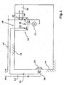
- FIG. 1 shows a wall 10 and a ceiling 11 of a room.
- a power switch 12 which is connected to a designated Ph Phase line 13 of the installed electrical supply network connected is.
- gPh clean lying switched Supply line 14 which is designated gPh (switched phase).
- the switched phase line 14 leads to a ceiling outlet 15 in the ceiling 11. At the ceiling outlet 15 is also a line 16 a neutral N to Provided.
- the supply circuit 20 is installed. At this is the first consumer 21 connected, which is a light is, which is switched by the power switch 12. Furthermore, to the Supply circuit connected to the second consumer 22, which is itself Here is a permanently to be supplied smoke detector 22, the also mounted under the ceiling 11.
- the supply circuit 20 operates independently of the Position of the power switch 12 is a permanent supply of the second Consumer 22, while the first consumer 21 depending on the Position of the power switch 12 is switched and supplied.
- a rectifier 31 in the form of a Doppelweg rectifier provided. This forms together with the first Reactance 30 and a second reactance 32, also in shape of a capacitor, a series circuit 33 between phase Ph and neutral N.
- the first load circuit 34 consists of the series connection of Power switch 12, a yet to be explained further switch 35 and the first consumer 21.
- the first consumer circuit 34 is at phase Ph and Neutral N connected.
- a second load circuit 36 is connected to the output of the rectifier 31 connected.
- the second load circuit 36 includes a current detector 37 from a series resistor 38 and one with the two ends of the Series resistor connected differential amplifier 39.
- the series resistance 38 is a current sense resistor.
- the differential amplifier 39 switches a relay 40, which operates the switch 35. Turning on the power switch is the impedance 30 bridges, and thus the total impedance in the second Consumer circle lower. Then the current in the second exceeds Consumer circuit 36, the threshold of the current detector 37, whereby the relay 40 closes the switch 35. This switch remains closed as long as the Power switch 12 is closed. If the power switch 12 is opened, that falls Relay 40 again and the switch 35 also opens. The switch 35 is So with a slight delay in sync with the respective Switching state of the power switch 12 controlled.
- the second load circuit 36 includes the terminals 26 and 27, to which the second consumer 22 is connected. Parallel to this is a Voltage stabilizing circuit 41 is provided, which i.a. a zener diode contains and a (not shown) smoothing capacitor. In addition, in the second load circuit 36 a (not shown) DC-DC converter be included, which has a DC voltage to a lower or higher value.
- the impedance 30 is bridged and reduces the total impedance in the rectifier circuit. This increases the current in the second load circuit 36.
- the switch 35 is closed, so that the first load 21 now with AC power is supplied.
- the second consumer 22 is as before with DC powered. Therefore, the first consumer 21 is a switched Consumers and the second consumer 22 a permanently supplied Consumer.
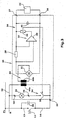
- FIG. 3 shows an exemplary embodiment with galvanic decoupling between the first and the second consumer circuit.
- the rectifier 31 is not more directly in the series circuit 33 of Figure 2 included. Rather, the Reactive impedance 32 replaced by the primary winding 44a of a transformer 44.
- the primary winding 44a of the transformer is included in the series circuit 33 and the secondary winding 44b is connected to the input of the rectifier 31 connected. As a result, the second consumer 22 is kept floating.
- the second consumer 22 may be a radio module for transmitting a Signaling signal included.
Landscapes
- Engineering & Computer Science (AREA)
- Power Engineering (AREA)
- Keying Circuit Devices (AREA)
- Alarm Systems (AREA)
- Fire Alarms (AREA)
- Electronic Switches (AREA)
- Burglar Alarm Systems (AREA)
- Details Of Connecting Devices For Male And Female Coupling (AREA)
- Structure Of Telephone Exchanges (AREA)
- Exchange Systems With Centralized Control (AREA)
- Control Of Electrical Variables (AREA)
Abstract
Description
- Fig. 1
- eine Darstellung der Einbausituation der Versorgungsschaltung in einem Raum,
- Fig. 2
- ein schematisches Schaltbild der Versorgungsschaltung und ihrer Verbindungen mit dem Netzschalter und den beiden Verbrauchern, und
- Fig. 3
- ein weiteres Ausführungsbeispiel der Versorgungsschaltung mit einer Potentialtrennung des zweiten Verbraucherkreises von dem ersten Verbraucherkreis.
Claims (9)
- Versorgungsschaltung zur schaltbaren Versorgung eines ersten Verbrauchers (21) und zur permanenten Versorgung eines zweiten Verbrauchers (22) durch eine mit einem Netzschalter (12) schaltbare zweiadrige Leitung, mit
einem den Netzschalter (12) überbrückenden ersten Blindwiderstand (30), der zusammen mit einem zweiten Blindwiderstand eine an die Netzspannung anschließbare Reihenschaltung zur Speisung eines Gleichrichters bildet,
einem den ersten Verbraucher (21) enthaltenden ersten Verbraucherkreis (34),
einem von dem Gleichrichter (31) versorgten zweiten Verbraucherkreis (36), der den zweiten Verbraucher (22) enthält,
und einem in dem ersten Verbraucherkreis (34) liegenden Schalter (35), der durch das Schließen des Netzschalters (12) geschlossen wird. - Versorgungsschaltung nach Anspruch 1, dadurch gekennzeichnet, dass das Schließen des Schalters (35) durch einen in dem zweiten Verbraucherkreis (36) liegenden Stromdetektor (37) veranlasst wird, wenn der im zweiten Verbraucherkreis fließende Strom infolge der Einschaltung des Netzschalters einen Schwellwert überschreitet.
- Versorgungsschaltung nach Anspruch 1 oder 2, dadurch gekennzeichnet, dass der zweite Verbraucherkreis (36) parallel zu dem zweiten Verbraucher eine Spannungsstabilisierungsschaltung (41) enthält.
- Versorgungsschaltung nach einem der Ansprüche 1 - 3, dadurch gekennzeichnet, dass der zweite Verbraucherkreis (36) einen Gleichspannungswandler enthält, der aus einer höheren Gleichspannung eine niedrigere Verbraucherspannung erzeugt.
- Versorgungsschaltung nach einem der Ansprüche 1 - 4, dadurch gekennzeichnet, dass der zweite Verbraucherkreis (36) einen Gleichspannungswandler enthält, der aus der zur Verfügung stehenden geglätteten Gleichrichterspannung eine höhere Verbraucherspannung erzeugt.
- Versorgungsschaltung nach einem der Ansprüche 1 - 5, dadurch gekennzeichnet, dass die die Blindwiderstände (30,32) enthaltende Reihenschaltung (33) über einen Übertrager (44) zur Potentialtrennung mit dem Gleichrichter (31) verbunden ist.
- Versorgungsschaltung nach einem der Ansprüche 1 - 6, dadurch gekennzeichnet, dass der zweite Verbraucher (22) ein Brandmelder ist.
- Versorgungsschaltung nach einem der Ansprüche 1 - 7, dadurch gekennzeichnet, dass der zweite Verbraucher (22) ein Funkmodul zum Aussenden eines Meldesignals enthält.
- Versorgungsschaltung nach einem der Ansprüche 1 - 8, dadurch gekennzeichnet, dass die beiden Blindwiderstände (30,32) in der Reihenschaltung auf verschiedenen Seiten des Gleichrichters (31) angeordnet sind.
Applications Claiming Priority (2)
| Application Number | Priority Date | Filing Date | Title |
|---|---|---|---|
| DE10353135A DE10353135A1 (de) | 2003-11-14 | 2003-11-14 | Versorgungsschaltung zur permanenten Versorgung eines Verbrauchers über eine schaltbare Leitung |
| DE10353135 | 2003-11-14 |
Publications (2)
| Publication Number | Publication Date |
|---|---|
| EP1531533A1 true EP1531533A1 (de) | 2005-05-18 |
| EP1531533B1 EP1531533B1 (de) | 2007-01-24 |
Family
ID=34428726
Family Applications (1)
| Application Number | Title | Priority Date | Filing Date |
|---|---|---|---|
| EP04026495A Expired - Lifetime EP1531533B1 (de) | 2003-11-14 | 2004-11-09 | Versorgungsschaltung zur permanenten Versorgung eines Verbrauchers über eine schaltbare Leitung |
Country Status (5)
| Country | Link |
|---|---|
| EP (1) | EP1531533B1 (de) |
| AT (1) | ATE352896T1 (de) |
| DE (2) | DE10353135A1 (de) |
| DK (1) | DK1531533T3 (de) |
| ES (1) | ES2281734T3 (de) |
Cited By (3)
| Publication number | Priority date | Publication date | Assignee | Title |
|---|---|---|---|---|
| WO2008118806A1 (en) | 2007-03-23 | 2008-10-02 | Qualcomm Incorporated | Reduction of second-order distortion caused by transmit signal leakage |
| CN102938560A (zh) * | 2012-10-19 | 2013-02-20 | 浙江大学 | 一种基于双极式结构的直流换流站 |
| EP3243195A4 (de) * | 2015-01-06 | 2018-08-22 | Cmoo Systems Itd. | Verfahren und vorrichtung zur energieextraktion bei einer bestehenden wechselstromverdrahtungsinfrastruktur |
Families Citing this family (2)
| Publication number | Priority date | Publication date | Assignee | Title |
|---|---|---|---|---|
| DE102015006237A1 (de) | 2015-04-28 | 2016-11-03 | Peucon GmbH | Vorrichtung zur durchgängigen Versorgung eines Verbrauchers mit elektrischer Energie |
| EP3089318B1 (de) | 2015-04-28 | 2019-08-14 | Peucon GmbH | Vorrichtung zur durchgängigen versorgung eines verbrauchers mit elektrischer ernergie |
Citations (4)
| Publication number | Priority date | Publication date | Assignee | Title |
|---|---|---|---|---|
| DE514564C (de) * | 1926-12-11 | 1930-12-13 | Siemens Schuckertwerke Akt Ges | Vorrichtung zum Anzeigen der Stellung eines zum Schalten von Stromverbrauchern an das Netz dienenden Schalters |
| DE2024092A1 (de) * | 1970-05-16 | 1971-12-02 | Licentia Gmbh | Netzgerät mit Gleichspannungswandler und Regelung auf konstante Ausgangsgleichspannung |
| EP0689351A2 (de) * | 1994-06-23 | 1995-12-27 | NOKIA TECHNOLOGY GmbH | Schaltungsanordnung für den Wartebetrieb eines fernbedienbaren Gerätes |
| EP0911775A2 (de) * | 1997-09-30 | 1999-04-28 | Siemens Aktiengesellschaft | Verfahren zur Funkübertragung in einem Gefahrenmeldesystem |
Family Cites Families (4)
| Publication number | Priority date | Publication date | Assignee | Title |
|---|---|---|---|---|
| EP1202232A3 (de) * | 1995-04-20 | 2003-11-05 | The Nippon Signal Co. Ltd. | Überwachungseinrichtung und Steuereinrichtung für Signallampen |
| DE19534564C2 (de) * | 1995-09-18 | 1998-12-24 | Andreas Toeteberg | Verfahren zur Informationsweitergabe zwischen Alarmgeräten oder anderen Systemgeräten eines Alarmsystems |
| DE20103244U1 (de) * | 2001-02-23 | 2001-06-07 | SYKO Reinhard Kalfhaus, 63533 Mainhausen | Spannungsversorgungssystem |
| DE20116719U1 (de) * | 2001-10-11 | 2001-12-20 | Busse, Heiko, 33442 Herzebrock-Clarholz | Nachtlichtschaltung mit Hochleistungs-LEDs |
-
2003
- 2003-11-14 DE DE10353135A patent/DE10353135A1/de not_active Withdrawn
-
2004
- 2004-11-09 EP EP04026495A patent/EP1531533B1/de not_active Expired - Lifetime
- 2004-11-09 ES ES04026495T patent/ES2281734T3/es not_active Expired - Lifetime
- 2004-11-09 AT AT04026495T patent/ATE352896T1/de active
- 2004-11-09 DK DK04026495T patent/DK1531533T3/da active
- 2004-11-09 DE DE502004002753T patent/DE502004002753D1/de not_active Expired - Lifetime
Patent Citations (4)
| Publication number | Priority date | Publication date | Assignee | Title |
|---|---|---|---|---|
| DE514564C (de) * | 1926-12-11 | 1930-12-13 | Siemens Schuckertwerke Akt Ges | Vorrichtung zum Anzeigen der Stellung eines zum Schalten von Stromverbrauchern an das Netz dienenden Schalters |
| DE2024092A1 (de) * | 1970-05-16 | 1971-12-02 | Licentia Gmbh | Netzgerät mit Gleichspannungswandler und Regelung auf konstante Ausgangsgleichspannung |
| EP0689351A2 (de) * | 1994-06-23 | 1995-12-27 | NOKIA TECHNOLOGY GmbH | Schaltungsanordnung für den Wartebetrieb eines fernbedienbaren Gerätes |
| EP0911775A2 (de) * | 1997-09-30 | 1999-04-28 | Siemens Aktiengesellschaft | Verfahren zur Funkübertragung in einem Gefahrenmeldesystem |
Cited By (4)
| Publication number | Priority date | Publication date | Assignee | Title |
|---|---|---|---|---|
| WO2008118806A1 (en) | 2007-03-23 | 2008-10-02 | Qualcomm Incorporated | Reduction of second-order distortion caused by transmit signal leakage |
| CN102938560A (zh) * | 2012-10-19 | 2013-02-20 | 浙江大学 | 一种基于双极式结构的直流换流站 |
| EP3243195A4 (de) * | 2015-01-06 | 2018-08-22 | Cmoo Systems Itd. | Verfahren und vorrichtung zur energieextraktion bei einer bestehenden wechselstromverdrahtungsinfrastruktur |
| US10448586B2 (en) | 2015-01-06 | 2019-10-22 | Cmoo Systems Ltd. | Method and apparatus for power extraction in a pre-existing AC wiring infrastructure |
Also Published As
| Publication number | Publication date |
|---|---|
| ATE352896T1 (de) | 2007-02-15 |
| DE502004002753D1 (de) | 2007-03-15 |
| DE10353135A1 (de) | 2005-06-09 |
| EP1531533B1 (de) | 2007-01-24 |
| DK1531533T3 (da) | 2007-05-21 |
| ES2281734T3 (es) | 2007-10-01 |
Similar Documents
| Publication | Publication Date | Title |
|---|---|---|
| DE69424583T2 (de) | Zweistufiges Beleuchtungssteuerungssystem für Starkstromentladungslampen | |
| EP2280493B1 (de) | Sicherheitsbezogenes Kommunikationsverfahren auf Energieversorgungsleitungen und ein dazugehöriges Netz | |
| DE102009022874B4 (de) | Sicherheitsbeleuchtungsanlage mit spezieller Endstromkreistopologie und endstromkreisbildende Schalteinheiten | |
| DE3750222T2 (de) | Leistungsversorgung, verbunden mit dem relais einer wechselstromleitung. | |
| DE69831666T2 (de) | Niederspannungsbeleuchtungssystem | |
| DE4311096C1 (de) | Teilnehmereinrichtung für ein Installationsbussystem | |
| EP1531533B1 (de) | Versorgungsschaltung zur permanenten Versorgung eines Verbrauchers über eine schaltbare Leitung | |
| DE202015104940U1 (de) | Anschlussklemme mit Bus-Ausgangsanschluss zur Bereitstellung einer DC-Busspannung für wenigstens ein Betriebsgerät | |
| EP0437696A1 (de) | Fernschalt- oder fernsteuerbare Anschlussvorrichtung | |
| DE2952584C2 (de) | ||
| DE102020107397A1 (de) | Modulares Lichtsystem | |
| DE102019106484A1 (de) | Gleichrichteranordnung | |
| DE2952583A1 (de) | Isolatorschaltung | |
| EP1470741B1 (de) | Steuereinrichtung für den betrieb einer mehrzahl von leuchten | |
| DE102022111694B4 (de) | Schaltungsanordnung zur getakteten Stromversorgung eines elektrischen Zusatzgerätes am Ort eines geschalteten elektrischen Verbrauchers und Gebäudedatenverarbeitungsgerät, Sockelmodul und Treppenhausinstallation | |
| DE60307034T2 (de) | Schaltungsanordnung zur Steuerung eines Triacs ohne galvanische Trennung | |
| AT409193B (de) | Schaltungsanordnung | |
| DE102018130072A1 (de) | Verfahren und anordnung zum vermeiden von ungewolltem glimmen von leds | |
| DE29720980U1 (de) | Elektronischer Installationsfernschalter | |
| DE2753314C2 (de) | Elektrische Schaltung zum kontaktlosen Schalten elektrischer Verbraucher | |
| AT386704B (de) | Anordnung zur stromversorgung | |
| DE2607722C2 (en) | Overvoltage protection system for TV aerial system - has AC receiver, transformer switches and overvoltage triggers | |
| DE19650695C1 (de) | Netzgerät für eine elektrische Türanlage | |
| DE3200973A1 (de) | Elektronische klangverteilungsanlage | |
| DE202010017741U1 (de) | Schaltungsanordnung mit einem elektronischen Vorschaltgerät und einer Entladungslampe sowie Vorschaltgerät |
Legal Events
| Date | Code | Title | Description |
|---|---|---|---|
| PUAI | Public reference made under article 153(3) epc to a published international application that has entered the european phase |
Free format text: ORIGINAL CODE: 0009012 |
|
| AK | Designated contracting states |
Kind code of ref document: A1 Designated state(s): AT BE BG CH CY CZ DE DK EE ES FI FR GB GR HU IE IS IT LI LU MC NL PL PT RO SE SI SK TR |
|
| AX | Request for extension of the european patent |
Extension state: AL HR LT LV MK YU |
|
| 17P | Request for examination filed |
Effective date: 20050622 |
|
| AKX | Designation fees paid |
Designated state(s): AT BE BG CH CY CZ DE DK EE ES FI FR GB GR HU IE IS IT LI LU MC NL PL PT RO SE SI SK TR |
|
| GRAP | Despatch of communication of intention to grant a patent |
Free format text: ORIGINAL CODE: EPIDOSNIGR1 |
|
| GRAS | Grant fee paid |
Free format text: ORIGINAL CODE: EPIDOSNIGR3 |
|
| GRAA | (expected) grant |
Free format text: ORIGINAL CODE: 0009210 |
|
| AK | Designated contracting states |
Kind code of ref document: B1 Designated state(s): AT BE BG CH CY CZ DE DK EE ES FI FR GB GR HU IE IS IT LI LU MC NL PL PT RO SE SI SK TR |
|
| PG25 | Lapsed in a contracting state [announced via postgrant information from national office to epo] |
Ref country code: IE Free format text: LAPSE BECAUSE OF FAILURE TO SUBMIT A TRANSLATION OF THE DESCRIPTION OR TO PAY THE FEE WITHIN THE PRESCRIBED TIME-LIMIT Effective date: 20070124 Ref country code: SI Free format text: LAPSE BECAUSE OF FAILURE TO SUBMIT A TRANSLATION OF THE DESCRIPTION OR TO PAY THE FEE WITHIN THE PRESCRIBED TIME-LIMIT Effective date: 20070124 Ref country code: PL Free format text: LAPSE BECAUSE OF FAILURE TO SUBMIT A TRANSLATION OF THE DESCRIPTION OR TO PAY THE FEE WITHIN THE PRESCRIBED TIME-LIMIT Effective date: 20070124 |
|
| REG | Reference to a national code |
Ref country code: GB Ref legal event code: FG4D Free format text: NOT ENGLISH |
|
| REG | Reference to a national code |
Ref country code: CH Ref legal event code: NV Representative=s name: ISLER & PEDRAZZINI AG Ref country code: CH Ref legal event code: EP |
|
| REG | Reference to a national code |
Ref country code: IE Ref legal event code: FG4D Free format text: LANGUAGE OF EP DOCUMENT: GERMAN |
|
| REF | Corresponds to: |
Ref document number: 502004002753 Country of ref document: DE Date of ref document: 20070315 Kind code of ref document: P |
|
| PG25 | Lapsed in a contracting state [announced via postgrant information from national office to epo] |
Ref country code: BG Free format text: LAPSE BECAUSE OF FAILURE TO SUBMIT A TRANSLATION OF THE DESCRIPTION OR TO PAY THE FEE WITHIN THE PRESCRIBED TIME-LIMIT Effective date: 20070425 |
|
| REG | Reference to a national code |
Ref country code: SE Ref legal event code: TRGR |
|
| REG | Reference to a national code |
Ref country code: DK Ref legal event code: T3 |
|
| GBT | Gb: translation of ep patent filed (gb section 77(6)(a)/1977) |
Effective date: 20070427 |
|
| PG25 | Lapsed in a contracting state [announced via postgrant information from national office to epo] |
Ref country code: IS Free format text: LAPSE BECAUSE OF FAILURE TO SUBMIT A TRANSLATION OF THE DESCRIPTION OR TO PAY THE FEE WITHIN THE PRESCRIBED TIME-LIMIT Effective date: 20070524 |
|
| PG25 | Lapsed in a contracting state [announced via postgrant information from national office to epo] |
Ref country code: PT Free format text: LAPSE BECAUSE OF FAILURE TO SUBMIT A TRANSLATION OF THE DESCRIPTION OR TO PAY THE FEE WITHIN THE PRESCRIBED TIME-LIMIT Effective date: 20070625 |
|
| ET | Fr: translation filed | ||
| REG | Reference to a national code |
Ref country code: IE Ref legal event code: FD4D |
|
| REG | Reference to a national code |
Ref country code: CH Ref legal event code: PCAR Free format text: ISLER & PEDRAZZINI AG;POSTFACH 1772;8027 ZUERICH (CH) |
|
| REG | Reference to a national code |
Ref country code: ES Ref legal event code: FG2A Ref document number: 2281734 Country of ref document: ES Kind code of ref document: T3 |
|
| PG25 | Lapsed in a contracting state [announced via postgrant information from national office to epo] |
Ref country code: SK Free format text: LAPSE BECAUSE OF FAILURE TO SUBMIT A TRANSLATION OF THE DESCRIPTION OR TO PAY THE FEE WITHIN THE PRESCRIBED TIME-LIMIT Effective date: 20070124 |
|
| PLBE | No opposition filed within time limit |
Free format text: ORIGINAL CODE: 0009261 |
|
| STAA | Information on the status of an ep patent application or granted ep patent |
Free format text: STATUS: NO OPPOSITION FILED WITHIN TIME LIMIT |
|
| 26N | No opposition filed |
Effective date: 20071025 |
|
| PG25 | Lapsed in a contracting state [announced via postgrant information from national office to epo] |
Ref country code: CZ Free format text: LAPSE BECAUSE OF FAILURE TO SUBMIT A TRANSLATION OF THE DESCRIPTION OR TO PAY THE FEE WITHIN THE PRESCRIBED TIME-LIMIT Effective date: 20070124 Ref country code: RO Free format text: LAPSE BECAUSE OF FAILURE TO SUBMIT A TRANSLATION OF THE DESCRIPTION OR TO PAY THE FEE WITHIN THE PRESCRIBED TIME-LIMIT Effective date: 20070124 |
|
| PG25 | Lapsed in a contracting state [announced via postgrant information from national office to epo] |
Ref country code: GR Free format text: LAPSE BECAUSE OF FAILURE TO SUBMIT A TRANSLATION OF THE DESCRIPTION OR TO PAY THE FEE WITHIN THE PRESCRIBED TIME-LIMIT Effective date: 20070425 |
|
| PG25 | Lapsed in a contracting state [announced via postgrant information from national office to epo] |
Ref country code: MC Free format text: LAPSE BECAUSE OF NON-PAYMENT OF DUE FEES Effective date: 20071130 |
|
| REG | Reference to a national code |
Ref country code: DK Ref legal event code: EBP |
|
| PG25 | Lapsed in a contracting state [announced via postgrant information from national office to epo] |
Ref country code: FI Free format text: LAPSE BECAUSE OF NON-PAYMENT OF DUE FEES Effective date: 20071109 |
|
| PG25 | Lapsed in a contracting state [announced via postgrant information from national office to epo] |
Ref country code: DK Free format text: LAPSE BECAUSE OF NON-PAYMENT OF DUE FEES Effective date: 20071130 |
|
| PG25 | Lapsed in a contracting state [announced via postgrant information from national office to epo] |
Ref country code: EE Free format text: LAPSE BECAUSE OF FAILURE TO SUBMIT A TRANSLATION OF THE DESCRIPTION OR TO PAY THE FEE WITHIN THE PRESCRIBED TIME-LIMIT Effective date: 20070124 |
|
| PG25 | Lapsed in a contracting state [announced via postgrant information from national office to epo] |
Ref country code: CY Free format text: LAPSE BECAUSE OF FAILURE TO SUBMIT A TRANSLATION OF THE DESCRIPTION OR TO PAY THE FEE WITHIN THE PRESCRIBED TIME-LIMIT Effective date: 20070124 |
|
| PG25 | Lapsed in a contracting state [announced via postgrant information from national office to epo] |
Ref country code: LU Free format text: LAPSE BECAUSE OF NON-PAYMENT OF DUE FEES Effective date: 20071109 |
|
| PG25 | Lapsed in a contracting state [announced via postgrant information from national office to epo] |
Ref country code: TR Free format text: LAPSE BECAUSE OF FAILURE TO SUBMIT A TRANSLATION OF THE DESCRIPTION OR TO PAY THE FEE WITHIN THE PRESCRIBED TIME-LIMIT Effective date: 20070124 Ref country code: HU Free format text: LAPSE BECAUSE OF FAILURE TO SUBMIT A TRANSLATION OF THE DESCRIPTION OR TO PAY THE FEE WITHIN THE PRESCRIBED TIME-LIMIT Effective date: 20070725 |
|
| REG | Reference to a national code |
Ref country code: FR Ref legal event code: PLFP Year of fee payment: 12 |
|
| REG | Reference to a national code |
Ref country code: FR Ref legal event code: PLFP Year of fee payment: 13 |
|
| PGFP | Annual fee paid to national office [announced via postgrant information from national office to epo] |
Ref country code: IT Payment date: 20161122 Year of fee payment: 13 |
|
| REG | Reference to a national code |
Ref country code: FR Ref legal event code: PLFP Year of fee payment: 14 |
|
| PGFP | Annual fee paid to national office [announced via postgrant information from national office to epo] |
Ref country code: GB Payment date: 20171108 Year of fee payment: 14 |
|
| REG | Reference to a national code |
Ref country code: FR Ref legal event code: PLFP Year of fee payment: 15 |
|
| PG25 | Lapsed in a contracting state [announced via postgrant information from national office to epo] |
Ref country code: IT Free format text: LAPSE BECAUSE OF NON-PAYMENT OF DUE FEES Effective date: 20171109 |
|
| GBPC | Gb: european patent ceased through non-payment of renewal fee |
Effective date: 20181109 |
|
| PG25 | Lapsed in a contracting state [announced via postgrant information from national office to epo] |
Ref country code: GB Free format text: LAPSE BECAUSE OF NON-PAYMENT OF DUE FEES Effective date: 20181109 |
|
| PGFP | Annual fee paid to national office [announced via postgrant information from national office to epo] |
Ref country code: NL Payment date: 20231013 Year of fee payment: 20 Ref country code: FR Payment date: 20230929 Year of fee payment: 20 |
|
| PGFP | Annual fee paid to national office [announced via postgrant information from national office to epo] |
Ref country code: ES Payment date: 20231208 Year of fee payment: 20 |
|
| PGFP | Annual fee paid to national office [announced via postgrant information from national office to epo] |
Ref country code: SE Payment date: 20231002 Year of fee payment: 20 Ref country code: DE Payment date: 20230929 Year of fee payment: 20 Ref country code: AT Payment date: 20231025 Year of fee payment: 20 |
|
| PGFP | Annual fee paid to national office [announced via postgrant information from national office to epo] |
Ref country code: BE Payment date: 20231016 Year of fee payment: 20 |
|
| PGFP | Annual fee paid to national office [announced via postgrant information from national office to epo] |
Ref country code: CH Payment date: 20240127 Year of fee payment: 20 |
|
| REG | Reference to a national code |
Ref country code: DE Ref legal event code: R071 Ref document number: 502004002753 Country of ref document: DE |
|
| REG | Reference to a national code |
Ref country code: NL Ref legal event code: MK Effective date: 20241108 |
|
| REG | Reference to a national code |
Ref country code: CH Ref legal event code: PL |
|
| REG | Reference to a national code |
Ref country code: ES Ref legal event code: FD2A Effective date: 20241127 |
|
| REG | Reference to a national code |
Ref country code: AT Ref legal event code: MK07 Ref document number: 352896 Country of ref document: AT Kind code of ref document: T Effective date: 20241109 |
|
| REG | Reference to a national code |
Ref country code: BE Ref legal event code: MK Effective date: 20241109 |
|
| REG | Reference to a national code |
Ref country code: SE Ref legal event code: EUG |
|
| PG25 | Lapsed in a contracting state [announced via postgrant information from national office to epo] |
Ref country code: ES Free format text: LAPSE BECAUSE OF EXPIRATION OF PROTECTION Effective date: 20241110 |
|
| PG25 | Lapsed in a contracting state [announced via postgrant information from national office to epo] |
Ref country code: ES Free format text: LAPSE BECAUSE OF EXPIRATION OF PROTECTION Effective date: 20241110 |