EP1531325A1 - Verfahren und Vorrichtung zum Entnehmen von gasförmigen Bestandteilen aus einem Gasstrom insbesondere aus verdünnten Abgasen von einer Brennkraftmaschine - Google Patents
Verfahren und Vorrichtung zum Entnehmen von gasförmigen Bestandteilen aus einem Gasstrom insbesondere aus verdünnten Abgasen von einer Brennkraftmaschine Download PDFInfo
- Publication number
- EP1531325A1 EP1531325A1 EP04292506A EP04292506A EP1531325A1 EP 1531325 A1 EP1531325 A1 EP 1531325A1 EP 04292506 A EP04292506 A EP 04292506A EP 04292506 A EP04292506 A EP 04292506A EP 1531325 A1 EP1531325 A1 EP 1531325A1
- Authority
- EP
- European Patent Office
- Prior art keywords
- sampling
- gaseous
- adsorbent
- dilution air
- passage
- Prior art date
- Legal status (The legal status is an assumption and is not a legal conclusion. Google has not performed a legal analysis and makes no representation as to the accuracy of the status listed.)
- Withdrawn
Links
- 238000005070 sampling Methods 0.000 title claims abstract description 101
- 238000000034 method Methods 0.000 title claims abstract description 21
- 238000002485 combustion reaction Methods 0.000 title claims abstract description 13
- 239000007789 gas Substances 0.000 title description 66
- 125000005575 polycyclic aromatic hydrocarbon group Chemical group 0.000 claims abstract description 47
- 239000003463 adsorbent Substances 0.000 claims abstract description 28
- 150000001875 compounds Chemical class 0.000 claims abstract description 6
- 238000010790 dilution Methods 0.000 claims description 38
- 239000012895 dilution Substances 0.000 claims description 38
- 238000001914 filtration Methods 0.000 claims description 26
- 230000008569 process Effects 0.000 claims description 13
- 229920005989 resin Polymers 0.000 claims description 9
- 239000011347 resin Substances 0.000 claims description 9
- 229920000642 polymer Polymers 0.000 claims description 5
- CHRJZRDFSQHIFI-UHFFFAOYSA-N 1,2-bis(ethenyl)benzene;styrene Chemical compound C=CC1=CC=CC=C1.C=CC1=CC=CC=C1C=C CHRJZRDFSQHIFI-UHFFFAOYSA-N 0.000 claims description 3
- 239000011159 matrix material Substances 0.000 claims description 3
- 230000003213 activating effect Effects 0.000 claims description 2
- 238000002156 mixing Methods 0.000 claims description 2
- 230000002000 scavenging effect Effects 0.000 claims 1
- 239000003570 air Substances 0.000 description 30
- 239000012535 impurity Substances 0.000 description 5
- 238000000605 extraction Methods 0.000 description 4
- YMWUJEATGCHHMB-UHFFFAOYSA-N Dichloromethane Chemical compound ClCCl YMWUJEATGCHHMB-UHFFFAOYSA-N 0.000 description 3
- YXFVVABEGXRONW-UHFFFAOYSA-N Toluene Chemical compound CC1=CC=CC=C1 YXFVVABEGXRONW-UHFFFAOYSA-N 0.000 description 3
- 238000004891 communication Methods 0.000 description 3
- 238000007599 discharging Methods 0.000 description 3
- 229930195733 hydrocarbon Natural products 0.000 description 3
- 150000002430 hydrocarbons Chemical class 0.000 description 3
- 230000009471 action Effects 0.000 description 2
- 238000004458 analytical method Methods 0.000 description 2
- 230000008901 benefit Effects 0.000 description 2
- 238000004587 chromatography analysis Methods 0.000 description 2
- 239000002245 particle Substances 0.000 description 2
- 238000000899 pressurised-fluid extraction Methods 0.000 description 2
- 238000011002 quantification Methods 0.000 description 2
- 230000000717 retained effect Effects 0.000 description 2
- 239000002904 solvent Substances 0.000 description 2
- 239000004215 Carbon black (E152) Substances 0.000 description 1
- 239000012494 Quartz wool Substances 0.000 description 1
- 239000004809 Teflon Substances 0.000 description 1
- 229920006362 Teflon® Polymers 0.000 description 1
- 239000002250 absorbent Substances 0.000 description 1
- 230000002745 absorbent Effects 0.000 description 1
- 230000006978 adaptation Effects 0.000 description 1
- 239000012080 ambient air Substances 0.000 description 1
- 238000012512 characterization method Methods 0.000 description 1
- 229920001429 chelating resin Polymers 0.000 description 1
- 239000000470 constituent Substances 0.000 description 1
- 238000011109 contamination Methods 0.000 description 1
- 230000008878 coupling Effects 0.000 description 1
- 238000010168 coupling process Methods 0.000 description 1
- 238000005859 coupling reaction Methods 0.000 description 1
- 239000000428 dust Substances 0.000 description 1
- 230000036541 health Effects 0.000 description 1
- 238000004128 high performance liquid chromatography Methods 0.000 description 1
- 230000007257 malfunction Effects 0.000 description 1
- 210000000056 organ Anatomy 0.000 description 1
- 239000003960 organic solvent Substances 0.000 description 1
- 125000003367 polycyclic group Chemical group 0.000 description 1
- 238000004611 spectroscopical analysis Methods 0.000 description 1
- 238000012360 testing method Methods 0.000 description 1
- 231100001234 toxic pollutant Toxicity 0.000 description 1
- 238000012546 transfer Methods 0.000 description 1
- 230000000007 visual effect Effects 0.000 description 1
- XLYOFNOQVPJJNP-UHFFFAOYSA-N water Substances O XLYOFNOQVPJJNP-UHFFFAOYSA-N 0.000 description 1
Images

Classifications
-
- G—PHYSICS
- G01—MEASURING; TESTING
- G01N—INVESTIGATING OR ANALYSING MATERIALS BY DETERMINING THEIR CHEMICAL OR PHYSICAL PROPERTIES
- G01N1/00—Sampling; Preparing specimens for investigation
- G01N1/02—Devices for withdrawing samples
- G01N1/22—Devices for withdrawing samples in the gaseous state
- G01N1/2202—Devices for withdrawing samples in the gaseous state involving separation of sample components during sampling
- G01N1/2214—Devices for withdrawing samples in the gaseous state involving separation of sample components during sampling by sorption
Definitions
- the present invention relates to a method and a device for sampling gaseous compounds contained in a gas stream, especially polycyclic aromatic hydrocarbons contained in diluted exhaust gas from an engine, in particular an internal combustion engine. More particularly, it is directed to a method and a sampling device from internal combustion engines of test cells, roller bench or motor bench.
- PAHs Polycyclic Aromatic Hydrocarbons
- PAHs are considered as toxic pollutants for human health and all means are sought to identify, quantify and treat them if necessary.
- PAHs are present, in particular in engine exhaust gases, in gaseous form for PAHs whose molecular structure is less than four cycles or in condensed form on the particulate phase of these gases for PAHs with a molecular structure greater than four cycles.
- PAHs present on the particulate phase are almost nonexistent in the exhaust and the majority of PAHs are in gaseous form. In this case, the sample taken is not representative of PAH present in the exhaust.
- PAHs in gaseous form present in the exhaust gas through a trapping of hydrocarbons beyond C14. From these hydrocarbons entrapped PAHs in gaseous form are extracted according to long protocols, then identified and quantified by complex analysis tools. These different operations may involve significant risks of loss or contamination of PAHs.
- the present invention proposes to overcome the disadvantages mentioned above through a sampling method and device simple and effective way of collecting PAHs in gaseous form and quantify them using commonly used extraction and analysis equipment used.
- the present invention relates to a method for gaseous compounds contained in a gaseous stream, especially in gases exhaust system of an internal combustion engine, characterized in that consists of making a passage of the gas stream in at least one channel of sample containing an adsorbent trapping aromatic hydrocarbons polycyclic in gaseous form.
- this process can consist in carrying out a filtration of gas stream before passing through the adsorbent.
- It may consist of making a passage of the gas stream in a first sampling path, to interrupt the passage of the gas stream in the first sampling path and to make a passage of the current gaseous in a second sampling path.
- the process may consist in carrying out a passage of the dilution air in at least one sampling path containing an adsorbent trapping the polycyclic aromatic hydrocarbons in gaseous form.
- It may also consist in making a passage of the dilution air in a first sampling path, to interrupt the passage of the dilution air in said first sampling channel and to make a passage of this air in a second sampling path.
- it may consist in filtering the dilution air before its passage through the adsorbent.
- An adsorbent containing a polymer-based resin can be used porous.
- This resin may be a resin with a matrix of type polyaromatic styrene / divinylbenzene.
- the invention also relates to a device for sampling compounds gases contained in a gaseous stream, especially in gases exhaust system of an internal combustion engine, characterized in that includes a sampling unit provided with at least one sampling comprising at least one sampling means containing a adsorbent trapping polycyclic aromatic hydrocarbons in form gas contained in said stream.
- the sampling circuit may comprise an air filtration means of dilution before mixing with the gas stream, when said stream gas contains such a dilution air.
- the sampling circuit may comprise at least one means of sample containing an adsorbent trapping aromatic hydrocarbons polycyclic gaseous form contained in said dilution air.
- the sampling means may comprise at least one cartridge containing the adsorbent.
- the adsorbent may comprise a resin based on porous polymers.
- the sampling circuit may comprise a filtration means of gaseous current.
- the sampling unit may comprise two sampling circuits and winnowing means for activating one or the other of the circuits of sample.
- the device may include a control unit of the sample.
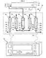
- the Hydrocarbon sampling device Polycyclic Aromatics (PAHs) in gaseous form contained in a gaseous current, such as diluted engine exhaust internal combustion placed on a dynamometer, includes a unit of sampling 10 and a control unit 12 of the unit 10.
- This sampling device is associated with a sampling tunnel 14, which, in the "roller bank” configuration, is a full dilution tunnel flow, in which the exhaust gases 16 flow from the engine to internal combustion.
- This tunnel is supplied with dilution air, generally from the ambient air treated by a pipe 18 so as to obtain at the level of the head 20 located near the exit of this tunnel, gases diluted exhaust systems meeting the usual sampling criteria (temperature, water content, ).
- the sampling unit 10 comprises at least one sampling circuit 22 PAHs in gaseous form, here two, each having two channels of sampling, a channel 24 to take the PAHs contained in the dilution air and a route 26 for PAHs contained in the diluted exhaust gas as well as a filtration path 28 of the dilution air.
- the sampling path 24 of the PAHs contained in the dilution air comprises a capture unit 30 comprising a support 32 in which is placed a removable sampling cartridge 34.
- the cartridge 34 is crossed by dilution air previously filtered by the filtration path 28 and brought by a pipe 36.
- a pipe 38 makes it possible to evacuate the dilution air after capturing the PAHs to all known devices.
- the filtration path 28 comprises a filtration unit 40 with at least at least one filter 42 provided to capture all the impurities contained in the dilution air which passes through this filter.
- the inlet of the filtration unit 40 is connected via a line 44 to the dilution air line 18 and the outlet of this unit is connected by an outlet line 46 to the line 36 leading to the inlet of the unit. capturing unit 30.
- the sampling path 26 of the PAHs contained in the diluted exhaust gases taken by the head 20 comprises a capture unit 48 with a support 50 in which is placed a removable sampling cartridge 52.
- the inlet of the capture unit 48 is connected by a line 54 to the sampling head 20 diluted gases and the output of this unit is connected by a pipe 56 to any known means for discharging and treating the exhaust gas.
- the exhaust gas flowing in the pipe 54 is already filtered, advantageously downstream of the head 20, which makes it possible to eliminate impurities which could clog the sampling cartridge 50.
- the supports 32, 50 and the cartridges 34, 52 may be identical for the two sampling channels.
- the sampling unit 10 comprises a second sampling circuit 22a PAH in gaseous form comprising two sampling channels 24a, 26a with the same components as those described with circuit 22.
- the same filtration path 28 is used for the circuit 22a.
- a valve means 58 is provided, such as a valve three channels, on the outlet pipe 46 of the filtration unit 40 which allows alternatively connect either the pipe 36 or the pipe 36a.
- lines 56 and 56a will each be provided with a means of valve 60 and 60a, such as a rotary type two-way valve or the like, permitting or interrupting the supply of exhaust gas diluted in the capture units 48 and 48a.
- the valves 60 and 60a are ordered in such a way that they are never simultaneously opening or closing position.
- the pipe 36 is in communication with the pipe 46 by action of the valve 58, the valve 60 is in the open position to admit the exhaust gas in the sampling path 26 and the valve 60a is in closing position to prohibit the circulation of these gases in the way of levy 26a.
- the control / control unit 12 makes it possible, in a manner known per se, to parameterize, monitor and / or control continuously the sampling conditions, such as the flow rate, the pressure and the temperature of the exhaust gases and / or dilution air admitted to the inlet of the capture units, the duration of sampling, the actuation of the other sampling circuit 22a in the case of a sampling unit with two circuits per action on the means of winnowing 58, 60 and 60a.
- This unit also controls all the organs related to the operation of this sampling unit, such as pumps allowing the circulation of the gas stream in the filtration channels 26, 28 and sampling 24 of the dilution air. It also includes audible and / or visual alarms to detect any malfunction or failure to comply with a programmed parameter.
- the valve 60 is in the open position, the valve 58 is actuated so as to put in communication the outlet pipe 46 of the filtration channel 28 with the inlet pipe 36 of the sampling path 24 and the valve 60a is in the closed position.
- the exhaust gases 16 from the internal combustion engine of this vehicle are mixed in the tunnel 14 with dilution air supplied by the pipe 18. Part of this dilution air is sent before its introduction into the tunnel 14, through the pipe 44 in the filter unit 28 so as to rid it of impurities it contains, such as dust.
- This filtered dilution air is then sent to the uptake unit 30 of the gaseous HAP and passes through the sampling cartridge 34.
- the gaseous PAHs are captured by the adsorbent contained in this cartridge and the dilution air without to a large extent PAHs are evacuated at the outlet of the unit 30 through line 38 to all known means.
- the diluted exhaust gas previously filtered, are taken near the exit of this tunnel 14 by the head 20 and are sent via line 54 into the capture unit 48 of the PAHs in gaseous form. These gases pass through the cartridge 52 and the gaseous PAHs present in these gases are retained by the adsorbent contained in this cartridge.
- the exhaust gases removed PAH are then removed via line 56 to all known means for their treatment before discharge into the atmosphere.
- the PAHs contained in both the dilution air and the diluted exhaust gas are removed by two cartridges arranged in parallel.
- cartridges 34, 52 disassembled from their supports 32, 50. These cartridges are then treated to extract PAHs from a solvent, such as dichloromethane or toluene.
- a solvent such as dichloromethane or toluene.
- this extraction is carried out using a system accelerated solvent extraction (ASE) which has the advantage of using a very small amount of solvent, which avoids a reconcentration of the adsorbent.
- ASE system accelerated solvent extraction
- the extraction system is adapted to the configuration of the cartridges so as to avoid any dismantling of their constituent elements or any transfer of the adsorbent they contain.
- the extracted PAHs for each cartridge are analyzed by any means, in particular by the coupling of a chromatography with a spectrometry of mass or by high performance liquid chromatography, so that identify and quantify PAHs in dilution air and gases diluted exhaust.
- this sampling device will be associated with all known devices for taking, identifying and quantifying PAHs condensed on the particulate form of the exhaust gas.
- the present invention makes it possible to complete the knowledge of condensed PAHs on the particulate phase contained in the exhaust gases by the identification and quantification of PAHs in gaseous form.
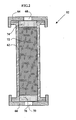
- FIG. 2 shows an exemplary embodiment of the cartridge of sampling 52 which is used in the capture unit 48 of the PAHs contained in the exhaust.
- this same type of cartridge can be used in the unit for capturing PAHs from the dilution air as well as than in the capture units 30a and 48a.
- these types of cartridge allow a fast, simple adaptation without manipulation of the absorbent by the extraction system implemented.
- This cartridge 52 comprises a substantially cylindrical tubular body 62 closed at its ends by two removable covers 64, 66. Each cover is provided with a bore 68, 70 for communicating the interior of the body 62 with respectively the arrival of exhaust gas through the pipe 54 and the evacuation of these gases through the pipe 56.
- the covers are fixed to seal on the body 62 by any known means, such as by screwing.
- the body contains in its hollow volume an adsorbent 72 made of resin based on porous polymers, better known under the name of Amberlite.
- the adsorbent is of the type sold under the name XAD2 Supelpak and comprises a resin with a polyaromatic styrene / divinylbenzene type matrix.
- a bed of quartz wool 74, 76 is disposed between each cover 64, 66 and the adsorbent 72 so as to immobilize this adsorbent inside the body 62 while not penalizing the circulation of the exhaust gases through these beds.
- the bores 68, 70 are configured in such a way that they can be closed by any known means, such as O-ring plugs, after dismounting the cartridge from its support.
- the sampling unit 10 also comprises two sampling circuits 22 and 22a and is associated with a microtunnel 14 which contains a dilution air which is already purified and filtered.
- Each sampling circuit comprises an exhaust gas filtration path 78 connected to a sampling channel 80 of the gaseous HAPs contained in the filtered exhaust gas.
- the filtration path 78 comprises a filtration unit 40 similar to that described above with at least one filter 42 provided for capturing all the impurities contained in the diluted exhaust gas passing through this filter, an inlet pipe 82 for the exhaust gases. exhaust leading these gases from the head 20 to the inlet of the unit 40 and an outlet pipe 84 filtered exhaust gas.
- the inlet pipe carries a valve means 86, in the form of a valve, permitting or prohibiting the arrival of the diluted exhaust gas in this filtration unit 40.
- the sampling path 80 also comprises a capture unit 48, similar to the capture unit of FIG. 1, with a support 50 carrying a removable sampling cartridge 52.
- the input of the capture unit 48 is connected to the outlet pipe 84 of the filtered gases and the outlet of this unit is connected to a pipe 88 for discharging the diluted exhaust gas free of PAH.
- the pipe 84 may comprise a bypass line 90 for discharging a portion of the diluted exhaust gas and filtered, in particular to the microtunnel control system (not shown).
- a valve means 92 such as a three-way valve, for selectively communicating the pipe 90 or the pipe 90a with the microtunnel control system.
- the valve 86 is in the open position so as to put in communication, thanks to the pipe 82, the gases taken by the head 20 with the filtration unit 40 and the valve 92 is in a position such that the pipe 90 allows to evacuate a portion of the exhaust gas after filtration. These diluted gases pass through the filtration unit 40 so as to be rid of the impurities they contain. These filtered exhaust gases are then sent to the capture unit 48 of the gaseous HAPs via the line 84 having previously passed through the sampling cartridge 52 and also into the line 90.
- the gaseous HAPs are collected by the adsorbent contained in this cartridge and the exhaust gases free of PAH are removed via line 88 to all known means.
- the valve 86 is actuated to allow the circulation of the filtered gases in the pipe 90a and the valve 86a can be opened to allow the circulation of the diluted exhaust gas in the filtration channel 78a as well as in the sampling channel 80a.
- this sampling device will be associated with all devices known to collect, identify and quantify the PAH present under condensed form in the particulate phase of these gases.
Landscapes
- Health & Medical Sciences (AREA)
- Life Sciences & Earth Sciences (AREA)
- Engineering & Computer Science (AREA)
- Biomedical Technology (AREA)
- Molecular Biology (AREA)
- Physics & Mathematics (AREA)
- Chemical & Material Sciences (AREA)
- Analytical Chemistry (AREA)
- Biochemistry (AREA)
- General Health & Medical Sciences (AREA)
- General Physics & Mathematics (AREA)
- Immunology (AREA)
- Pathology (AREA)
- Sampling And Sample Adjustment (AREA)
Applications Claiming Priority (2)
| Application Number | Priority Date | Filing Date | Title |
|---|---|---|---|
| FR0313397 | 2003-11-14 | ||
| FR0313397A FR2862386B1 (fr) | 2003-11-14 | 2003-11-14 | Procede et dispositif pour prelever des composes gazeux contenus dans un courant gazeux, notamment dans des gaz d'echappement dilues d'un moteur a combustion interne |
Publications (1)
| Publication Number | Publication Date |
|---|---|
| EP1531325A1 true EP1531325A1 (de) | 2005-05-18 |
Family
ID=34429997
Family Applications (1)
| Application Number | Title | Priority Date | Filing Date |
|---|---|---|---|
| EP04292506A Withdrawn EP1531325A1 (de) | 2003-11-14 | 2004-10-21 | Verfahren und Vorrichtung zum Entnehmen von gasförmigen Bestandteilen aus einem Gasstrom insbesondere aus verdünnten Abgasen von einer Brennkraftmaschine |
Country Status (3)
| Country | Link |
|---|---|
| US (1) | US20050109128A1 (de) |
| EP (1) | EP1531325A1 (de) |
| FR (1) | FR2862386B1 (de) |
Families Citing this family (6)
| Publication number | Priority date | Publication date | Assignee | Title |
|---|---|---|---|---|
| US7343782B2 (en) * | 2006-04-10 | 2008-03-18 | Northrop Grumman Corporation | System and method for performing quantifiable release spore testing on bioaerosol detection technologies |
| US8181543B2 (en) | 2006-09-15 | 2012-05-22 | Avl North America Inc. | CVS system sample water vapor management |
| US8505395B2 (en) * | 2009-08-25 | 2013-08-13 | Caterpillar Inc. | Dilution system test apparatus with added capability and method of operating same |
| JP5492001B2 (ja) * | 2010-07-23 | 2014-05-14 | 株式会社堀場製作所 | 排ガス分析システム |
| US9297726B2 (en) | 2012-05-23 | 2016-03-29 | Avl Test Systems, Inc. | Exhaust sampling system and method for water vapor management |
| IN2014MN02299A (de) | 2012-05-29 | 2015-08-07 | Avl Test Systems Inc |
Citations (7)
| Publication number | Priority date | Publication date | Assignee | Title |
|---|---|---|---|---|
| WO1994001753A1 (en) * | 1992-07-13 | 1994-01-20 | The Broken Hill Proprietary Company Limited | Sampling device for airborne particulate or vapour emissions |
| EP0582840A1 (de) * | 1992-07-24 | 1994-02-16 | AUSTRIAN ENERGY & ENVIRONMENT SGP/WAAGNER-BIRO GmbH | Verfahren zum Messen von Schadstoffen in Gasen |
| US5493923A (en) | 1992-02-26 | 1996-02-27 | Gfa Gesellschaft Zur Arbeitsplatz-Und Umweltanalytik Mbh | Process and device for taking samples from waste gases |
| US6134942A (en) * | 1998-06-26 | 2000-10-24 | Institut Francais Du Petrole | System for sampling specific pollutants contained in diluted exhaust gases from thermal engines |
| EP1243909A1 (de) * | 2001-03-19 | 2002-09-25 | Leces | Vorrichtung zur Entnahme von heissen Abgasproben in diffuser Emission |
| DE10128632A1 (de) * | 2001-06-13 | 2003-01-02 | Karlsruhe Forschzent | Langzeitprobennahmesystem |
| US20030136177A1 (en) | 2000-05-25 | 2003-07-24 | Fredrick Hendren | Emission sampling apparatus and method |
Family Cites Families (10)
| Publication number | Priority date | Publication date | Assignee | Title |
|---|---|---|---|---|
| US3406562A (en) * | 1966-01-14 | 1968-10-22 | Gen Motors Corp | On-line exhaust data analysis system |
| US5058440A (en) * | 1990-09-04 | 1991-10-22 | Caterpillar Inc. | Gas sampling device and dilution tunnel used therewith |
| US5843311A (en) * | 1994-06-14 | 1998-12-01 | Dionex Corporation | Accelerated solvent extraction method |
| US5846831A (en) * | 1997-04-01 | 1998-12-08 | Horiba Instuments, Inc. | Methods and systems for controlling flow of a diluted sample and determining pollutants based on water content in engine exhaust emissions |
| US5846292A (en) * | 1997-05-06 | 1998-12-08 | Board Of Supervisors At Louisiana State University & Agricultural & Mechanical College | Chromatograph with column extraction |
| FR2780506B1 (fr) * | 1998-06-25 | 2000-08-25 | Inst Francais Du Petrole | Procede et unite de prelevement d'aldehydes et cetones contenus dans des gaz d'echappement |
| US7029506B2 (en) * | 2000-04-14 | 2006-04-18 | Jordan Frederick L | Organic cetane improver |
| US20030084658A1 (en) * | 2000-06-20 | 2003-05-08 | Brown Kevin F | Process for reducing pollutants from the exhaust of a diesel engine using a water diesel fuel in combination with exhaust after-treatments |
| US7144433B2 (en) * | 2001-03-22 | 2006-12-05 | Oryxe Energy International, Inc. | Method and composition for using organic, plant-derived, oil-extracted materials in fossil fuels for reduced emissions |
| US6823268B2 (en) * | 2002-02-04 | 2004-11-23 | Avl North America Inc. | Engine exhaust emissions measurement correction |
-
2003
- 2003-11-14 FR FR0313397A patent/FR2862386B1/fr not_active Expired - Fee Related
-
2004
- 2004-10-21 EP EP04292506A patent/EP1531325A1/de not_active Withdrawn
- 2004-11-12 US US10/985,947 patent/US20050109128A1/en not_active Abandoned
Patent Citations (7)
| Publication number | Priority date | Publication date | Assignee | Title |
|---|---|---|---|---|
| US5493923A (en) | 1992-02-26 | 1996-02-27 | Gfa Gesellschaft Zur Arbeitsplatz-Und Umweltanalytik Mbh | Process and device for taking samples from waste gases |
| WO1994001753A1 (en) * | 1992-07-13 | 1994-01-20 | The Broken Hill Proprietary Company Limited | Sampling device for airborne particulate or vapour emissions |
| EP0582840A1 (de) * | 1992-07-24 | 1994-02-16 | AUSTRIAN ENERGY & ENVIRONMENT SGP/WAAGNER-BIRO GmbH | Verfahren zum Messen von Schadstoffen in Gasen |
| US6134942A (en) * | 1998-06-26 | 2000-10-24 | Institut Francais Du Petrole | System for sampling specific pollutants contained in diluted exhaust gases from thermal engines |
| US20030136177A1 (en) | 2000-05-25 | 2003-07-24 | Fredrick Hendren | Emission sampling apparatus and method |
| EP1243909A1 (de) * | 2001-03-19 | 2002-09-25 | Leces | Vorrichtung zur Entnahme von heissen Abgasproben in diffuser Emission |
| DE10128632A1 (de) * | 2001-06-13 | 2003-01-02 | Karlsruhe Forschzent | Langzeitprobennahmesystem |
Also Published As
| Publication number | Publication date |
|---|---|
| US20050109128A1 (en) | 2005-05-26 |
| FR2862386B1 (fr) | 2006-03-03 |
| FR2862386A1 (fr) | 2005-05-20 |
Similar Documents
| Publication | Publication Date | Title |
|---|---|---|
| US8196479B2 (en) | Portable multi-tube air sampler unit | |
| EP0973032B1 (de) | System zur Probenahme spezifischer Verunreinigungen, die sich in verdünnten Abgasen von thermischen Maschinen befinden | |
| JPH08512409A (ja) | ガスサンプル中の非メタン有機ガスを測定する計器 | |
| JP2007218916A (ja) | 透過測定のための方法および装置 | |
| US5554846A (en) | Apparatus and a method for detecting alarm molecules in an air sample | |
| FR2475119A1 (fr) | Dispositif de reglage de l'emission des gaz d'echappement pour moteur diesel | |
| EP1531325A1 (de) | Verfahren und Vorrichtung zum Entnehmen von gasförmigen Bestandteilen aus einem Gasstrom insbesondere aus verdünnten Abgasen von einer Brennkraftmaschine | |
| FR2988620A1 (fr) | Dispositif et procede d'extraction de composes contenus dans un echantillon liquide en vue de leur analyse | |
| CA2296194C (fr) | Procede et dispositif d'analyse integree pour la caracterisation d'hydrocarbures, par simulation de distillation | |
| JPH11211630A (ja) | ガス試料捕集装置及びその使用方法 | |
| JP2001194354A (ja) | ガス・クロマトグラフィによる試料の分析方法および分析装置 | |
| FR2932270A1 (fr) | Methode et dispositif de mesure de la purete d'une eau ultrapure | |
| FR2932271A1 (fr) | Dispositif pour la mesure de la purete d'une eau ultrapure | |
| EP2380646A1 (de) | Vorrichtung und Verfahren zur charakterizierung von Gelöstgas in einer Flüssigkeit | |
| FR2919055A1 (fr) | Procede et dispositif de detection et de quantification d'un compose chimique dans un courant fluide | |
| FR2934647A1 (fr) | Dispositif de filtration pour gaz d'echappement | |
| JP3843977B2 (ja) | ダイオキシン類の分析用試料抽出装置 | |
| WO2008061872A1 (fr) | Banc d'essai d'analyse de gaz d'echappement et procede d'utilisation | |
| FR2780506A1 (fr) | Procede et unite de prelevement d'aldehydes et cetones contenus dans des gaz d'echappement | |
| EP3658255B1 (de) | Vorrichtung zur reinigung eines gases für online-analyse | |
| EP1574851A2 (de) | Multiparallele Verbindungstrennvorrichtung | |
| EP0756887A1 (de) | Verfahren und Vorrichtung zum Aufheizen eines Gases | |
| EP1409320B1 (de) | Hydraulischer bremskreis mit filtermittel | |
| FR3074427A1 (fr) | Dispositif d'echantillonnage de l'air et de capture de polluants diffus particulaires et gazeux de type pcb, dioxine et furane et procede associe | |
| FR2922601A1 (fr) | Systeme de prelevement de gaz d'echappement recircules d'un moteur a combustion interne, en particulier de type diesel, et procede pour utiliser un tel systeme |
Legal Events
| Date | Code | Title | Description |
|---|---|---|---|
| PUAI | Public reference made under article 153(3) epc to a published international application that has entered the european phase |
Free format text: ORIGINAL CODE: 0009012 |
|
| AK | Designated contracting states |
Kind code of ref document: A1 Designated state(s): AT BE BG CH CY CZ DE DK EE ES FI FR GB GR HU IE IT LI LU MC NL PL PT RO SE SI SK TR |
|
| AX | Request for extension of the european patent |
Extension state: AL HR LT LV MK |
|
| 17P | Request for examination filed |
Effective date: 20051118 |
|
| AKX | Designation fees paid |
Designated state(s): AT CH DE GB LI NL |
|
| 17Q | First examination report despatched |
Effective date: 20101116 |
|
| R17C | First examination report despatched (corrected) |
Effective date: 20101118 |
|
| STAA | Information on the status of an ep patent application or granted ep patent |
Free format text: STATUS: THE APPLICATION IS DEEMED TO BE WITHDRAWN |
|
| 18D | Application deemed to be withdrawn |
Effective date: 20130503 |