EP3658255B1 - Vorrichtung zur reinigung eines gases für online-analyse - Google Patents
Vorrichtung zur reinigung eines gases für online-analyse Download PDFInfo
- Publication number
- EP3658255B1 EP3658255B1 EP18743813.0A EP18743813A EP3658255B1 EP 3658255 B1 EP3658255 B1 EP 3658255B1 EP 18743813 A EP18743813 A EP 18743813A EP 3658255 B1 EP3658255 B1 EP 3658255B1
- Authority
- EP
- European Patent Office
- Prior art keywords
- gas
- filter
- inlet
- outlet
- tar
- Prior art date
- Legal status (The legal status is an assumption and is not a legal conclusion. Google has not performed a legal analysis and makes no representation as to the accuracy of the status listed.)
- Active
Links
Images


Classifications
-
- B—PERFORMING OPERATIONS; TRANSPORTING
- B01—PHYSICAL OR CHEMICAL PROCESSES OR APPARATUS IN GENERAL
- B01D—SEPARATION
- B01D53/00—Separation of gases or vapours; Recovering vapours of volatile solvents from gases; Chemical or biological purification of waste gases, e.g. engine exhaust gases, smoke, fumes, flue gases, aerosols
- B01D53/02—Separation of gases or vapours; Recovering vapours of volatile solvents from gases; Chemical or biological purification of waste gases, e.g. engine exhaust gases, smoke, fumes, flue gases, aerosols by adsorption, e.g. preparative gas chromatography
- B01D53/04—Separation of gases or vapours; Recovering vapours of volatile solvents from gases; Chemical or biological purification of waste gases, e.g. engine exhaust gases, smoke, fumes, flue gases, aerosols by adsorption, e.g. preparative gas chromatography with stationary adsorbents
- B01D53/0407—Constructional details of adsorbing systems
-
- G—PHYSICS
- G01—MEASURING; TESTING
- G01N—INVESTIGATING OR ANALYSING MATERIALS BY DETERMINING THEIR CHEMICAL OR PHYSICAL PROPERTIES
- G01N33/00—Investigating or analysing materials by specific methods not covered by groups G01N1/00 - G01N31/00
- G01N33/0004—Gaseous mixtures, e.g. polluted air
- G01N33/0009—General constructional details of gas analysers, e.g. portable test equipment
- G01N33/0011—Sample conditioning
- G01N33/0014—Sample conditioning by eliminating a gas
-
- B—PERFORMING OPERATIONS; TRANSPORTING
- B01—PHYSICAL OR CHEMICAL PROCESSES OR APPARATUS IN GENERAL
- B01D—SEPARATION
- B01D2253/00—Adsorbents used in seperation treatment of gases and vapours
- B01D2253/10—Inorganic adsorbents
- B01D2253/106—Silica or silicates
- B01D2253/108—Zeolites
-
- B—PERFORMING OPERATIONS; TRANSPORTING
- B01—PHYSICAL OR CHEMICAL PROCESSES OR APPARATUS IN GENERAL
- B01D—SEPARATION
- B01D2253/00—Adsorbents used in seperation treatment of gases and vapours
- B01D2253/20—Organic adsorbents
- B01D2253/202—Polymeric adsorbents
-
- B—PERFORMING OPERATIONS; TRANSPORTING
- B01—PHYSICAL OR CHEMICAL PROCESSES OR APPARATUS IN GENERAL
- B01D—SEPARATION
- B01D2257/00—Components to be removed
- B01D2257/70—Organic compounds not provided for in groups B01D2257/00 - B01D2257/602
- B01D2257/702—Hydrocarbons
- B01D2257/7027—Aromatic hydrocarbons
-
- B—PERFORMING OPERATIONS; TRANSPORTING
- B01—PHYSICAL OR CHEMICAL PROCESSES OR APPARATUS IN GENERAL
- B01D—SEPARATION
- B01D2257/00—Components to be removed
- B01D2257/80—Water
Definitions
- the invention lies in the field of gas cleaning and relates to a device for cleaning a gas.
- the invention can be applied to any type of gas and finds a particularly interesting application in gas cleaning (also called gas purification) for the online analysis of one or more compounds contained in the gas.
- tars organic compounds having a molecular weight greater than that of benzene, such as polycyclic aromatic hydrocarbons, aromatic amines or inorganic compounds. Tars condense at temperatures below 400°C. They must therefore be eliminated from the gas before analyzing the content of certain compounds, such as HCl (hydrogen chloride) or H 2 S (hydrogen sulphide or hydrogen sulphide), or NH 3 (ammonia) in order to avoid its condensation on the walls and mirrors in the analyzer cell. Other condensable gases, such as water, as well as solid particles must also be removed from the gas before analysis.
- the document FR 2960446 relates to a filter media called trapping media comprising a trapping compound for organovolatile compounds present in the air, the trapping compound comprising an NH group such as for example acetoacetamide.
- the document US 2014/262837 relates to a device for detecting one or more target gaseous compounds, such as a volatile organic compound, such as formaldehyde, comprising a chamber including a gas inlet and a gas outlet, wherein the chamber is capable of absorbing one or several target gaseous non-compounds.
- the gas outlet is in fluid communication with a detector capable of detecting the quantity or concentration of the target gas compound(s).
- the document EP 0291630 relates to a process and apparatus in which the gas to be analyzed is pretreated by freeing it, in particular of any water vapor content. To this end, the gas is first cooled in a gas cooler, in order to precipitate the water vapor present in the form of condensate, then passed through an aerosol filter, in order to eliminate the aerosols formed during cooling, and finally released residual water vapor in a permeation dryer.
- the document EP0014913A1 relates to a sulfur dioxide analyzer that measures sulfur dioxide content by fluorescence of sulfur dioxide molecules when illuminated by an ultraviolet light source.
- a converter containing vanadium pentoxide is described for the removal of polynuclear aromatic hydrocarbons which produce interferences when sulfur dioxide is measured by fluorescent methodology.
- the document EP 2561916 A1 relates to a method of removing naphthalene from a gas using a solid adsorbent material comprising benzene for removal.
- the suppression can be applied to the main stream of raw syngas and/or side stream of carbon dioxide exhaust.
- the document US 2004/112117 A1 relates to a method and apparatus including a filter for removing a non-tracer gas from a detection system and a control unit for detecting the presence of a low concentration tracer gas in the atmosphere.
- the document EP 0239744 A2 relates to a method for keeping the measuring tubes of emission measuring devices from smoke purification installations clean.
- WO 2015/195087 A1 And US 2002/048818 A1 disclose online analysis sets for determining the content of NH 3 , respectively HCl.
- the invention aims to overcome all or part of the problems cited above by proposing a device for eliminating tars from a gas of the synthesis gas type resulting from a pyrolysis or gasification process of biomass, residues or waste, capable of eliminating water and solid particles possibly present in the gas, suitable for online monitoring of the concentration of certain compounds contained in the gas.
- Tar depending on the temperature of the air to be analyzed, is found not only in gaseous form, but also in liquid and/or solid form.
- the synthesis gas is at a temperature between 100°C and 1000°C, in particular between 100°C and 800°C, preferably between 100°C and 400°C.
- the gas to be analyzed is at a temperature of 150°C at the inlet of the cleaning device.
- the gas to be analyzed is at a temperature below 400°C, it contains tar in gas form but also in condensed form, that is to say in solid and/or liquid form.
- tar in gas form can capture solid dust to form particles of solid tar.
- the tar in the gas to be analyzed is in gaseous and solid form.
- the absorbent material is a natural material, preferably cotton.
- Cotton is a particularly tar absorbent material.
- the absorbent material is a synthetic material, preferably nylon.
- Nylon is a particularly tar absorbent material.
- a second compound among the plurality of compounds being water can comprise a second filter positioned between the inlet and the outlet of the container, upstream or downstream of the first filter, through which the gas circulates and for removing water from the gas, and the second filter comprises a water adsorbent material.
- the second filter does not capture said target compound. The technical effect is to allow water to be removed from the gas and to allow the compounds that we wish to leave in the gas to pass through.
- a third compound among the plurality of compounds being an acidic gas the water adsorbent material comprises a neutral or acidic particle surface.
- the resulting technical effect is to remove moisture from the gas without having a chemical reaction between certain compounds (e.g. HCl) and the water adsorbent material.
- the adsorbent material is a zeolite.
- the technical effect is to have an adsorbent material with structural porosities all of the same size.
- the resulting advantage is that the zeolite adsorbs water and allows the desired compound(s) such as HCl to pass through.
- the container is a tube comprising two ends, a first among the two ends being the inlet and one second among the two ends being the exit.
- the advantage is to avoid gas stagnation in the container.
- the tube has a substantially constant section between the inlet and the outlet. This results in a constant gas flow speed in the container.
- the tube has a non-constant section between the inlet and the outlet.
- the technical effect is to obtain a variation in the speed of gas flow through the container.
- the device according to the description may comprise a gas heating device positioned upstream of the inlet of the container.
- the technical effect is to heat the gas and the second filter. This results in maintaining the temperature of the second filter above the dew point of the water, which avoids the phenomenon of water condensation.
- the device according to the description may comprise a device for cooling the first filter.
- the technical effect is to increase tar condensation and therefore more efficient tar removal. This results in an increase in the tar filtration rate.
- Another technical effect is to prevent certain gas compounds such as HCl from reacting with materials.
- the device according to the description comprises a gas suction device positioned downstream of the outlet of the container.
- the technical effect is to conduct the gas from the inlet to the outlet.
- the device comprises an indicator positioned downstream of the second filter and configured to indicate a concentration of water in the gas downstream of the second filter beyond a previously defined threshold concentration.
- the technical effect is to show when the second filter is saturated.
- the resulting advantage is to always be able to ensure good water removal efficiency by changing or regenerating the adsorbent material when necessary.
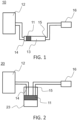
- FIG. 1 schematically represents a first embodiment of a cleaning device 10 with a first filter 11 according to the invention.
- the device 10 for cleaning a gas 12 comprising a plurality of compounds and a target compound, a first compound among the plurality of compounds being tar comprises a container 13 with an inlet 14 and an outlet 15, the gas 12 circulating through through the container 13 from the inlet 14 to the outlet 15.
- the device 10 comprises the first filter 11 positioned between the inlet 14 and the outlet 15 of the container 13, through which the gas 12 circulates, intended to filter the tar.
- the first filter 11 comprises a material absorbing tar and the first filter 11 does not capture said target compound. Tar is found in gaseous, liquid and/or solid form.
- the gas 12 comprises a plurality of elements and it is desirable to remove some of these elements, notably tar, but to retain others, including the target compound, for example HCl or H 2 S.
- first filter 11 comprising a tar-absorbing material makes it possible to absorb the tar, and therefore to remove it from the gas 12, without capturing the elements which one wishes to leave in the gas 12.
- the gas is of the synthesis gas type. This may in particular be syngas.
- the target gas is typically a “non-organic” gas, in particular an acidic gas such as HCl or H 2 S, or a basic gas such as NH 3 .
- the target gas is typically detected by optical spectroscopy.
- Tar depending on the temperature of the air to be analyzed, is found not only in gaseous form, but also in liquid and/or solid form.
- the synthesis gas is at a temperature between 100°C and 1000°C, in particular between 100°C and 800°C, preferably between 100°C and 400°C.
- the gas to be analyzed is at a temperature of 150°C at the inlet of the cleaning device.
- the container 13 can be made of different materials, for example glass or quartz.
- the absorbent material may be a natural material, preferably cotton.
- the absorbent material may be a synthetic material, preferably nylon.
- Cotton and nylon are particularly absorbent materials for tar and it has been found that they are particularly suitable as absorbent material for the first filter 11.
- FIG 2 schematically represents a second embodiment of a cleaning device 20 according to the invention. All elements of the figure 2 are identical to those of the figure 1 , except the container.
- the container is a bottle 23.
- the inlet 14 and outlet 15 of the container are shown at the upper end of the container but could be located, both or only one of the two, on a side face, above the first filter 11.
- the container 13 is a tube comprising two ends, a first among the two ends being the inlet 14 and a second among the two ends being the outlet 15.
- the container 13 in the form of a tube has the advantage of avoiding stagnation of certain elements of the gas 12 in the container 13. There is no dead zone in the container 13. Speed is an important parameter in the device according to the invention to allow good continuous analysis of the gas 12.
- the tube 13 has a substantially constant section between the inlet 14 and the outlet 15.
- the constant section of the tube 13 ensures a constant flow speed of the gas through the tube 13.
- the speed of the gas 12 through the tube 13 is known at any time.
- the tube can be of dimensions that allow the gas inlet flow rate to be controlled at a target speed.
- these dimensions could be a length of 120 mm and an internal diameter of 10 mm.
- a fine geometry, that is to say a relationship between length and diameter of 10 to 15 is advantageous for controlling the inlet flow using drawing means.
- FIG. 3 schematically represents another embodiment of a cleaning device 30 with a tube of non-constant section according to the invention. All elements of the Figure 3 are identical to those of the figure 1 , except for the container referenced here 33.
- the container 33 is a tube which has a non-constant section between the inlet 14 and the outlet 15. Due to the non-constant section of the tube, the flow speed of the gas 12 through the tube varies in relation to the section of the tube. The larger the section, the more the flow speed of the gas 12 decreases and the more the section decreases, the more the flow speed of the gas 12 increases, at the same temperature and pressure.
- FIG 4 schematically represents another embodiment of a cleaning device 40 according to the invention. All elements of the figure 4 are identical to those of the figure 1 .
- the device 40 comprises several first filters 11 arranged successively in the tube. The fact of adding several first filters 11 makes it possible to obtain better filtering of the tars in the gas 12. In fact, the tars not filtered by the first of the first filters 11 must pass through the second, and possibly the third of the first filters 11. .
- the cleaning device 40 is shown with a tube but the container could just as easily be a bottle.
- FIG. 5 schematically represents another embodiment of a cleaning device 50 according to the invention. All elements of the Figure 5 are identical to those of the figure 1 .
- the device 50 comprises several first filters 11 arranged successively in the tube, for example here two, and one of the first filters is longer than the other.
- gas 12 has a longer passage time through the first filter.
- the fact of having a first filter 11 longer along the axis along which the container extends further makes it possible to improve the capacity tar removal.
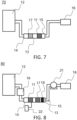
- FIG. 6 schematically represents another embodiment of a cleaning device 60 with a second filter 17 downstream of the first filter 11 according to the invention.
- a second compound among several compounds to be eliminated in gas 12 is water.
- the cleaning device 60 according to the invention comprises the second filter 17 positioned between the inlet 14 and the outlet 15 of the container 13, upstream or downstream of the first filter 11, through which the gas 12 circulates and intended to remove the water from the gas 12.
- the second filter 17 comprises a water adsorbent material.
- first filter 11 and a second filter 17 in the container 13 makes it possible to have both a tar absorbent material and a water adsorbent material, which allows both, in the same container 13, to remove the tars and water from the gas 12.
- the cleaning device 60 is shown with a tube but the container could just as easily be a bottle.
- first filters 11 and second filters 17 can vary, from a first filter 11 to several first filters 11 and/or from a second filter 17 to several second filters 17.
- FIG. 7 schematically represents another embodiment of a cleaning device 70 with a second filter 17 upstream of the first filter 11 according to the invention. All elements of the Figure 7 are identical to those of the Figure 6 . The only difference is in the positioning of the second filter 17 which is this time positioned upstream of the first filter 11 in the container 13. The order in which the first and second filters are positioned in the container has no impact on their filtering capacity.
- the water adsorbent material comprises a neutral and/or acidic particle surface.
- the surface pH of the adsorbent material is therefore less than or equal to 7.0.
- the neutral or acidic particle surface of the water adsorbent material prevents any chemical or physical interaction of the analyte compound, such as HCl, with the material surface.
- the water adsorbent material comprises a neutral and/or basic particle surface.
- the surface pH of the adsorbent material is therefore greater than or equal to 7.0.
- the neutral or basic particle surface of the water adsorbent material prevents any chemical or physical interaction of the analyte compound, such as NH 3 , with the surface of the material.
- the adsorbent material may be a zeolite.
- the surface pH of a zeolite can be controlled by contacting it with an acidic or basic solution.
- a zeolite can have only one type of porosity meaning good homogeneity of pore size.
- FIG 8 schematically represents another embodiment of a cleaning device 80 with a heating device according to the invention. All elements of the figure 8 are identical to those of the Figure 6 .
- the cleaning device 80 comprises a heating device 19 for the gas 12 positioned upstream of the inlet 14 of the container 13.
- the heating of the gas is carried out upstream of the container and the second filter 17 is also heated.
- the temperature of the gas 12 and the second filter 17 is important. In fact, the water must not condense.
- the heating device 19 makes it possible to heat the gas 12 and the second filter 17 so as to maintain the temperature of the second filter 17 above the dew point of the water, which avoids the phenomenon of water condensation.
- the device according to the invention may comprise a cooling device 22 of the first filter 11.
- a first technical effect resulting from the use of the cooling device 22 of the first filter 11 is to increase the condensation of the tars and therefore the more effective removal of tars before the gas 12 leaves through outlet 15. There is an increase in purification efficiency.
- a second technical effect resulting from the use of the cooling device 22 of the first filter 11 is that, in combination with synthetic materials, a drop in temperature prevents certain compounds such as the HCl contained in the gas 12 from reacting with the materials.
- cooling device 22 of the first filter 11 is represented very schematically on the figure 8 .
- This cooling device is advantageous but not obligatory. It does not appear on the other figures but can of course be combined with the elements presented in figures 1 to 7 as well as the Figure 9 .
- the device according to the invention can also comprise a suction device 21 for the gas 12 positioned downstream of the outlet 15 of the container 13.
- the suction arrangement 21 can for example be a pump, and makes it possible to conduct the gas 12 from input 14 to output 15.
- the device according to the invention may comprise an indicator 18 positioned downstream of the second filter 17 and configured to indicate a concentration of water in the gas 12 downstream of the second filter 17 beyond a previously defined threshold concentration. It may, for example, be a silica gel which changes color above a certain water concentration. This indicator 18 makes it possible to show that the second filter 17 is no longer effective enough for elimination.
- the adsorbent material of the second filter 17 adsorbs water, and beyond a certain use, it must be changed or regenerated.
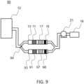
- FIG. 9 schematically represents another embodiment of a cleaning device 90 comprising several containers according to the invention. All elements of the Figure 9 are identical to those of the figure 8 .
- the device 90 further comprises a second container 93, in parallel with the container 13, in which there is a first filter 91 and a second filter 97 (upstream or downstream of the first filter 91, on the Figure 9 it is downstream) as well as an indicator 98.
- the device 90 comprises a diversion finger 94 upstream of the containers 13, 93.
- the diversion finger 94 is positioned towards the container 93, that is to say it prevents the gas 12 from circulating through the container 93. All the gas 12 is therefore directed towards the container 13 which it passes through to be cleaned.
- the indicator 18 of the container 13 indicates a concentration of water in the gas 12 downstream of the second filter 17 beyond a previously defined threshold concentration. It is then necessary to change/regenerate the adsorbent material of the second filter 17.
- the diversion finger 94 is then tilted towards the container 13, that is to say it prevents the gas 12 from circulating through the container 13. the gas 12 is then directed towards the container 93 which it passes through to be cleaned.
- the portion of the container 13 being put out of service it is then easy to change and/or regenerate the adsorbent material of the second filter 17.
- the diversion finger 94 is then switched towards the container 93, c that is to say that it prevents the gas 12 from circulating through the container 93. And it is then possible to carry out the same maneuver as previously for the filters of the container 13.
- This principle is also applicable to several containers.
- the tilting of the diversion finger 94 can also be controlled in a control loop with detection when the indicator 18 of a container indicates a concentration of water in the gas 12 downstream of the second filter 17 beyond a concentration previously defined threshold and tilting of the diversion finger 94 towards said container to direct the gas towards another container.
- FIGS. 10A and 10B represent the infrared spectrum containing 1000ppm of HCl in the pure nitrogen matrix and the infrared spectrum of the gas containing HCl produced by the pyrolysis at 750°C of pure PVC and a mixture of wood and 1% by mass of PVC , sampled with a classic method, in this case using the solvent isopropanol.
- the absorbance is plotted as a function of wavelength.
- FIGS. 11A and 11B represent the infrared spectrum of 1000ppm of HCl in the pure nitrogen matrix and the infrared spectrum of the gas containing HCl produced by the pyrolysis at 750°C of pure PVC and a mixture of wood and 1% by mass of PVC, sampled with the device according to the invention.
- the absorbance is plotted as a function of wavelength.
- FIG 11A shows that by using the device according to the invention to sample HCl in a gas produced by the pyrolysis of pure PVC, one can observe the absorbance peaks which correspond to the HCl peaks in the region 2600 - 2900 cm -1 of the spectrum.
- the process for selective filtration of a gas 12 according to the invention comprising a plurality of compounds, a first compound among the plurality of compounds being tar, the tar being in gaseous, liquid and/or solid form and a target compound, comprises a step of circulating the gas 12 through a container 13 between an inlet 14 of the container and an outlet 15 of the container.
- the method comprises a step of filtering the tar by a first filter 11 positioned between the inlet 14 and the outlet 15 of the container 13 and comprising a material absorbing the tar not capturing said target compound.
- the container 13 may comprise a second filter comprising a water adsorbent material not capturing the target compound and positioned between the inlet 14 and the outlet 15 of the container, upstream or downstream of the first filter.
- the gas 12 circulates through the container, and the second filter is intended to remove the water from gas 12.
- the filtration process then comprises a step of filtering the water by the second filter.
Landscapes
- Chemical & Material Sciences (AREA)
- Engineering & Computer Science (AREA)
- Analytical Chemistry (AREA)
- Health & Medical Sciences (AREA)
- Life Sciences & Earth Sciences (AREA)
- General Physics & Mathematics (AREA)
- Immunology (AREA)
- Physics & Mathematics (AREA)
- Combustion & Propulsion (AREA)
- Biochemistry (AREA)
- General Health & Medical Sciences (AREA)
- Food Science & Technology (AREA)
- Medicinal Chemistry (AREA)
- Pathology (AREA)
- General Chemical & Material Sciences (AREA)
- Oil, Petroleum & Natural Gas (AREA)
- Chemical Kinetics & Catalysis (AREA)
- Sampling And Sample Adjustment (AREA)
- Industrial Gases (AREA)
Claims (13)
- Einheit zur Online-Analyse einer Zielverbindung in einem Gas, dadurch gekennzeichnet, dass sie umfasst:• eine Reinigungsvorrichtung (10, 20, 30, 40, 50, 60, 70, 80, 90) eines Gases (12), eine Vielzahl von Verbindungen umfassend, wobei eine erste Verbindung aus der Vielzahl von Verbindungen Teer ist, eine zweite Verbindung aus der Vielzahl von Verbindungen Wasser ist, und eine Zielverbindung, wobei die Reinigungsvorrichtung umfasst:∘ einen Behälter (13, 93) mit einem Einlass (14) und einem Auslass (15), wobei das Gas (12) durch den Behälter (13, 93) vom Einlass (14) zum Auslass (15) strömt,∘ einen ersten Filter (11, 91), der zwischen dem Einlass (14) und dem Auslass (15) des Behälters (13, 93), durch den das Gas (12) strömt, angeordnet ist, und dazu bestimmt ist, den Teer zu filtern,wobei der erste Filter (11, 91) ein Material umfasst, das den Teer absorbiert,wobei der erste Filter (11, 91) die Zielverbindung nicht auffängt,wobei der Teer in gasförmiger, flüssiger und/oder fester Form vorliegt, undund dass der zweite Filter die Zielverbindung nicht auffängt;o einen zweiten Filter (17, 97), der zwischen dem Einlass (14) und dem Auslass (15) des Behälters (13, 93), durch den das Gas (12) strömt, stromaufwärtig oder stromabwärtig des ersten Filters (11, 91), angeordnet ist, und dazu bestimmt ist, das Wasser aus dem Gas (12) zu entfernen,dadurch, dass der zweite Filter ein Material umfasst, das Wasser adsorbiert,• einen Gasanalysator (16), stromabwärtig der Reinigungsvorrichtung, und konfiguriert, um die Konzentration der Zielverbindung im Gas zu messen,und dass die Zielverbindung aus HCl und NH3 ausgewählt wird.
- Einheit zur Online-Analyse nach Anspruch 1, dadurch gekennzeichnet, dass das absorbierende Material ein natürliches Material ist, vorzugsweise Baumwolle.
- Einheit zur Online-Analyse nach Anspruch 1, dadurch gekennzeichnet, dass das absorbierende Material ein synthetisches Material ist, vorzugsweise Nylon.
- Einheit zur Online-Analyse nach einem der vorhergehenden Ansprüche, wobei eine dritte Verbindung aus der Vielzahl von Verbindungen ein saures Gas ist, dadurch gekennzeichnet, dass das Material, das Wasser adsorbiert, eine neutrale oder saure Partikeloberfläche umfasst.
- Einheit zur Online-Analyse nach einem der vorhergehenden Ansprüche, dadurch gekennzeichnet, dass das adsorbierende Material ein Zeolith ist.
- Einheit zur Online-Analyse nach einem der vorhergehenden Ansprüche, dadurch gekennzeichnet, dass der Behälter (13, 93) ein Rohr ist, das zwei Enden umfasst, wobei ein erstes von den zwei Enden der Einlass ist und ein zweites von den zwei Enden der Auslass ist.
- Einheit zur Online-Analyse nach Anspruch 6, dadurch gekennzeichnet, dass das Rohr einen im Wesentlichen konstanten Querschnitt zwischen dem Einlass und dem Auslass aufweist.
- Einheit zur Online-Analyse nach Anspruch 6, dadurch gekennzeichnet, dass das Rohr einen nicht konstanten Querschnitt zwischen dem Einlass und dem Auslass aufweist.
- Einheit zur Online-Analyse nach einem der Ansprüche 4 bis 8, dadurch gekennzeichnet, dass sie eine Vorrichtung zum Wärmen (19) des Gases umfasst, die stromaufwärtig des Einlasses (14) des Behälters (13, 93) angeordnet ist.
- Einheit zur Online-Analyse nach einem der vorhergehenden Ansprüche, dadurch gekennzeichnet, dass sie eine Vorrichtung zur Kühlung (22) des ersten Filters (11) umfasst.
- Einheit zur Online-Analyse nach einem der vorhergehenden Ansprüche, dadurch gekennzeichnet, dass sie eine Vorrichtung zum Ansaugen (21) des Gases (12) umfasst, die stromabwärtig des Auslasses (15) des Behälters (13, 93) angeordnet ist.
- Einheit zur Online-Analyse nach einem der Ansprüche 4 bis 11, dadurch gekennzeichnet, dass sie einen Indikator (18, 98) umfasst, der stromabwärtig des zweiten Filters (17, 97) angeordnet ist und konfiguriert ist, um eine Wasserkonzentration im Gas (12) stromabwärtig des zweiten Filters (17, 97) anzuzeigen, die über eine zuvor definierte Konzentrationsschwelle hinausgeht.
- Verfahren zum selektiven Filtern eines Gases (12) im Hinblick auf seine Analyse, wobei das Gas eine Vielzahl von Verbindungen umfasst, eine erste Verbindung aus der Vielzahl von Verbindungen, die Teer ist und der Teer in gasförmiger, flüssiger und/oder fester Form vorliegt, eine zweite Verbindung, die Wasser ist, und eine Zielverbindung, die aus HCl und NH3 ausgewählt wird, dadurch gekennzeichnet, dass es die folgenden Schritte umfasst:• Strömung eines Gases (12) durch einen Behälter (13, 93) zwischen einem Einlass (14) des Behälters und einem Auslass (15) des Behälters,• Filterung des Teers durch einen ersten Filter (11, 91), der zwischen dem Einlass (14) und dem Auslass (15) des Behälters (13, 93) angeordnet ist, und ein Material umfasst, das Teer absorbiert und die Zielverbindung nicht auffängt,• Filterung des Wassers durch einen zweiten Filter, der ein Material umfasst, das Wasser adsorbiert und die Zielverbindung nicht auffängt, und zwischen dem Einlass (14) und dem Auslass (15) des Behälters (13, 93), stromaufwärtig oder stromabwärtig des ersten Filters (11, 91) angeordnet ist.
Applications Claiming Priority (2)
| Application Number | Priority Date | Filing Date | Title |
|---|---|---|---|
| FR1757131A FR3069453B1 (fr) | 2017-07-27 | 2017-07-27 | Dispositif de nettoyage d'un gaz pour analyse en ligne |
| PCT/EP2018/070193 WO2019020698A1 (fr) | 2017-07-27 | 2018-07-25 | Dispositif de nettoyage d'un gaz pour analyse en ligne |
Publications (2)
| Publication Number | Publication Date |
|---|---|
| EP3658255A1 EP3658255A1 (de) | 2020-06-03 |
| EP3658255B1 true EP3658255B1 (de) | 2024-07-24 |
Family
ID=59930574
Family Applications (1)
| Application Number | Title | Priority Date | Filing Date |
|---|---|---|---|
| EP18743813.0A Active EP3658255B1 (de) | 2017-07-27 | 2018-07-25 | Vorrichtung zur reinigung eines gases für online-analyse |
Country Status (3)
| Country | Link |
|---|---|
| EP (1) | EP3658255B1 (de) |
| FR (1) | FR3069453B1 (de) |
| WO (1) | WO2019020698A1 (de) |
Families Citing this family (1)
| Publication number | Priority date | Publication date | Assignee | Title |
|---|---|---|---|---|
| CN112619302A (zh) * | 2020-12-07 | 2021-04-09 | 安徽普源分离机械制造有限公司 | 一种气体检测用过滤装置及离心机氧含量检测系统 |
Citations (4)
| Publication number | Priority date | Publication date | Assignee | Title |
|---|---|---|---|---|
| FR2778743A1 (fr) * | 1998-05-12 | 1999-11-19 | Elf Exploration Prod | Analyseur pour la mesure en continu de l'h2s contenu dans un gaz et dispositif l'incluant pour la regulation du debit d'air injecte dans un reacteur d'oxydation d'h2s en soufre |
| US20020048818A1 (en) * | 1998-11-25 | 2002-04-25 | Hitachi, Ltd. | Chemical monitoring method and apparatus, and incinerator |
| WO2015195087A1 (en) * | 2014-06-16 | 2015-12-23 | Mustang Sampling, Llc | Low pressure biogas sample takeoff and conditioning system |
| FR3032035A1 (fr) * | 2015-01-27 | 2016-07-29 | Arkema France | Dispositif transportable de mesure en ligne de la concentration en sulfure d'hydrogene d'un effluent gazeux |
Family Cites Families (7)
| Publication number | Priority date | Publication date | Assignee | Title |
|---|---|---|---|---|
| US4272486A (en) * | 1979-02-14 | 1981-06-09 | Beckman Instruments, Inc. | Interference reactor to provide selective SO2 measurement by fluorescent methodology |
| DE3763717D1 (de) * | 1986-02-18 | 1990-08-23 | Siemens Ag | Verfahren zur reinhaltung der messleitungen an emissions-messeinrichtungen, anwendung des verfahrens und gasentnahmesonde zu seiner durchfuehrung. |
| DE3716350A1 (de) * | 1987-05-15 | 1988-12-01 | Groeger & Obst Mess Regeltech | Verfahren und einrichtung zur aufbereitung eines zu analysierenden gases |
| US7140232B2 (en) * | 2002-12-16 | 2006-11-28 | Radiodetection Limited | Method and apparatus for multiple gas sensor |
| FR2960446B1 (fr) * | 2010-05-25 | 2012-07-20 | Saint Gobain Quartz Sas | Media piegeur pour purificateur d'air |
| EP2561916A1 (de) * | 2011-08-24 | 2013-02-27 | Neste Oil Oyj | Verfahren zur Naphthalenentfernung |
| WO2013133872A1 (en) * | 2011-11-30 | 2013-09-12 | The Regents Of The University Of California | Detection and measurement of volatile organic compounds |
-
2017
- 2017-07-27 FR FR1757131A patent/FR3069453B1/fr active Active
-
2018
- 2018-07-25 WO PCT/EP2018/070193 patent/WO2019020698A1/fr not_active Ceased
- 2018-07-25 EP EP18743813.0A patent/EP3658255B1/de active Active
Patent Citations (4)
| Publication number | Priority date | Publication date | Assignee | Title |
|---|---|---|---|---|
| FR2778743A1 (fr) * | 1998-05-12 | 1999-11-19 | Elf Exploration Prod | Analyseur pour la mesure en continu de l'h2s contenu dans un gaz et dispositif l'incluant pour la regulation du debit d'air injecte dans un reacteur d'oxydation d'h2s en soufre |
| US20020048818A1 (en) * | 1998-11-25 | 2002-04-25 | Hitachi, Ltd. | Chemical monitoring method and apparatus, and incinerator |
| WO2015195087A1 (en) * | 2014-06-16 | 2015-12-23 | Mustang Sampling, Llc | Low pressure biogas sample takeoff and conditioning system |
| FR3032035A1 (fr) * | 2015-01-27 | 2016-07-29 | Arkema France | Dispositif transportable de mesure en ligne de la concentration en sulfure d'hydrogene d'un effluent gazeux |
Also Published As
| Publication number | Publication date |
|---|---|
| FR3069453A1 (fr) | 2019-02-01 |
| EP3658255A1 (de) | 2020-06-03 |
| WO2019020698A1 (fr) | 2019-01-31 |
| FR3069453B1 (fr) | 2026-02-06 |
Similar Documents
| Publication | Publication Date | Title |
|---|---|---|
| CA2672272A1 (fr) | Dispositif et procede de mesures couplees permettant un suivi global et en continu de traces de goudrons presentes dans un flux gazeux | |
| EP1833593B1 (de) | Vorrichtung zur reinigung eines kondensierbare dämpfe enthaltenden gasstroms | |
| WO2009109725A2 (fr) | Dispositif de sechage d'un gaz, notamment de l'air, et son application a un dispositif et procede de prelevement d'un echantillon de gaz. | |
| JP5049214B2 (ja) | 汚染物を測定、管理するためのシステムおよび方法 | |
| CA2672020A1 (fr) | Dispositif et procede de mesure continue de la concentration en goudrons dans un flux gazeux | |
| Poloncarzova et al. | Effective Purification of Biogas by a Condensing‐Liquid Membrane | |
| CN101776661A (zh) | 一种发动机尾气中单环芳香烃类污染物的检测方法 | |
| WO2009153264A1 (fr) | Dispositif et procede de mesure continue en ligne de la concentration totale en goudrons dans un flux gazeux pouvant être a haute temperature | |
| EP3658255B1 (de) | Vorrichtung zur reinigung eines gases für online-analyse | |
| EP0948458B1 (de) | Verfahren zur reinigung eines kryogenischen fluid mittels filtration und adsorption | |
| EP1706727A1 (de) | Verfahren zur messung gasförmiger spezies durch derivation | |
| CN113970600A (zh) | 一种加热卷烟烟气在线分析检测装置及方法 | |
| WO2009016279A2 (fr) | Procede et dispositif de detection et de quantification d'un compose chimique dans un courant fluide | |
| FR3015685A1 (fr) | Dispositif et procede de mesure en continu de la concentration totale en goudrons d'un gaz chaud | |
| CN206258374U (zh) | 一种测汞系统 | |
| KR102302601B1 (ko) | 굴뚝 배기가스로부터 암모니아의 연속 측정장치 | |
| FR2932889A1 (fr) | Dispositif et procede pour l'estimation precise bornee pseudo-continue et en ligne de la concentration totale en goudrons dans un flux gazeux pouvant etre a haute temperature | |
| Wurl et al. | Analysis of dissolved and particulate organic carbon with the HTCO technique | |
| WO2021234291A2 (fr) | Dispositif pour le traitement d'air comprenant au moins un composé organique volatil | |
| FR3118718A1 (fr) | procédé non destructif de determination de la capacité residuelle d’arrêt d’un filtre adsorbant et banc d’essai associé | |
| Grover et al. | Modifications to the Sunset Laboratory carbon aerosol monitor for the simultaneous measurement of PM2. 5 nonvolatile and semi-volatile carbonaceous material | |
| FR2736845A1 (fr) | Procede et appareillage et installation pour le traitement d'effluents gazeux contenant des composes organiques volatils | |
| FR2873812A1 (fr) | Dispositif de prelevement de composes volatils | |
| GB2456017A (en) | Combustion analyser and method for combustion analysing a sample | |
| Večeřa et al. | Wet Preconcentration Techniques for “Real Time” Determination of Gaseous Pollutants in Ambient Air |
Legal Events
| Date | Code | Title | Description |
|---|---|---|---|
| STAA | Information on the status of an ep patent application or granted ep patent |
Free format text: STATUS: UNKNOWN |
|
| STAA | Information on the status of an ep patent application or granted ep patent |
Free format text: STATUS: THE INTERNATIONAL PUBLICATION HAS BEEN MADE |
|
| PUAI | Public reference made under article 153(3) epc to a published international application that has entered the european phase |
Free format text: ORIGINAL CODE: 0009012 |
|
| STAA | Information on the status of an ep patent application or granted ep patent |
Free format text: STATUS: REQUEST FOR EXAMINATION WAS MADE |
|
| 17P | Request for examination filed |
Effective date: 20200109 |
|
| AK | Designated contracting states |
Kind code of ref document: A1 Designated state(s): AL AT BE BG CH CY CZ DE DK EE ES FI FR GB GR HR HU IE IS IT LI LT LU LV MC MK MT NL NO PL PT RO RS SE SI SK SM TR |
|
| AX | Request for extension of the european patent |
Extension state: BA ME |
|
| DAV | Request for validation of the european patent (deleted) | ||
| DAX | Request for extension of the european patent (deleted) | ||
| STAA | Information on the status of an ep patent application or granted ep patent |
Free format text: STATUS: EXAMINATION IS IN PROGRESS |
|
| 17Q | First examination report despatched |
Effective date: 20220623 |
|
| RAP1 | Party data changed (applicant data changed or rights of an application transferred) |
Owner name: SUEZ INTERNATIONAL |
|
| GRAP | Despatch of communication of intention to grant a patent |
Free format text: ORIGINAL CODE: EPIDOSNIGR1 |
|
| STAA | Information on the status of an ep patent application or granted ep patent |
Free format text: STATUS: GRANT OF PATENT IS INTENDED |
|
| INTG | Intention to grant announced |
Effective date: 20231108 |
|
| GRAJ | Information related to disapproval of communication of intention to grant by the applicant or resumption of examination proceedings by the epo deleted |
Free format text: ORIGINAL CODE: EPIDOSDIGR1 |
|
| STAA | Information on the status of an ep patent application or granted ep patent |
Free format text: STATUS: EXAMINATION IS IN PROGRESS |
|
| INTC | Intention to grant announced (deleted) | ||
| GRAP | Despatch of communication of intention to grant a patent |
Free format text: ORIGINAL CODE: EPIDOSNIGR1 |
|
| STAA | Information on the status of an ep patent application or granted ep patent |
Free format text: STATUS: GRANT OF PATENT IS INTENDED |
|
| INTG | Intention to grant announced |
Effective date: 20240430 |
|
| GRAS | Grant fee paid |
Free format text: ORIGINAL CODE: EPIDOSNIGR3 |
|
| GRAA | (expected) grant |
Free format text: ORIGINAL CODE: 0009210 |
|
| STAA | Information on the status of an ep patent application or granted ep patent |
Free format text: STATUS: THE PATENT HAS BEEN GRANTED |
|
| AK | Designated contracting states |
Kind code of ref document: B1 Designated state(s): AL AT BE BG CH CY CZ DE DK EE ES FI FR GB GR HR HU IE IS IT LI LT LU LV MC MK MT NL NO PL PT RO RS SE SI SK SM TR |
|
| REG | Reference to a national code |
Ref country code: GB Ref legal event code: FG4D Free format text: NOT ENGLISH |
|
| REG | Reference to a national code |
Ref country code: CH Ref legal event code: EP |
|
| REG | Reference to a national code |
Ref country code: IE Ref legal event code: FG4D Free format text: LANGUAGE OF EP DOCUMENT: FRENCH Ref country code: DE Ref legal event code: R096 Ref document number: 602018072179 Country of ref document: DE |
|
| P01 | Opt-out of the competence of the unified patent court (upc) registered |
Free format text: CASE NUMBER: APP_43148/2024 Effective date: 20240723 |
|
| REG | Reference to a national code |
Ref country code: LT Ref legal event code: MG9D |
|
| REG | Reference to a national code |
Ref country code: NL Ref legal event code: MP Effective date: 20240724 |
|
| PG25 | Lapsed in a contracting state [announced via postgrant information from national office to epo] |
Ref country code: PT Free format text: LAPSE BECAUSE OF FAILURE TO SUBMIT A TRANSLATION OF THE DESCRIPTION OR TO PAY THE FEE WITHIN THE PRESCRIBED TIME-LIMIT Effective date: 20241125 |
|
| REG | Reference to a national code |
Ref country code: AT Ref legal event code: MK05 Ref document number: 1705803 Country of ref document: AT Kind code of ref document: T Effective date: 20240724 |
|
| PG25 | Lapsed in a contracting state [announced via postgrant information from national office to epo] |
Ref country code: NL Free format text: LAPSE BECAUSE OF FAILURE TO SUBMIT A TRANSLATION OF THE DESCRIPTION OR TO PAY THE FEE WITHIN THE PRESCRIBED TIME-LIMIT Effective date: 20240724 |
|
| PG25 | Lapsed in a contracting state [announced via postgrant information from national office to epo] |
Ref country code: PT Free format text: LAPSE BECAUSE OF FAILURE TO SUBMIT A TRANSLATION OF THE DESCRIPTION OR TO PAY THE FEE WITHIN THE PRESCRIBED TIME-LIMIT Effective date: 20241125 Ref country code: NL Free format text: LAPSE BECAUSE OF FAILURE TO SUBMIT A TRANSLATION OF THE DESCRIPTION OR TO PAY THE FEE WITHIN THE PRESCRIBED TIME-LIMIT Effective date: 20240724 |
|
| PG25 | Lapsed in a contracting state [announced via postgrant information from national office to epo] |
Ref country code: NO Free format text: LAPSE BECAUSE OF FAILURE TO SUBMIT A TRANSLATION OF THE DESCRIPTION OR TO PAY THE FEE WITHIN THE PRESCRIBED TIME-LIMIT Effective date: 20241024 |
|
| PG25 | Lapsed in a contracting state [announced via postgrant information from national office to epo] |
Ref country code: GR Free format text: LAPSE BECAUSE OF FAILURE TO SUBMIT A TRANSLATION OF THE DESCRIPTION OR TO PAY THE FEE WITHIN THE PRESCRIBED TIME-LIMIT Effective date: 20241025 Ref country code: FI Free format text: LAPSE BECAUSE OF FAILURE TO SUBMIT A TRANSLATION OF THE DESCRIPTION OR TO PAY THE FEE WITHIN THE PRESCRIBED TIME-LIMIT Effective date: 20240724 Ref country code: PL Free format text: LAPSE BECAUSE OF FAILURE TO SUBMIT A TRANSLATION OF THE DESCRIPTION OR TO PAY THE FEE WITHIN THE PRESCRIBED TIME-LIMIT Effective date: 20240724 |
|
| PG25 | Lapsed in a contracting state [announced via postgrant information from national office to epo] |
Ref country code: BG Free format text: LAPSE BECAUSE OF FAILURE TO SUBMIT A TRANSLATION OF THE DESCRIPTION OR TO PAY THE FEE WITHIN THE PRESCRIBED TIME-LIMIT Effective date: 20240724 |
|
| PG25 | Lapsed in a contracting state [announced via postgrant information from national office to epo] |
Ref country code: LV Free format text: LAPSE BECAUSE OF FAILURE TO SUBMIT A TRANSLATION OF THE DESCRIPTION OR TO PAY THE FEE WITHIN THE PRESCRIBED TIME-LIMIT Effective date: 20240724 |
|
| PG25 | Lapsed in a contracting state [announced via postgrant information from national office to epo] |
Ref country code: IS Free format text: LAPSE BECAUSE OF FAILURE TO SUBMIT A TRANSLATION OF THE DESCRIPTION OR TO PAY THE FEE WITHIN THE PRESCRIBED TIME-LIMIT Effective date: 20241124 Ref country code: AT Free format text: LAPSE BECAUSE OF FAILURE TO SUBMIT A TRANSLATION OF THE DESCRIPTION OR TO PAY THE FEE WITHIN THE PRESCRIBED TIME-LIMIT Effective date: 20240724 |
|
| PG25 | Lapsed in a contracting state [announced via postgrant information from national office to epo] |
Ref country code: HR Free format text: LAPSE BECAUSE OF FAILURE TO SUBMIT A TRANSLATION OF THE DESCRIPTION OR TO PAY THE FEE WITHIN THE PRESCRIBED TIME-LIMIT Effective date: 20240724 |
|
| PG25 | Lapsed in a contracting state [announced via postgrant information from national office to epo] |
Ref country code: RS Free format text: LAPSE BECAUSE OF FAILURE TO SUBMIT A TRANSLATION OF THE DESCRIPTION OR TO PAY THE FEE WITHIN THE PRESCRIBED TIME-LIMIT Effective date: 20241024 Ref country code: ES Free format text: LAPSE BECAUSE OF FAILURE TO SUBMIT A TRANSLATION OF THE DESCRIPTION OR TO PAY THE FEE WITHIN THE PRESCRIBED TIME-LIMIT Effective date: 20240724 |
|
| PG25 | Lapsed in a contracting state [announced via postgrant information from national office to epo] |
Ref country code: RS Free format text: LAPSE BECAUSE OF FAILURE TO SUBMIT A TRANSLATION OF THE DESCRIPTION OR TO PAY THE FEE WITHIN THE PRESCRIBED TIME-LIMIT Effective date: 20241024 Ref country code: PL Free format text: LAPSE BECAUSE OF FAILURE TO SUBMIT A TRANSLATION OF THE DESCRIPTION OR TO PAY THE FEE WITHIN THE PRESCRIBED TIME-LIMIT Effective date: 20240724 Ref country code: NO Free format text: LAPSE BECAUSE OF FAILURE TO SUBMIT A TRANSLATION OF THE DESCRIPTION OR TO PAY THE FEE WITHIN THE PRESCRIBED TIME-LIMIT Effective date: 20241024 Ref country code: LV Free format text: LAPSE BECAUSE OF FAILURE TO SUBMIT A TRANSLATION OF THE DESCRIPTION OR TO PAY THE FEE WITHIN THE PRESCRIBED TIME-LIMIT Effective date: 20240724 Ref country code: IS Free format text: LAPSE BECAUSE OF FAILURE TO SUBMIT A TRANSLATION OF THE DESCRIPTION OR TO PAY THE FEE WITHIN THE PRESCRIBED TIME-LIMIT Effective date: 20241124 Ref country code: HR Free format text: LAPSE BECAUSE OF FAILURE TO SUBMIT A TRANSLATION OF THE DESCRIPTION OR TO PAY THE FEE WITHIN THE PRESCRIBED TIME-LIMIT Effective date: 20240724 Ref country code: GR Free format text: LAPSE BECAUSE OF FAILURE TO SUBMIT A TRANSLATION OF THE DESCRIPTION OR TO PAY THE FEE WITHIN THE PRESCRIBED TIME-LIMIT Effective date: 20241025 Ref country code: FI Free format text: LAPSE BECAUSE OF FAILURE TO SUBMIT A TRANSLATION OF THE DESCRIPTION OR TO PAY THE FEE WITHIN THE PRESCRIBED TIME-LIMIT Effective date: 20240724 Ref country code: ES Free format text: LAPSE BECAUSE OF FAILURE TO SUBMIT A TRANSLATION OF THE DESCRIPTION OR TO PAY THE FEE WITHIN THE PRESCRIBED TIME-LIMIT Effective date: 20240724 Ref country code: BG Free format text: LAPSE BECAUSE OF FAILURE TO SUBMIT A TRANSLATION OF THE DESCRIPTION OR TO PAY THE FEE WITHIN THE PRESCRIBED TIME-LIMIT Effective date: 20240724 Ref country code: AT Free format text: LAPSE BECAUSE OF FAILURE TO SUBMIT A TRANSLATION OF THE DESCRIPTION OR TO PAY THE FEE WITHIN THE PRESCRIBED TIME-LIMIT Effective date: 20240724 |
|
| REG | Reference to a national code |
Ref country code: DE Ref legal event code: R119 Ref document number: 602018072179 Country of ref document: DE |
|
| REG | Reference to a national code |
Ref country code: CH Ref legal event code: PL |
|
| PG25 | Lapsed in a contracting state [announced via postgrant information from national office to epo] |
Ref country code: LU Free format text: LAPSE BECAUSE OF NON-PAYMENT OF DUE FEES Effective date: 20240725 |
|
| PG25 | Lapsed in a contracting state [announced via postgrant information from national office to epo] |
Ref country code: LU Free format text: LAPSE BECAUSE OF NON-PAYMENT OF DUE FEES Effective date: 20240725 |
|
| PG25 | Lapsed in a contracting state [announced via postgrant information from national office to epo] |
Ref country code: DE Free format text: LAPSE BECAUSE OF NON-PAYMENT OF DUE FEES Effective date: 20250201 |
|
| PG25 | Lapsed in a contracting state [announced via postgrant information from national office to epo] |
Ref country code: RO Free format text: LAPSE BECAUSE OF FAILURE TO SUBMIT A TRANSLATION OF THE DESCRIPTION OR TO PAY THE FEE WITHIN THE PRESCRIBED TIME-LIMIT Effective date: 20240724 Ref country code: DK Free format text: LAPSE BECAUSE OF FAILURE TO SUBMIT A TRANSLATION OF THE DESCRIPTION OR TO PAY THE FEE WITHIN THE PRESCRIBED TIME-LIMIT Effective date: 20240724 Ref country code: SM Free format text: LAPSE BECAUSE OF FAILURE TO SUBMIT A TRANSLATION OF THE DESCRIPTION OR TO PAY THE FEE WITHIN THE PRESCRIBED TIME-LIMIT Effective date: 20240724 |
|
| PG25 | Lapsed in a contracting state [announced via postgrant information from national office to epo] |
Ref country code: MC Free format text: LAPSE BECAUSE OF FAILURE TO SUBMIT A TRANSLATION OF THE DESCRIPTION OR TO PAY THE FEE WITHIN THE PRESCRIBED TIME-LIMIT Effective date: 20240724 Ref country code: BE Free format text: LAPSE BECAUSE OF NON-PAYMENT OF DUE FEES Effective date: 20240731 Ref country code: CH Free format text: LAPSE BECAUSE OF NON-PAYMENT OF DUE FEES Effective date: 20240731 Ref country code: EE Free format text: LAPSE BECAUSE OF FAILURE TO SUBMIT A TRANSLATION OF THE DESCRIPTION OR TO PAY THE FEE WITHIN THE PRESCRIBED TIME-LIMIT Effective date: 20240724 |
|
| PG25 | Lapsed in a contracting state [announced via postgrant information from national office to epo] |
Ref country code: CZ Free format text: LAPSE BECAUSE OF FAILURE TO SUBMIT A TRANSLATION OF THE DESCRIPTION OR TO PAY THE FEE WITHIN THE PRESCRIBED TIME-LIMIT Effective date: 20240724 |
|
| PG25 | Lapsed in a contracting state [announced via postgrant information from national office to epo] |
Ref country code: SK Free format text: LAPSE BECAUSE OF FAILURE TO SUBMIT A TRANSLATION OF THE DESCRIPTION OR TO PAY THE FEE WITHIN THE PRESCRIBED TIME-LIMIT Effective date: 20240724 |
|
| PLBE | No opposition filed within time limit |
Free format text: ORIGINAL CODE: 0009261 |
|
| STAA | Information on the status of an ep patent application or granted ep patent |
Free format text: STATUS: NO OPPOSITION FILED WITHIN TIME LIMIT |
|
| REG | Reference to a national code |
Ref country code: BE Ref legal event code: MM Effective date: 20240731 |
|
| 26N | No opposition filed |
Effective date: 20250425 |
|
| PGFP | Annual fee paid to national office [announced via postgrant information from national office to epo] |
Ref country code: FR Payment date: 20250513 Year of fee payment: 8 |
|
| PG25 | Lapsed in a contracting state [announced via postgrant information from national office to epo] |
Ref country code: IE Free format text: LAPSE BECAUSE OF NON-PAYMENT OF DUE FEES Effective date: 20240725 |
|
| PG25 | Lapsed in a contracting state [announced via postgrant information from national office to epo] |
Ref country code: SE Free format text: LAPSE BECAUSE OF FAILURE TO SUBMIT A TRANSLATION OF THE DESCRIPTION OR TO PAY THE FEE WITHIN THE PRESCRIBED TIME-LIMIT Effective date: 20240724 |
|
| PGFP | Annual fee paid to national office [announced via postgrant information from national office to epo] |
Ref country code: IT Payment date: 20250724 Year of fee payment: 8 |
|
| PGFP | Annual fee paid to national office [announced via postgrant information from national office to epo] |
Ref country code: GB Payment date: 20250722 Year of fee payment: 8 |
|
| PG25 | Lapsed in a contracting state [announced via postgrant information from national office to epo] |
Ref country code: CY Free format text: LAPSE BECAUSE OF FAILURE TO SUBMIT A TRANSLATION OF THE DESCRIPTION OR TO PAY THE FEE WITHIN THE PRESCRIBED TIME-LIMIT; INVALID AB INITIO Effective date: 20180725 |
|
| PG25 | Lapsed in a contracting state [announced via postgrant information from national office to epo] |
Ref country code: HU Free format text: LAPSE BECAUSE OF FAILURE TO SUBMIT A TRANSLATION OF THE DESCRIPTION OR TO PAY THE FEE WITHIN THE PRESCRIBED TIME-LIMIT; INVALID AB INITIO Effective date: 20180725 |