EP1530981B1 - Verfahren zur Herstellung einer niederohmigen elektrischen Druckkontaktverbindung zwischen der Ringelektrode und dem Leiterdraht - Google Patents
Verfahren zur Herstellung einer niederohmigen elektrischen Druckkontaktverbindung zwischen der Ringelektrode und dem Leiterdraht Download PDFInfo
- Publication number
- EP1530981B1 EP1530981B1 EP04257012A EP04257012A EP1530981B1 EP 1530981 B1 EP1530981 B1 EP 1530981B1 EP 04257012 A EP04257012 A EP 04257012A EP 04257012 A EP04257012 A EP 04257012A EP 1530981 B1 EP1530981 B1 EP 1530981B1
- Authority
- EP
- European Patent Office
- Prior art keywords
- shaft
- tip section
- lead wire
- ring electrode
- electrode lead
- Prior art date
- Legal status (The legal status is an assumption and is not a legal conclusion. Google has not performed a legal analysis and makes no representation as to the accuracy of the status listed.)
- Expired - Lifetime
Links
Images


Classifications
-
- A—HUMAN NECESSITIES
- A61—MEDICAL OR VETERINARY SCIENCE; HYGIENE
- A61B—DIAGNOSIS; SURGERY; IDENTIFICATION
- A61B18/00—Surgical instruments, devices or methods for transferring non-mechanical forms of energy to or from the body
- A61B18/04—Surgical instruments, devices or methods for transferring non-mechanical forms of energy to or from the body by heating
- A61B18/12—Surgical instruments, devices or methods for transferring non-mechanical forms of energy to or from the body by heating by passing a current through the tissue to be heated, e.g. high-frequency current
- A61B18/14—Probes or electrodes therefor
-
- A—HUMAN NECESSITIES
- A61—MEDICAL OR VETERINARY SCIENCE; HYGIENE
- A61N—ELECTROTHERAPY; MAGNETOTHERAPY; RADIATION THERAPY; ULTRASOUND THERAPY
- A61N1/00—Electrotherapy; Circuits therefor
- A61N1/02—Details
- A61N1/04—Electrodes
- A61N1/05—Electrodes for implantation or insertion into the body, e.g. heart electrode
- A61N1/056—Transvascular endocardial electrode systems
-
- Y—GENERAL TAGGING OF NEW TECHNOLOGICAL DEVELOPMENTS; GENERAL TAGGING OF CROSS-SECTIONAL TECHNOLOGIES SPANNING OVER SEVERAL SECTIONS OF THE IPC; TECHNICAL SUBJECTS COVERED BY FORMER USPC CROSS-REFERENCE ART COLLECTIONS [XRACs] AND DIGESTS
- Y10—TECHNICAL SUBJECTS COVERED BY FORMER USPC
- Y10T—TECHNICAL SUBJECTS COVERED BY FORMER US CLASSIFICATION
- Y10T29/00—Metal working
- Y10T29/49—Method of mechanical manufacture
- Y10T29/49002—Electrical device making
- Y10T29/4902—Electromagnet, transformer or inductor
- Y10T29/49071—Electromagnet, transformer or inductor by winding or coiling
-
- Y—GENERAL TAGGING OF NEW TECHNOLOGICAL DEVELOPMENTS; GENERAL TAGGING OF CROSS-SECTIONAL TECHNOLOGIES SPANNING OVER SEVERAL SECTIONS OF THE IPC; TECHNICAL SUBJECTS COVERED BY FORMER USPC CROSS-REFERENCE ART COLLECTIONS [XRACs] AND DIGESTS
- Y10—TECHNICAL SUBJECTS COVERED BY FORMER USPC
- Y10T—TECHNICAL SUBJECTS COVERED BY FORMER US CLASSIFICATION
- Y10T29/00—Metal working
- Y10T29/49—Method of mechanical manufacture
- Y10T29/49002—Electrical device making
- Y10T29/49117—Conductor or circuit manufacturing
- Y10T29/49169—Assembling electrical component directly to terminal or elongated conductor
-
- Y—GENERAL TAGGING OF NEW TECHNOLOGICAL DEVELOPMENTS; GENERAL TAGGING OF CROSS-SECTIONAL TECHNOLOGIES SPANNING OVER SEVERAL SECTIONS OF THE IPC; TECHNICAL SUBJECTS COVERED BY FORMER USPC CROSS-REFERENCE ART COLLECTIONS [XRACs] AND DIGESTS
- Y10—TECHNICAL SUBJECTS COVERED BY FORMER USPC
- Y10T—TECHNICAL SUBJECTS COVERED BY FORMER US CLASSIFICATION
- Y10T29/00—Metal working
- Y10T29/49—Method of mechanical manufacture
- Y10T29/49002—Electrical device making
- Y10T29/49117—Conductor or circuit manufacturing
- Y10T29/49174—Assembling terminal to elongated conductor
-
- Y—GENERAL TAGGING OF NEW TECHNOLOGICAL DEVELOPMENTS; GENERAL TAGGING OF CROSS-SECTIONAL TECHNOLOGIES SPANNING OVER SEVERAL SECTIONS OF THE IPC; TECHNICAL SUBJECTS COVERED BY FORMER USPC CROSS-REFERENCE ART COLLECTIONS [XRACs] AND DIGESTS
- Y10—TECHNICAL SUBJECTS COVERED BY FORMER USPC
- Y10T—TECHNICAL SUBJECTS COVERED BY FORMER US CLASSIFICATION
- Y10T29/00—Metal working
- Y10T29/49—Method of mechanical manufacture
- Y10T29/49002—Electrical device making
- Y10T29/49117—Conductor or circuit manufacturing
- Y10T29/49174—Assembling terminal to elongated conductor
- Y10T29/49181—Assembling terminal to elongated conductor by deforming
- Y10T29/49185—Assembling terminal to elongated conductor by deforming of terminal
Definitions
- This invention relates to electrophysiology catheters and, in particular, to an improved method for attaching ring electrodes to the tip section of an electrophysiology catheter shaft.
- Electrophysiology catheters have been in common use in medical practice for many years. They are used to map and stimulate electrical activity in the heart and to ablate sites of aberrant electrical activity.
- ring electrodes are metal rings positioned at various intervals along the length of the tip section.
- the ring electrodes are electrically connected, via electrode lead wires which extend through a lumen in the catheter, to electrical instruments, e.g., a monitor, stimulator or source of energy, e.g., RF energy, for ablation.
- a conventional method for making the electrical connection between an electrode lead wire and a ring electrode is to draw the electric lead wire out of a lumen in the tip section through an exit hole that extends from the lumen to the side surface of the shaft of the catheter tip.
- the distal end of the electrode lead wire, stripped of any non-conductive coating, is then welded or soldered onto the inner surface of a ring electrode.
- the ring electrode is then slipped over the tip shaft to a position directly over the exit hole while drawing the electrode lead wire back into the lumen.
- the ring electrode is then secured in place, e.g., by swaging or by the application of an appropriate adhesive.
- a resin e.g., polyurethane resin, is often applied to the margins or edges of the ring electrode to assure a smooth transition between the outer circumferential surface of the ring electrode and the outer circumferential surface of the catheter shaft.
- ring electrodes mounted by the conventional method tend to "pull away" from the shaft of the tip section, i.e., the edge of the ring electrode tends to separate from the surface of the catheter tip shaft along the outside of the curve, during tight bending of the tip section.
- a method as set out in the preamble of claim 1 is disclosed in US 4, 592, 372 .
- the present invention provides a method for attaching a ring electrode to the shaft of a catheter tip section.
- the method comprises first providing a catheter tip section comprising at least one lumen extending therethrough.
- the catheter tip section has an exit hole extending from the outer surface of the shaft to the lumen for each ring electrode to be mounted on the tip shaft.
- An electrode lead wire, which has a non-conductive coating passes into the lumen of the tip section, with the distal end of the electrode lead wire being drawn out of the exit hole.
- the portion of the electrode lead wire that extends out of the exit hole is stripped of its non-conductive coating and wrapped around the shaft of the catheter tip section, preferably at least one full turn, and more preferably, at least two full turns.
- the electrode lead wire which extends from the exit hole is wrapped twice around the shaft of the catheter tip section and looped under the first turn in a clove hitch arrangement.
- Other arrangements that secure the electrode lead wire to the surface of the shaft of the tip section may be used as desired.
- the electrode lead wire is wrapped sufficiently tightly so that it embeds into the outer surface of the catheter tip shaft so that the outermost surface of the electrode lead wires is generally flush with the outer surface of the catheter tip shaft.
- the portion of the catheter tip section adjacent the exit hole is heated to a temperature sufficient to soften the material of the tip shaft, e.g., to about 90°C to 110° C for polyurethane, to facilitate embedding of the electrode lead wire in the catheter tip shaft.
- the exit hole is then sealed with suitable sealant and a ring electrode having an inner diameter slightly greater than the outer diameter of the shaft of the tip section is slid over the shaft to a position directly above the wrapped electrode lead wires and exit hole.
- the ring electrode has a flared skirt at its proximal end to facilitate slippage of the ring electrode over the shaft of the catheter tip section.
- a particularly preferred ring electrode has a skirt that, beginning at about the midpoint of the ring electrode, flares radially outwardly at an angle of from about 4° to about 8° and more preferably at an angle of about 6° on each side.
- an improved method for attaching a ring electrode to a catheter shaft for making a low ohmic connection to an electrode lead wire is provided.
- the method is applicable to catheters of any size and only requires that the body to which the ring electrode is attached has a generally circular cross-section and at least one lumen therethrough for passage of an electrode lead wire.
- the method comprises first providing a distal tip section of a catheter having at least one lumen extending longitudinally through at least a portion of the tip section.
- the tip section may be the distal portion of an integral, elongated catheter body or may be a separate structure that is attached to the distal end of the catheter body as is well known in the art. See, for example, U.S. Patent No. 6,171,277 .
- the catheter body and tip section may be made of any material suitable for use in the construction of electrophysiology catheters. Polyurethane is an example of a suitable material.
- the shaft of the tip section 10 comprises a lumen 12 and a small exit hole 14 that extends between the lumen 12 and the outer side surface of the shaft.
- the size of the exit hole is not critical and can be formed, for example, by inserting a needle through the wall of the shaft and heating the needle sufficiently to form a permanent hole.
- Such an exit hole is sufficiently large to enable an electrode wire to be pulled through the hole, e.g., by a microhook or the like, and yet sufficiently small to be easily sealed.
- An electrode lead wire 16 is pulled through the lumen 12 of the tip section 10 and out of the exit hole 14.
- the length of the electrode lead wire 16 that extends out of the exit hole 14 is not critical, but is sufficient to allow the electrode lead wire 16 to be wrapped around the shaft of the tip section 10 the desired number of turns.
- the electrode lead wire 16 may be made of any suitable, preferably non-oxidizing, material and may have any suitable diameter.
- a preferred electrode lead wire is 76.2 ⁇ m (0.003 inch) Monel (RTM) 400 wire high tensile strength nickel-copper alloy, which is coated with a nonconductive coating.
- the portion of the electrode lead wire 16 that extends out of the exit hole 14 is stripped of insulation and wrapped around the shaft of the catheter tip 10.
- a particularly preferred wrapping technique is shown in FIGS. 2 and 3 .
- the electrode lead wire 16 extending from the exit hole 14 is wrapped around the shaft of the catheter tip 10 in one direction for two full turns, with the two turns proceeding in a distal direction.
- the free end of the electrode lead wire 16 is passed under the two wraps in a clove hitch arrangement, as shown. After wrapping, the free end of the electrode lead wire 16 is pulled to eliminate any slack in the wraps.
- the local area of the shaft adjacent to the exit hole is heated, preferably to a temperature sufficient to soften the material of the tip section 10.
- a temperature of from about 90°C to about 110°C is presently preferred.
- a preferred heating device consists of a heating block or rod 18 that has been configured to form a cradle 20 to receive the portion of the tip section adjacent the exit hole 14.
- the heating block or rod 18 can be heated by any conventional method, e.g., it may be heated by or comprise an electric heating element.
- the exit hole is sealed after the wire wrap is formed. Any suitable non-toxic sealant can be used. Polyurethane resin is presently preferred. The present method allows visual inspection of the seal before the ring electrode 22 is positioned over the exit hole.
- a ring electrode 22 is provided which has an inner diameter slightly greater than the outer diameter of the tip shaft to allow it to be slipped over the shaft of the catheter tip 10 to a location over the wrapped electrode lead wire 16 and exit hole 14.
- a ring electrode having an inner diameter of 2.16 ⁇ m (0.085 inch) is preferred.
- the ring electrode may be made of any suitable conductive, preferably non-oxidizing, material. One preferred material is platinum iridium alloy.
- the ring electrode 22 has flared skirt 24, which tapers outwardly, preferably over about one-half of the ring width on the proximal side.
- the flared skirt 24 tapers outwardly and proximally preferably at an angle of from about 4° to about 8° and more preferably at an angle of about 6°.
- a ring electrode 22 having a flared skirt 24 is preferred for several reasons. First, it makes installation of the ring electrode 22 onto the tip section shaft easier. That is, the flare aids insertion of the tip into the ring and acts as a ledge to push on while sliding the ring onto the catheter tip. In constructions involving the assembly of multiple ring electrodes, the ring edge of the flared skirt 24 can fit easily over the wire wraps without displacing them. The flare allows the operator to consistently position the wire wrap under the center of the ring electrode 22 by pushing the ring over the wrap until it encounters the non-flared portion of the ring 22.
- An angle of about 4° to about 8° and particularly about 6° is preferred as it is sufficiently flared to allow the ring electrode to slip over the catheter shaft and over one or more electrode wire wraps located distally of the position where the ring electrode is to be secured. Such an angle is generally not too great to cause cracking in the ring electrode during formation of the flared skirt and reforming to a cylinder during swaging.
- the flared skirt 24 can be created in any suitable manner.
- a preferred technique is to press one end of a conventional ring electrode 22 (without a flared skirt) over a tool that has the desired flare angle with sufficient force to cause the wall of the ring electrode 22 to expand radially outwardly to match the angle of the tool.
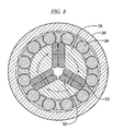
- FIG. 8 shows in general how rotary swaging works.
- head 26 is fixed.
- a motorized spindle 28 comprises slots for holding backers 30 and dies 32. The spindle passes the backers 30 over rollers 34 which causes the backers 30 to impact the dies 32 as the spindle 28 rotates.
- the backers 30 deliver a blow to the dies 32 which in turn impact the ring electrode 22 that is positioned within the dies 32, of the rotary swager.
- a backer 30 is between two roller positions, centrifugal forces cause it to move radially outwardly making it possible for the associated die 32 to open while the dies 32 are rotating around the ring electrode.
- the operation continues until the outer diameter of the ring electrode is reduced to about the outer diameter of the shaft of the tip section.
- the dies 32 which have a length of about 19.1 ⁇ m (0.75 inch) and are flared or tapered over the proximal half of the dies forming a cone-shaped entrance into the space within the dies.
- the distal- half of the dies forms a generally cylindrical space having a diameter about equal to the outer diameter to which the ring electrodes are swaged, i.e., the outer diameter of the shaft of the tip section.
- the cone-shaped entrance enables the diameter of the ring electrode to be reduced slowly, thus minimizing the risk of cracking or other damage to the ring electrode. It has been found that an angle of from about 2E to about 4E and particularly about 3E on each side is suitable for this purpose.
Landscapes
- Health & Medical Sciences (AREA)
- Engineering & Computer Science (AREA)
- Heart & Thoracic Surgery (AREA)
- Life Sciences & Earth Sciences (AREA)
- General Health & Medical Sciences (AREA)
- Public Health (AREA)
- Nuclear Medicine, Radiotherapy & Molecular Imaging (AREA)
- Surgery (AREA)
- Biomedical Technology (AREA)
- Animal Behavior & Ethology (AREA)
- Veterinary Medicine (AREA)
- Physics & Mathematics (AREA)
- Vascular Medicine (AREA)
- Cardiology (AREA)
- Plasma & Fusion (AREA)
- Otolaryngology (AREA)
- Radiology & Medical Imaging (AREA)
- Medical Informatics (AREA)
- Molecular Biology (AREA)
- Media Introduction/Drainage Providing Device (AREA)
- Surgical Instruments (AREA)
Claims (9)
- Verfahren zum Befestigen einer Ringelektrode an dem Schaft eines Katheterspitzenabschnittes (10), das aufweist:Bereitstellen eines Katheterspitzenabschnittes (10), der einen rohrförmigen Schaft mit wenigstens einem sich durch diesen erstreckenden Lumen (12) und wenigstens einem Austrittsloch (14), das sich von der Außenfläche des Schaftes des Katheterspitzenabschnittes (10) zu dem Lumen erstreckt, aufweist;Führen eines Elektrodenleitungsdrahtes (16) durch das Lumen (12) und aus dem Austrittsloch (14) heraus;Legen des Teiles des Elektrodenleitungsdrahtes (16), der sich aus dem Austrittsloch (14) erstreckt, mit wenigstens einer vollständigen Wicklung um den Umfang des Schaftes des Katheterspitzenabschnittes (10);Schieben einer Ringelektrode (22) über den Schaft des Katheterspitzenabschnittes (10) und Positionieren der Ringelektrode (22) direkt über dem um den Umfang gewickelten Elektrodenleitungsdraht (16); undVerformen der Ringelektrode (22), um ihren Durchmesser ausreichend zu verringern, so dass die Ringelektrode an dem Schaft des Katheterspitzenabschnittes (10) gesichert ist, wobei der Durchmesser der verformten Ringelektrode (22) ungefähr derselbe ist wie der Durchmesser des Schaftes des Katheterspitzenabschnittes (10),dadurch gekennzeichnet, dass die Ringelektrode (22) einen proximalen Bereich hat, der eine ausgestellte Schürze bildet.
- Verfahren nach Anspruch 1, bei dem der Elektrodenleitungsdraht (16) um den Umgang des Schaftes des Katheterspitzenabschnittes (10) ausreichend straff gelegt ist, so dass die äußerste Fläche des Elektrodenleitungsdrahtes im Allgemeinen mit der Außenfläche des Schaftes des Katheterspitzenabschnittes fluchtet.
- Verfahren nach Anspruch 1 oder Anspruch 2, bei dem der Elektrodenleitungsdraht (16) in wenigstens zwei Wicklungen um den Umfang des Schaftes des Spitzenabschnitts (10) gelegt ist.
- Verfahren nach einem der Ansprüche 1 bis 3, bei dem der Elektrodenleitungsdraht (16) um den Umfang des Schaftes des Spitzenabschnitts (10) gelegt ist und daran in einer Webeleinsteg-Anordnung gesichert ist.
- Verfahren nach einem der Ansprüche 1 bis 4, bei dem die Schürze (24) radial nach außen mit einem Winkel von ungefähr 4 bis ungefähr 8 Grad ausgestellt ist.
- Verfahren nach Anspruch 5, bei dem die Schürze (24) radial nach außen mit einem Winkel von ungefähr 6 Grad ausgestellt ist.
- Verfahren nach einem der Ansprüche 1 bis 6, bei dem der Elektrodenleitungsdraht (16) eine nicht leitende Beschichtung aufweist und die nicht leitende Beschichtung von dem Teil des Elektrodenleitungsdrahtes entfernt wird, der sich aus dem Austrittsloch erstreckt.
- Verfahren nach einem der Ansprüche 1 bis 7, bei dem der Schaft des Spitzenabschnitts (10) während des Legeschrittes ausreichend erwärmt wird, um das Material des Spitzenabschnittschaftes zu erweichen.
- Verfahren nach Anspruch 8, bei dem der Schaft des Spitzenabschnitts (10) aus Polyurethan hergestellt ist und während des Legeschrittes auf etwa 90 °C bis etwa 110 °C erhitzt wird.
Applications Claiming Priority (2)
| Application Number | Priority Date | Filing Date | Title |
|---|---|---|---|
| US706024 | 1976-07-21 | ||
| US10/706,024 US8136241B2 (en) | 2003-11-12 | 2003-11-12 | Method for making a low ohmic pressure-contact electrical connection between the ring electrode under surface and the lead wire |
Publications (2)
| Publication Number | Publication Date |
|---|---|
| EP1530981A1 EP1530981A1 (de) | 2005-05-18 |
| EP1530981B1 true EP1530981B1 (de) | 2008-12-10 |
Family
ID=34435621
Family Applications (1)
| Application Number | Title | Priority Date | Filing Date |
|---|---|---|---|
| EP04257012A Expired - Lifetime EP1530981B1 (de) | 2003-11-12 | 2004-11-11 | Verfahren zur Herstellung einer niederohmigen elektrischen Druckkontaktverbindung zwischen der Ringelektrode und dem Leiterdraht |
Country Status (4)
| Country | Link |
|---|---|
| US (1) | US8136241B2 (de) |
| EP (1) | EP1530981B1 (de) |
| JP (1) | JP5058435B2 (de) |
| DE (1) | DE602004018255D1 (de) |
Families Citing this family (6)
| Publication number | Priority date | Publication date | Assignee | Title |
|---|---|---|---|---|
| EP1835853A4 (de) * | 2005-01-12 | 2009-11-11 | Maquet Critical Care Ab | Elektrode zur messung physikalischer signale und herstellungsverfahren dafür |
| US9107673B2 (en) | 2005-12-23 | 2015-08-18 | Cathrx Ltd. | Irrigation catheter |
| US10046141B2 (en) * | 2008-12-30 | 2018-08-14 | Biosense Webster, Inc. | Deflectable sheath introducer |
| US8831749B2 (en) | 2012-10-31 | 2014-09-09 | Medtronic, Inc. | Implantable medical electrical lead conductors and construction methods |
| US9278187B2 (en) | 2013-03-13 | 2016-03-08 | Biosense Webster (Israel) Ltd. | Method for making a low OHMIC pressure-contact electrical connection between split ring electrode and lead wire |
| US20180228393A1 (en) * | 2017-02-15 | 2018-08-16 | Biosense Webster (Israel) Ltd. | Electrophysiologic device construction |
Family Cites Families (14)
| Publication number | Priority date | Publication date | Assignee | Title |
|---|---|---|---|---|
| US2286097A (en) * | 1938-10-29 | 1942-06-09 | Westinghouse Electric & Mfg Co | Terminal |
| US3717839A (en) * | 1971-01-08 | 1973-02-20 | Amp Inc | Threaded electrical connections |
| JPS57191306A (en) | 1981-05-20 | 1982-11-25 | Uni Charm Corp | Disposable diaper cover |
| US4592372A (en) * | 1984-05-22 | 1986-06-03 | Cordis Corporation | Pacing/sensing electrode sleeve and method of forming same |
| US4777955A (en) * | 1987-11-02 | 1988-10-18 | Cordis Corporation | Left ventricle mapping probe |
| US5383922A (en) * | 1993-03-15 | 1995-01-24 | Medtronic, Inc. | RF lead fixation and implantable lead |
| US6032061A (en) * | 1997-02-20 | 2000-02-29 | Boston Scientifc Corporation | Catheter carrying an electrode and methods of assembly |
| US5458629A (en) | 1994-02-18 | 1995-10-17 | Medtronic, Inc. | Implantable lead ring electrode and method of making |
| US5524337A (en) * | 1994-09-21 | 1996-06-11 | Ep Technologies, Inc. | Method of securing ring electrodes onto catheter |
| JPH09140803A (ja) * | 1995-11-21 | 1997-06-03 | Nippon Zeon Co Ltd | 電極カテーテルおよびその製造方法 |
| US6144870A (en) * | 1996-10-21 | 2000-11-07 | Procath Corporation | Catheter with improved electrodes and method of fabrication |
| US6324415B1 (en) * | 1997-07-30 | 2001-11-27 | Intermedics Inc. | Cardiac lead with minimized inside diameter of sleeve |
| US6171277B1 (en) | 1997-12-01 | 2001-01-09 | Cordis Webster, Inc. | Bi-directional control handle for steerable catheter |
| US6181971B1 (en) | 1998-12-09 | 2001-01-30 | Pacesetter, Inc. | Joining conductor cables and electrodes on a multi-lumen lead body |
-
2003
- 2003-11-12 US US10/706,024 patent/US8136241B2/en not_active Expired - Fee Related
-
2004
- 2004-11-11 DE DE602004018255T patent/DE602004018255D1/de not_active Expired - Lifetime
- 2004-11-11 JP JP2004327900A patent/JP5058435B2/ja not_active Expired - Fee Related
- 2004-11-11 EP EP04257012A patent/EP1530981B1/de not_active Expired - Lifetime
Also Published As
| Publication number | Publication date |
|---|---|
| DE602004018255D1 (de) | 2009-01-22 |
| JP5058435B2 (ja) | 2012-10-24 |
| US8136241B2 (en) | 2012-03-20 |
| US20050097737A1 (en) | 2005-05-12 |
| JP2005144175A (ja) | 2005-06-09 |
| EP1530981A1 (de) | 2005-05-18 |
Similar Documents
| Publication | Publication Date | Title |
|---|---|---|
| EP1127552B1 (de) | Ablationskatheter zur Erzeugung linearer Läsionen in Herzmuskelgewebe | |
| EP0037223B1 (de) | In den Körper implantierbarer Leiter mit einer Ringelektrode und Verfahren zu seiner Herstellung | |
| US6144870A (en) | Catheter with improved electrodes and method of fabrication | |
| US4461300A (en) | Bone and tissue healing device including a special electrode assembly and method | |
| US4280511A (en) | Ring electrode for pacing lead and process of making same | |
| EP1043042B1 (de) | Klemmvorrichtung zum Festklemmen einer Leitung | |
| US4614395A (en) | Quick connector to medical electrical lead | |
| CN104042336B (zh) | 在裂环电极与引线间形成低欧姆式压力接触电连接的方法 | |
| US10279144B2 (en) | Method of manufacturing a catheter sheath | |
| EP0442444A2 (de) | Implantierbare Elektrode und Herstellungsverfahren | |
| WO2001074443A1 (en) | Implantable stimulation lead and method of manufacture | |
| US8219209B2 (en) | Implantable medical lead having reduced dimension tubing transition | |
| EP1128869B1 (de) | Entfernbare implantierbare medizinische leitung | |
| EP1530981B1 (de) | Verfahren zur Herstellung einer niederohmigen elektrischen Druckkontaktverbindung zwischen der Ringelektrode und dem Leiterdraht | |
| US20070079511A1 (en) | Device for slitting an introducer for a pacemaker lead | |
| US8204570B2 (en) | Electrode for physiological signal measurements and method for making same | |
| US4413636A (en) | Catheter | |
| US20130245732A1 (en) | Lead header and manufacture thereof | |
| US5347708A (en) | Method for fabrication of implantable electrode | |
| US9949647B2 (en) | Sensor and guide wire assembly | |
| US10933247B2 (en) | Lead with integrated features to facilitate extraction and associated methods of extraction | |
| JP6313034B2 (ja) | カテーテルの製造方法およびカテーテル | |
| CN116348048A (zh) | 具有改进的其元件附接的细长装置 | |
| CN217563007U (zh) | 多导通弹性电极 | |
| US20180368728A1 (en) | Electrode catheter assembly and method for the manufacture thereof |
Legal Events
| Date | Code | Title | Description |
|---|---|---|---|
| PUAI | Public reference made under article 153(3) epc to a published international application that has entered the european phase |
Free format text: ORIGINAL CODE: 0009012 |
|
| AK | Designated contracting states |
Kind code of ref document: A1 Designated state(s): AT BE BG CH CY CZ DE DK EE ES FI FR GB GR HU IE IS IT LI LU MC NL PL PT RO SE SI SK TR |
|
| AX | Request for extension of the european patent |
Extension state: AL HR LT LV MK YU |
|
| 17P | Request for examination filed |
Effective date: 20051028 |
|
| AKX | Designation fees paid |
Designated state(s): DE GB NL |
|
| 17Q | First examination report despatched |
Effective date: 20060918 |
|
| GRAP | Despatch of communication of intention to grant a patent |
Free format text: ORIGINAL CODE: EPIDOSNIGR1 |
|
| GRAS | Grant fee paid |
Free format text: ORIGINAL CODE: EPIDOSNIGR3 |
|
| GRAA | (expected) grant |
Free format text: ORIGINAL CODE: 0009210 |
|
| AK | Designated contracting states |
Kind code of ref document: B1 Designated state(s): DE GB NL |
|
| REG | Reference to a national code |
Ref country code: GB Ref legal event code: FG4D |
|
| REF | Corresponds to: |
Ref document number: 602004018255 Country of ref document: DE Date of ref document: 20090122 Kind code of ref document: P |
|
| PLBE | No opposition filed within time limit |
Free format text: ORIGINAL CODE: 0009261 |
|
| STAA | Information on the status of an ep patent application or granted ep patent |
Free format text: STATUS: NO OPPOSITION FILED WITHIN TIME LIMIT |
|
| 26N | No opposition filed |
Effective date: 20090911 |
|
| PGFP | Annual fee paid to national office [announced via postgrant information from national office to epo] |
Ref country code: GB Payment date: 20220930 Year of fee payment: 19 |
|
| PGFP | Annual fee paid to national office [announced via postgrant information from national office to epo] |
Ref country code: NL Payment date: 20221019 Year of fee payment: 19 |
|
| PGFP | Annual fee paid to national office [announced via postgrant information from national office to epo] |
Ref country code: DE Payment date: 20220621 Year of fee payment: 19 |
|
| REG | Reference to a national code |
Ref country code: DE Ref legal event code: R119 Ref document number: 602004018255 Country of ref document: DE |
|
| REG | Reference to a national code |
Ref country code: NL Ref legal event code: MM Effective date: 20231201 |
|
| GBPC | Gb: european patent ceased through non-payment of renewal fee |
Effective date: 20231111 |
|
| PG25 | Lapsed in a contracting state [announced via postgrant information from national office to epo] |
Ref country code: NL Free format text: LAPSE BECAUSE OF NON-PAYMENT OF DUE FEES Effective date: 20231201 |
|
| PG25 | Lapsed in a contracting state [announced via postgrant information from national office to epo] |
Ref country code: NL Free format text: LAPSE BECAUSE OF NON-PAYMENT OF DUE FEES Effective date: 20231201 |
|
| PG25 | Lapsed in a contracting state [announced via postgrant information from national office to epo] |
Ref country code: DE Free format text: LAPSE BECAUSE OF NON-PAYMENT OF DUE FEES Effective date: 20240601 |
|
| PG25 | Lapsed in a contracting state [announced via postgrant information from national office to epo] |
Ref country code: GB Free format text: LAPSE BECAUSE OF NON-PAYMENT OF DUE FEES Effective date: 20231111 |
|
| PG25 | Lapsed in a contracting state [announced via postgrant information from national office to epo] |
Ref country code: GB Free format text: LAPSE BECAUSE OF NON-PAYMENT OF DUE FEES Effective date: 20231111 Ref country code: DE Free format text: LAPSE BECAUSE OF NON-PAYMENT OF DUE FEES Effective date: 20240601 |