EP1530915B1 - Schuh - Google Patents
Schuh Download PDFInfo
- Publication number
- EP1530915B1 EP1530915B1 EP04256550A EP04256550A EP1530915B1 EP 1530915 B1 EP1530915 B1 EP 1530915B1 EP 04256550 A EP04256550 A EP 04256550A EP 04256550 A EP04256550 A EP 04256550A EP 1530915 B1 EP1530915 B1 EP 1530915B1
- Authority
- EP
- European Patent Office
- Prior art keywords
- yoke
- shaped member
- footwear
- item
- heel
- Prior art date
- Legal status (The legal status is an assumption and is not a legal conclusion. Google has not performed a legal analysis and makes no representation as to the accuracy of the status listed.)
- Not-in-force
Links
Images


Classifications
-
- A—HUMAN NECESSITIES
- A43—FOOTWEAR
- A43B—CHARACTERISTIC FEATURES OF FOOTWEAR; PARTS OF FOOTWEAR
- A43B3/00—Footwear characterised by the shape or the use
- A43B3/24—Collapsible or convertible
- A43B3/246—Collapsible or convertible characterised by the sole
-
- A—HUMAN NECESSITIES
- A43—FOOTWEAR
- A43B—CHARACTERISTIC FEATURES OF FOOTWEAR; PARTS OF FOOTWEAR
- A43B3/00—Footwear characterised by the shape or the use
- A43B3/24—Collapsible or convertible
-
- A—HUMAN NECESSITIES
- A43—FOOTWEAR
- A43B—CHARACTERISTIC FEATURES OF FOOTWEAR; PARTS OF FOOTWEAR
- A43B5/00—Footwear for sporting purposes
- A43B5/16—Skating boots
-
- A—HUMAN NECESSITIES
- A63—SPORTS; GAMES; AMUSEMENTS
- A63C—SKATES; SKIS; ROLLER SKATES; DESIGN OR LAYOUT OF COURTS, RINKS OR THE LIKE
- A63C17/00—Roller skates; Skate-boards
- A63C17/008—Roller skates; Skate-boards with retractable wheel, i.e. movable relative to the chassis out of contact from surface
-
- A—HUMAN NECESSITIES
- A63—SPORTS; GAMES; AMUSEMENTS
- A63C—SKATES; SKIS; ROLLER SKATES; DESIGN OR LAYOUT OF COURTS, RINKS OR THE LIKE
- A63C17/00—Roller skates; Skate-boards
- A63C17/04—Roller skates; Skate-boards with wheels arranged otherwise than in two pairs
- A63C17/06—Roller skates; Skate-boards with wheels arranged otherwise than in two pairs single-track type
- A63C17/08—Roller skates; Skate-boards with wheels arranged otherwise than in two pairs single-track type single-wheel type with single axis
-
- A—HUMAN NECESSITIES
- A63—SPORTS; GAMES; AMUSEMENTS
- A63C—SKATES; SKIS; ROLLER SKATES; DESIGN OR LAYOUT OF COURTS, RINKS OR THE LIKE
- A63C17/00—Roller skates; Skate-boards
- A63C17/20—Roller skates; Skate-boards with fixable wheels permitting the skates to be used for walking
Definitions
- the present invention relates to an item of footwear, and is particularly concerned with a wheeled shoe for recreation.
- a wheel may be housed in the heel of a specially adapted shoe.
- the wheel must be inserted and fitted into the heel of the shoe prior to use as a wheeled shoe for recreation, and the wheel must be removed entirely from the shoe when not in such use.
- the user is provided with a removal tool to remove the wheel from the shoe.
- the shoe is converted from a first state, whereby the shoe in combination with the wheel facilitates the foot of a wearer to roll across a road surface or similar, to a second state, whereby the shoe is made suitable for walking as would be considered normal.
- a heel plug is provided to replace the wheel when the shoe is converted into the second state.
- the housing which is vacated by the wheel should be plugged using a heel plug.
- the heel plug or the wheel should be available if the wearer wishes to change the configuration of the shoe.
- US2003/132586 relates to a multifunctional shoe for walking and skating with a single roller with the features of the preamble of claims 1 and 6.
- An aim of the present invention is to provide a wheeled shoe in which the wearer does not have to remove entirely the wheel from the shoe to convert the shoe to a state suitable for normal walking or running.
- the present invention provides a item of footwear provided with rolling means to enable the item of footwear to roll over a surface when the rolling means is in a first active position, the item of footwear, further comprising a heel and retracting means for retracting the rolling means to a second latent position, thereby disabling the rolling means and preventing the item of footwear from rolling over a surface with the features of claims 1 and 6.
- the wearer may use the item of footwear both for normal activities, such as walking and running, and recreational activities where footwear that rolls over a road surface or similar is required. Moreover, it is not necessary to remove and replace the rolling means from the item of footwear to change the function of the item of footwear from a normal mode to a recreational mode.
- the rolling means comprises a cylindrical roller defining a longitudinal axis about which the roller can rotate, and the rolling means is attached to the retracting means by an axle, the axle being received in a pair of angled slots formed in the yoke-shaped member.
- the slidable yoke-shaped member may include two elongate arms.
- the rolling means may be positioned in the first active state when positioned in lower portions of the angled slots; or, in the second latent state, when positioned in higher portions of the angled slots.
- the angled slots define two detent notches to retain the rolling means in the first active position and the second latent position respectively. In this way, the rolling means is held in position until a suitable force great enough to overcome the resistance of the detent notches is applied.
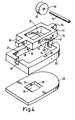
- a shoe 10 comprises three main sections, namely an upper 12, a sole 14, and a heel 16, where the heel is joined to the underside of the sole at a rear end.
- the front portion of the heel 16 has a straight vertical face 24 facing forwards away from the heel.
- the rear portion of the heel 16 has a curved face 26 facing rearwards.
- the heel 16 is split by two separate horizontal planes into three portions, namely a top portion 18, a mid portion 20 and a bottom portion 22.
- the mid portion 20 is thicker than the top portion 18, and the top portion is thicker than the bottom portion 22.
- the upper face of the top portion 18 is joined to the underside of the sole 14.
- the top portion 18 has a slot 28, the slot has an arcuate inner face shaped to complement a roller 50.
- the slot 28 opens on the bottom face of the top portion 18.
- the mid portion 20 is joined to the underside of the top portion 18 such that, when the mid portion is joined to the top portion, the join therebetween is barely noticeable.
- the mid portion 20 has a central vertical hole 21 of rectangular cross-section, the hole extending through the full height of the mid portion.
- the mid portion 20 further defines a pair of opposing slots 30 and a pair of opposing channels 32. An axis through the pair of slots 30 is perpendicular to an axis through the pair of channels 32.
- the channels 32 extend in the longitudinal direction with respect to the direction of forward movement of the shoe 10.
- the channels 32 and the slots 30 are formed in the upper part of the mid portion 20 such that, when the mid portion 20 is joined to the top portion 22, the slots 30 and the channels 32 are closed by the top portion 18.
- a slide yoke 34 is provided to fit into the hole of the mid portion 20.
- the periphery of the slide yoke 34 is substantially rectangular.
- the width of the slide yoke 34 is marginally narrower than the width of the hole 21 of the mid portion 20.
- the length of the slide yoke 34 is substantially shorter than length of the hole 21. This is to facilitate the slide yoke 34 to move freely forwards and backwards within the hole 21 in a direction following the longitudinal axis of the shoe 10.
- the slide yoke 34 has a central vertical hole 35 of rectangular cross-section.
- the slide yoke 34 has two arms 36 positioned on the upper part of its front face 38 and its rear face 40.
- the arms 36 are of a shape complementary to the shape of the channels 32 of the mid portion 20 such that, when the slide yoke 34 is located in the mid portion, the arms fit flush into the channels 32 and the slide yoke fits flush into the mid portion 20.
- the arms 36 are of a length such that at least one of the arms always extends outwardly from the mid portion 20.
- the slide yoke 34 is formed with a pair of angled slots 42 in opposite sides thereof. The angled slots 42 are located substantially midway along the slide yoke 34.
- a front end 44 of each slot 42 is higher than a rear end 46.
- a sloping portion 48 joins the front end 44 and the rear end 46.
- a detent notch 43 is located at the front end 44 of each angled slot.
- a further detent notch 45 is located at the rear end 46 of each angled slot.
- the slide yoke 34 is manufactured from a nylon type material or similar. In this way the angled slots 42 may elastically deform at the detent notches 43, 45.
- a cylindrical roller 50 is provided with a central hole 52 for receiving a roller pin 54.
- the roller pin 54 is cylindrical, and is of sufficient diameter to be inserted through the central hole 52 of the roller 50.
- the roller pin 54 is of sufficient length to span the gap between the pair of opposing slots 30 of the mid portion 20.
- the roller 52 is retained in the slide yoke 34 by the roller pin 54. With the roller 50 positioned between the angled slots 42, the roller pin 54 is inserted through the first angled slot 42, the central hole 52 and the second angled slot 42, such that the roller pin protrudes equally from both ends of the roller.
- the slide yoke 34 is inserted into the mid portion 34 and the roller pin 54 and roller 50 are locked into place.
- the bottom portion 22 is joined to the underside of the top portion 18 such that the join therebetween is barely noticeable.
- the bottom portion 32 has a centrally-located tapered hole 55 with a larger opening 56 on the top surface of the bottom portion, and a smaller opening 58 on the bottom surface of the bottom portion.
- the tapered hole 55 is of a shape complementary to the shape of the roller 50.
- the roller 50 may be positioned in a raised state 60 or in a lowered state 62 (see Figure 1 and Figure 2b ) by the slide yoke 34 held captive in the heel 16.
- the slide yoke 34 may be positioned in a forward state by the wearer pushing the protruding arm 36 at the rear of the heel 16 forwards. This causes the roller pin 54 to move from the higher position 44 to the lower position 46 while remaining in the slot 30. Some force is required to free the roller pin 54 from the front end 44 of the angled slots 42 as a result of the detent notch 43. A similar force is required to engage the roller pin 54 in the lower end of the angled slots 42 as a result of a second detent notch 45. In this state with the roller 50 lowered, the wearer can roll over a surface.
- the slide yoke 34 may be positioned in a rearward state by pushing the protruding arm 36 at the front of the heel 16 back into the heel.
- the angled slots 42 of the slide yoke 34 are pushed rearward and the roller pin 54, held horizontally captive in the slots 30, follows the angled slot 42 to a raised position where it is locked into place by the detent slot 43.
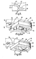
- a recess 68 in the sole 14 is shaped complementary to the upper face of the upper portion 18.
- the recess 68 is deeper than the height of the upper portion 18.
- the upper face of the upper portion 18 is joined to the sole 14 within the recess 68.
- the whole of the upper portion 18 is received by the recess 68 such that the mid portion 20 contacts with the front edge 69 of the recess.
- a groove 70 is defined by the sole 14 and extends along its length in a forwards direction from the recess 68.
- the mid portion 20 defines a channel 32 on the upper half of its front side, such that the channel 32 is facing the groove 70.
- the channel 32 is not defined in the rear of the mid portion 20 as was the case in the first embodiment.
- the slide yoke 34 has one arm 72 positioned on the upper part of its front face 38 (not visible in Figure 6 ).
- the arm 72 is of a shape complementary to the shape of the channel 32 and the groove 70, such that the arm fits flush into the channel and extends therethrough and fits flush into the groove.
- the arm 72 is of a length such that, when the slide yoke 34 is located at the rear of the mid portion 20, the arm protrudes through the channel 32 and into the groove 70.
- the arm 72 defines a member 74 which protrudes below the groove 70 such that a user may move the position of the arm.
- the slide yoke 34 may be positioned in a forward state by the wearer pushing the member 74 on the arm 72 forwards.
- the slide yoke 34 may be positioned in a rearward state by pushing the member 74 on the arm 72 rearwards.
Claims (7)
- Schuh (10) mit einem einen Rollvorgang ermöglichenden Mittel (50), damit der Schuh über eine Fläche rollen kann, wenn das den Rollvorgang ermöglichende Mittel sich in einer ersten aktiven Position befindet, wobei der Schuh weiterhin einen Absatz (16) und zurückziehende Mittel (34, 42, 54) zum Zurückziehen des den Rollvorgang erlaubenden Mittels in eine zweite unwirksame Position aufweist, wodurch das die Rollbewegung bewirkende Mittel unwirksam gemacht und der Schuh daran gehindert wird, über eine Fläche zu rollen, dadurch gekennzeichnet, dass das zurückziehende Mittel ein gleitbares jochförmiges Element (34) aufweist, welches innerhalb einer Öffnung (21) gleitbar angebracht ist, die im Absatz für die Bewegung in Längsrichtung des Schuhes vorgesehen ist, und das die Rollbewegung ermöglichende Mittel innerhalb einer Öffnung (35) angebracht ist, welche in den jochförmigen Element zwecks in Längsrichtung erfolgender Bewegung relativ dazu vorgesehen ist, und das jochförmige Element mit einem Arm (36) versehen ist, welcher durch eine im Absatz befindliche Öffnung (32) vorsteht und durch den Benutzer erfassbar ist, um das die Rollbewegung ermöglichende Mittel zwischen seiner aktiven und seiner Warteposition zu bewegen, und das die Rollbewegung ermöglichende Mittel an dem die Rückziehbewegung ermöglichende Mittel durch eine Achse (54) angebracht ist, die von einem Paar gewinkelter Schlitze (42) aufgenommen wird, die an dem jochförmigen Element (34) angebracht sind, und der Absatz mit zwei im wesentlichen vertikalen Schlitzen (30) versehen ist, die zu den Schlitzen in dem jochförmigen Element derart ausgerichtet sind, dass die Achse sich durch die Schlitze des jochförmigen Elementes in die entsprechenden Schlitze des Absatzes erstreckt, so dass die Bewegung des jochförmigen Elementes eine Bewegung der Achse bewirkt, in deren Verlauf sie der Bahn der geneigten Schlitze folgt, wodurch ein Anheben und Absenken des die Rollbewegung ermöglichenden Mittels bewirkt wird.
- Schuh nach Anspruch 1, bei welchem das die Rollbewegung bewirkende Mittel eine zylindrische Rolle (50) umfasst, welche eine Längsachse definiert, um welche die Rolle rotierbar ist.
- Schuh nach Anspruch 1 oder 2, bei welchem der Arm (36) von dem vorderen Teil des Absatzes (16) vorsteht.
- Schuh nach einem der Ansprüche 1 - 3, bei welchem die gewinkelten Schlitze (42) zwei Rastaussparungen (43, 46) begrenzen, um das die Rollbewegung ermöglichende Mittel jeweils in der ersten aktiven Position und der zweiten Warteposition zu halten.
- Schuh nach einem der Ansprüche 1 - 4, bei welchem die Öffnung (21) im Absatz (16) im wesentlichen rechteckig ist und das jochförmige Element (34) eine äußere Breite aufweist, die geringfügig kleiner ist als die Breite der Öffnung (21), und die Länge dieser Öffnung (21) größer ist als die Länge des jochförmigen Elementes (34), so dass das jochförmige Element innerhalb des Absatzes in Längsrichtung bewegbar ist.
- Schuh (10) mit einem einen Rollvorgang ermöglichenden Mittel (50), damit der Schuh über deine Fläche rollbar ist, wenn das die Rollbewegung ermöglichende Mittel in einer ersten aktiven Position sich befindet, wobei der Schuh weiterhin einen Absatz (16) und zurückziehende Mittel (34, 42, 54) zum Zurückziehen des die Rollbewegung ermöglichenden Mittels in die zweite Warteposition aufweist, wodurch das die Rollbewegung ermöglichende Mittel unwirksam ist und der Schuh daran gehindert ist, über eine Fläche zu rollen, dadurch gekennzeichnet, dass das zurückziehende Mittel ein gleitbares jochförmiges Element (34) aufweist, das gleitbar in einer Öffnung (21) angebracht ist, welche im Absatz zwecks Bewegung in der Längsrichtung des Schuhs vorgesehen ist, und das die Rollbewegung ermöglichende Mittel innerhalb einer Öffnung (35) angebracht ist, welche in dem jochförmigen Element ausgebildet ist, um eine in Längsrichtung erfolgende Bewegung relativ dazu zu ermöglichen, und das jochförmige Element mit einem Arm (36) versehen ist, der durch eine Öffnung (32) im Absatz vorsteht, damit ein Benutzer ihn ergreifen kann, um das die Rollbewegung ermöglichende Mittel zwischen seiner aktiven Position und seiner Warteposition zu bewegen, und das jochförmige Element den Umfang der die Rollbewegung ermöglichenden Mittel umgibt, wobei sich das die Rollbewegung ermöglichende Mittel oberhalb und unterhalb des jochförmigen Elementes an der Stelle erstreckt, an welcher die Öffnung durch das jochförmige Element vorhanden ist.
- Schuh nach Anspruch 6, bei welchem das jochförmige Element (34) Teile aufweist, welche direkt vor und hinter der Peripherie des den Rollvorgang ermöglichenden Mittels (50) befinden, das sich oberhalb und unterhalb des jochförmigen Elementes an der Stelle erstreckt, an welcher sich die Öffnung durch das jochförmige Element befindet.
Applications Claiming Priority (4)
| Application Number | Priority Date | Filing Date | Title |
|---|---|---|---|
| GB0326400 | 2003-11-12 | ||
| GBGB0326400.9A GB0326400D0 (en) | 2003-11-12 | 2003-11-12 | An item fo footwear |
| GB0329335A GB2407993B (en) | 2003-11-12 | 2003-12-18 | An item of footwear |
| GB0329335 | 2003-12-18 |
Publications (2)
| Publication Number | Publication Date |
|---|---|
| EP1530915A1 EP1530915A1 (de) | 2005-05-18 |
| EP1530915B1 true EP1530915B1 (de) | 2009-06-10 |
Family
ID=34436837
Family Applications (1)
| Application Number | Title | Priority Date | Filing Date |
|---|---|---|---|
| EP04256550A Not-in-force EP1530915B1 (de) | 2003-11-12 | 2004-10-22 | Schuh |
Country Status (3)
| Country | Link |
|---|---|
| US (1) | US7195251B2 (de) |
| EP (1) | EP1530915B1 (de) |
| JP (1) | JP2005144177A (de) |
Cited By (2)
| Publication number | Priority date | Publication date | Assignee | Title |
|---|---|---|---|---|
| US8480095B2 (en) | 1999-04-01 | 2013-07-09 | Heeling Sports Limited | Heeling apparatus wheel assembly |
| WO2017158410A1 (ru) * | 2016-03-14 | 2017-09-21 | Сергей ЛЕВКИН | Обувь с электроприводом |
Families Citing this family (17)
| Publication number | Priority date | Publication date | Assignee | Title |
|---|---|---|---|---|
| US7661205B2 (en) * | 1998-03-26 | 2010-02-16 | Johnson Gregory G | Automated tightening shoe |
| US8006795B2 (en) * | 2004-05-04 | 2011-08-30 | Yonatan Manor | Device and method for regaining balance |
| ES2545261T3 (es) * | 2004-08-04 | 2015-09-09 | Heeling Sports Limited | Aparato y procedimiento de transporte motorizado |
| US20070252351A1 (en) * | 2006-05-01 | 2007-11-01 | R.O.C. Company Inc. | Wheeled footwear |
| FI119717B (fi) * | 2006-05-04 | 2009-02-27 | Polar Electro Oy | Käyttäjäkohtainen suoritemittari, menetelmä ja tietokoneohjelmistotuote |
| US7850175B2 (en) * | 2007-03-29 | 2010-12-14 | Wegener Andreas C | Footwear with adjustable wheel assembly |
| US7735840B2 (en) * | 2007-08-02 | 2010-06-15 | Bbc International Llc | Roller shoe |
| US20090058021A1 (en) * | 2007-08-29 | 2009-03-05 | E-Dich International Co., Ltd. | Sliding apparatus for roller skate shoe |
| KR100854575B1 (ko) * | 2008-03-20 | 2008-08-26 | 문덕기 | 롤러 상하작동장치 |
| WO2011031885A1 (en) * | 2009-09-09 | 2011-03-17 | Heeling Sports Limited | Wheeled platform apparatus and method for use with wheeled footwear |
| JP5312401B2 (ja) * | 2010-05-28 | 2013-10-09 | 株式会社コマリヨー | ローラーシューズ |
| US8904673B2 (en) | 2011-08-18 | 2014-12-09 | Palidium, Inc. | Automated tightening shoe |
| US8904672B1 (en) | 2011-08-18 | 2014-12-09 | Palidium Inc. | Automated tightening shoe |
| US10945485B2 (en) | 2012-08-03 | 2021-03-16 | Heeling Sports Limited | Heeling apparatus |
| US20150096197A1 (en) * | 2013-10-06 | 2015-04-09 | Elsa Salinas | Shoe With Retractable Heel |
| WO2016178450A1 (ko) * | 2015-05-07 | 2016-11-10 | 이영주 | 신발용 롤러 모듈 및 이를 갖는 바퀴 신발 |
| EP4232170A1 (de) | 2020-10-21 | 2023-08-30 | Shift Robotics, Inc. | Motorgetriebene schuhvorrichtungsradkonfiguration mit kombiniertem translations- und drehscharniermechanismus und integrierter getriebezerkleinerungsanordnung |
Family Cites Families (17)
| Publication number | Priority date | Publication date | Assignee | Title |
|---|---|---|---|---|
| JPS6099202A (ja) * | 1983-11-02 | 1985-06-03 | 東 隆雄 | スパイクシユーズ |
| JPS6120504A (ja) * | 1984-07-07 | 1986-01-29 | 川上 利男 | スパイク機構を内蔵したハイヒ−ル |
| JPH0393641A (ja) * | 1989-09-07 | 1991-04-18 | Sumitomo Electric Ind Ltd | 光ファイバ用ガラス母材の製造方法 |
| JP2560681B2 (ja) * | 1992-09-18 | 1996-12-04 | セイコープレシジョン株式会社 | 印字モードを切換え可能なワイヤドットプリンタ |
| US5398970A (en) * | 1993-07-28 | 1995-03-21 | Tucky; Edward W. | Shoes for walking and roller skating |
| FR2715320B1 (fr) * | 1994-01-26 | 1996-05-24 | Frederic Fichepain | Semelle de chaussure dotée de roulettes rétractables. |
| US5586777A (en) * | 1995-06-05 | 1996-12-24 | Wolf; David | In line skate with dynamically adjustable wheels |
| FR2757412B1 (fr) * | 1996-12-19 | 1999-02-26 | Allouche Claude | Chaussure a roulettes retractables vers une position de non-utilisation |
| US5785327A (en) * | 1997-06-20 | 1998-07-28 | Gallant; Raymond J. | Skates having retractable rollers |
| US6120039A (en) * | 1999-08-16 | 2000-09-19 | Clementi; Fred | Walking and in-line skate shoe |
| WO2002007552A1 (en) * | 2000-07-21 | 2002-01-31 | Lee Hong Kil | Roller blade shoes |
| US6450508B1 (en) * | 2001-03-02 | 2002-09-17 | Wei-Yen Chu | Shoe for skating and walking |
| US6394468B1 (en) * | 2001-05-02 | 2002-05-28 | Kuo-Pin Chiang | Dual-purpose shoe |
| US6629698B2 (en) * | 2001-10-03 | 2003-10-07 | Wei-Yen Chu | Multifunctional shoe |
| CN2520912Y (zh) * | 2002-01-16 | 2002-11-20 | 东莞上安鸿运动器材厂 | 独轮步行滑行多功能鞋 |
| US6913270B2 (en) * | 2003-06-16 | 2005-07-05 | Kuo-Hua Wang | Roller skate shoe |
| DE20315227U1 (de) * | 2003-10-02 | 2004-01-08 | Chen, Ching-Long, Neihu Chiu | Rollenmechanismus für Sport- und Rollschuhe |
-
2004
- 2004-10-22 EP EP04256550A patent/EP1530915B1/de not_active Not-in-force
- 2004-11-08 US US10/983,773 patent/US7195251B2/en not_active Expired - Fee Related
- 2004-11-12 JP JP2004328956A patent/JP2005144177A/ja active Pending
Cited By (3)
| Publication number | Priority date | Publication date | Assignee | Title |
|---|---|---|---|---|
| US8480095B2 (en) | 1999-04-01 | 2013-07-09 | Heeling Sports Limited | Heeling apparatus wheel assembly |
| US9242169B2 (en) | 1999-04-01 | 2016-01-26 | Heeling Sports Limited | Heeling apparatus |
| WO2017158410A1 (ru) * | 2016-03-14 | 2017-09-21 | Сергей ЛЕВКИН | Обувь с электроприводом |
Also Published As
| Publication number | Publication date |
|---|---|
| US7195251B2 (en) | 2007-03-27 |
| JP2005144177A (ja) | 2005-06-09 |
| EP1530915A1 (de) | 2005-05-18 |
| US20050121862A1 (en) | 2005-06-09 |
Similar Documents
| Publication | Publication Date | Title |
|---|---|---|
| EP1530915B1 (de) | Schuh | |
| US5644857A (en) | Golf shoes with interchangaeable soles | |
| KR101835053B1 (ko) | 착용 가능한 장치 | |
| US5067736A (en) | Slotted brake for in-line roller skate | |
| CA2460018A1 (en) | Improved expandable shoe and shoe assemblies | |
| CA2169742A1 (en) | Athletic shoe with improved sole | |
| CA2351236A1 (en) | Skate | |
| US5806860A (en) | Frame for skates with aligned wheels | |
| US8015664B2 (en) | Twin-wheel caster | |
| EP0997169A2 (de) | Rollschuhe | |
| US5890722A (en) | Roller skate lock | |
| US20040036237A1 (en) | Convertible shoe | |
| US6394468B1 (en) | Dual-purpose shoe | |
| KR101772843B1 (ko) | 승하강식 인라인 롤러스케이트 슈즈 | |
| GB2407993A (en) | An item of footwear with retractable rolling means | |
| US5954348A (en) | Roller skate with wheel control mechanism | |
| US5820138A (en) | Convertible in-line roller skates | |
| KR100358602B1 (ko) | 롤러 블레이드가 내장된 신발 | |
| KR200211686Y1 (ko) | 롤러 블레이드가 내장된 신발 | |
| US20020153678A1 (en) | Position-adjustable brake unit for a dual-purpose roller skate | |
| KR100295358B1 (ko) | 낚시화겸용등산화 | |
| KR100518113B1 (ko) | 바퀴 장착형 신발 | |
| KR200330176Y1 (ko) | 힐링 슈즈 | |
| KR200266160Y1 (ko) | 푸시 스쿠터용 스노우 보드 | |
| KR200192507Y1 (ko) | 미끄럼방지용 신발 |
Legal Events
| Date | Code | Title | Description |
|---|---|---|---|
| PUAI | Public reference made under article 153(3) epc to a published international application that has entered the european phase |
Free format text: ORIGINAL CODE: 0009012 |
|
| AK | Designated contracting states |
Kind code of ref document: A1 Designated state(s): AT BE BG CH CY CZ DE DK EE ES FI FR GB GR HU IE IT LI LU MC NL PL PT RO SE SI SK TR |
|
| AX | Request for extension of the european patent |
Extension state: AL HR LT LV MK |
|
| REG | Reference to a national code |
Ref country code: HK Ref legal event code: DE Ref document number: 1076017 Country of ref document: HK |
|
| 17P | Request for examination filed |
Effective date: 20051117 |
|
| AKX | Designation fees paid |
Designated state(s): AT BE BG CH CY CZ DE DK EE ES FI FR GB GR HU IE IT LI LU MC NL PL PT RO SE SI SK TR |
|
| RAP1 | Party data changed (applicant data changed or rights of an application transferred) |
Owner name: AUTOMATION CONVEYORS (HOLDINGS) LIMITED |
|
| GRAP | Despatch of communication of intention to grant a patent |
Free format text: ORIGINAL CODE: EPIDOSNIGR1 |
|
| GRAS | Grant fee paid |
Free format text: ORIGINAL CODE: EPIDOSNIGR3 |
|
| GRAA | (expected) grant |
Free format text: ORIGINAL CODE: 0009210 |
|
| AK | Designated contracting states |
Kind code of ref document: B1 Designated state(s): AT BE BG CH CY CZ DE DK EE ES FI FR GB GR HU IE IT LI LU MC NL PL PT RO SE SI SK TR |
|
| REG | Reference to a national code |
Ref country code: GB Ref legal event code: FG4D |
|
| REG | Reference to a national code |
Ref country code: CH Ref legal event code: EP |
|
| REG | Reference to a national code |
Ref country code: IE Ref legal event code: FG4D |
|
| REF | Corresponds to: |
Ref document number: 602004021463 Country of ref document: DE Date of ref document: 20090723 Kind code of ref document: P |
|
| PG25 | Lapsed in a contracting state [announced via postgrant information from national office to epo] |
Ref country code: AT Free format text: LAPSE BECAUSE OF FAILURE TO SUBMIT A TRANSLATION OF THE DESCRIPTION OR TO PAY THE FEE WITHIN THE PRESCRIBED TIME-LIMIT Effective date: 20090610 Ref country code: FI Free format text: LAPSE BECAUSE OF FAILURE TO SUBMIT A TRANSLATION OF THE DESCRIPTION OR TO PAY THE FEE WITHIN THE PRESCRIBED TIME-LIMIT Effective date: 20090610 |
|
| NLV1 | Nl: lapsed or annulled due to failure to fulfill the requirements of art. 29p and 29m of the patents act | ||
| PG25 | Lapsed in a contracting state [announced via postgrant information from national office to epo] |
Ref country code: SE Free format text: LAPSE BECAUSE OF FAILURE TO SUBMIT A TRANSLATION OF THE DESCRIPTION OR TO PAY THE FEE WITHIN THE PRESCRIBED TIME-LIMIT Effective date: 20090910 Ref country code: SI Free format text: LAPSE BECAUSE OF FAILURE TO SUBMIT A TRANSLATION OF THE DESCRIPTION OR TO PAY THE FEE WITHIN THE PRESCRIBED TIME-LIMIT Effective date: 20090610 Ref country code: NL Free format text: LAPSE BECAUSE OF FAILURE TO SUBMIT A TRANSLATION OF THE DESCRIPTION OR TO PAY THE FEE WITHIN THE PRESCRIBED TIME-LIMIT Effective date: 20090610 Ref country code: PL Free format text: LAPSE BECAUSE OF FAILURE TO SUBMIT A TRANSLATION OF THE DESCRIPTION OR TO PAY THE FEE WITHIN THE PRESCRIBED TIME-LIMIT Effective date: 20090610 |
|
| PG25 | Lapsed in a contracting state [announced via postgrant information from national office to epo] |
Ref country code: CZ Free format text: LAPSE BECAUSE OF FAILURE TO SUBMIT A TRANSLATION OF THE DESCRIPTION OR TO PAY THE FEE WITHIN THE PRESCRIBED TIME-LIMIT Effective date: 20090610 Ref country code: ES Free format text: LAPSE BECAUSE OF FAILURE TO SUBMIT A TRANSLATION OF THE DESCRIPTION OR TO PAY THE FEE WITHIN THE PRESCRIBED TIME-LIMIT Effective date: 20090921 Ref country code: EE Free format text: LAPSE BECAUSE OF FAILURE TO SUBMIT A TRANSLATION OF THE DESCRIPTION OR TO PAY THE FEE WITHIN THE PRESCRIBED TIME-LIMIT Effective date: 20090610 Ref country code: RO Free format text: LAPSE BECAUSE OF FAILURE TO SUBMIT A TRANSLATION OF THE DESCRIPTION OR TO PAY THE FEE WITHIN THE PRESCRIBED TIME-LIMIT Effective date: 20090610 |
|
| PG25 | Lapsed in a contracting state [announced via postgrant information from national office to epo] |
Ref country code: BE Free format text: LAPSE BECAUSE OF FAILURE TO SUBMIT A TRANSLATION OF THE DESCRIPTION OR TO PAY THE FEE WITHIN THE PRESCRIBED TIME-LIMIT Effective date: 20090610 Ref country code: SK Free format text: LAPSE BECAUSE OF FAILURE TO SUBMIT A TRANSLATION OF THE DESCRIPTION OR TO PAY THE FEE WITHIN THE PRESCRIBED TIME-LIMIT Effective date: 20090610 |
|
| PG25 | Lapsed in a contracting state [announced via postgrant information from national office to epo] |
Ref country code: PT Free format text: LAPSE BECAUSE OF FAILURE TO SUBMIT A TRANSLATION OF THE DESCRIPTION OR TO PAY THE FEE WITHIN THE PRESCRIBED TIME-LIMIT Effective date: 20091010 Ref country code: BG Free format text: LAPSE BECAUSE OF FAILURE TO SUBMIT A TRANSLATION OF THE DESCRIPTION OR TO PAY THE FEE WITHIN THE PRESCRIBED TIME-LIMIT Effective date: 20090910 |
|
| PLBE | No opposition filed within time limit |
Free format text: ORIGINAL CODE: 0009261 |
|
| STAA | Information on the status of an ep patent application or granted ep patent |
Free format text: STATUS: NO OPPOSITION FILED WITHIN TIME LIMIT |
|
| PG25 | Lapsed in a contracting state [announced via postgrant information from national office to epo] |
Ref country code: DK Free format text: LAPSE BECAUSE OF FAILURE TO SUBMIT A TRANSLATION OF THE DESCRIPTION OR TO PAY THE FEE WITHIN THE PRESCRIBED TIME-LIMIT Effective date: 20090610 |
|
| 26N | No opposition filed |
Effective date: 20100311 |
|
| PG25 | Lapsed in a contracting state [announced via postgrant information from national office to epo] |
Ref country code: MC Free format text: LAPSE BECAUSE OF NON-PAYMENT OF DUE FEES Effective date: 20091031 |
|
| REG | Reference to a national code |
Ref country code: CH Ref legal event code: PL |
|
| REG | Reference to a national code |
Ref country code: FR Ref legal event code: ST Effective date: 20100630 |
|
| PG25 | Lapsed in a contracting state [announced via postgrant information from national office to epo] |
Ref country code: FR Free format text: LAPSE BECAUSE OF NON-PAYMENT OF DUE FEES Effective date: 20091102 Ref country code: DE Free format text: LAPSE BECAUSE OF NON-PAYMENT OF DUE FEES Effective date: 20100501 |
|
| PG25 | Lapsed in a contracting state [announced via postgrant information from national office to epo] |
Ref country code: CH Free format text: LAPSE BECAUSE OF NON-PAYMENT OF DUE FEES Effective date: 20091031 Ref country code: GR Free format text: LAPSE BECAUSE OF FAILURE TO SUBMIT A TRANSLATION OF THE DESCRIPTION OR TO PAY THE FEE WITHIN THE PRESCRIBED TIME-LIMIT Effective date: 20090911 Ref country code: LI Free format text: LAPSE BECAUSE OF NON-PAYMENT OF DUE FEES Effective date: 20091031 Ref country code: IE Free format text: LAPSE BECAUSE OF NON-PAYMENT OF DUE FEES Effective date: 20091022 |
|
| PG25 | Lapsed in a contracting state [announced via postgrant information from national office to epo] |
Ref country code: GB Free format text: LAPSE BECAUSE OF NON-PAYMENT OF DUE FEES Effective date: 20091022 |
|
| PG25 | Lapsed in a contracting state [announced via postgrant information from national office to epo] |
Ref country code: IT Free format text: LAPSE BECAUSE OF FAILURE TO SUBMIT A TRANSLATION OF THE DESCRIPTION OR TO PAY THE FEE WITHIN THE PRESCRIBED TIME-LIMIT Effective date: 20090610 |
|
| PG25 | Lapsed in a contracting state [announced via postgrant information from national office to epo] |
Ref country code: LU Free format text: LAPSE BECAUSE OF NON-PAYMENT OF DUE FEES Effective date: 20091022 |
|
| PG25 | Lapsed in a contracting state [announced via postgrant information from national office to epo] |
Ref country code: HU Free format text: LAPSE BECAUSE OF FAILURE TO SUBMIT A TRANSLATION OF THE DESCRIPTION OR TO PAY THE FEE WITHIN THE PRESCRIBED TIME-LIMIT Effective date: 20091211 |
|
| PG25 | Lapsed in a contracting state [announced via postgrant information from national office to epo] |
Ref country code: TR Free format text: LAPSE BECAUSE OF FAILURE TO SUBMIT A TRANSLATION OF THE DESCRIPTION OR TO PAY THE FEE WITHIN THE PRESCRIBED TIME-LIMIT Effective date: 20090610 |
|
| PG25 | Lapsed in a contracting state [announced via postgrant information from national office to epo] |
Ref country code: CY Free format text: LAPSE BECAUSE OF FAILURE TO SUBMIT A TRANSLATION OF THE DESCRIPTION OR TO PAY THE FEE WITHIN THE PRESCRIBED TIME-LIMIT Effective date: 20090610 |
|
| REG | Reference to a national code |
Ref country code: HK Ref legal event code: WD Ref document number: 1076017 Country of ref document: HK |