EP1530749B1 - Control unit for electric household appliance - Google Patents
Control unit for electric household appliance Download PDFInfo
- Publication number
- EP1530749B1 EP1530749B1 EP03792219A EP03792219A EP1530749B1 EP 1530749 B1 EP1530749 B1 EP 1530749B1 EP 03792219 A EP03792219 A EP 03792219A EP 03792219 A EP03792219 A EP 03792219A EP 1530749 B1 EP1530749 B1 EP 1530749B1
- Authority
- EP
- European Patent Office
- Prior art keywords
- control knob
- control unit
- unit according
- selection
- magnet
- Prior art date
- Legal status (The legal status is an assumption and is not a legal conclusion. Google has not performed a legal analysis and makes no representation as to the accuracy of the status listed.)
- Expired - Lifetime
Links
- 230000005291 magnetic effect Effects 0.000 claims abstract description 25
- 230000033001 locomotion Effects 0.000 claims abstract description 14
- 230000005294 ferromagnetic effect Effects 0.000 claims abstract description 8
- 230000004913 activation Effects 0.000 claims description 23
- 241000239290 Araneae Species 0.000 claims description 15
- 238000010411 cooking Methods 0.000 claims description 13
- XEEYBQQBJWHFJM-UHFFFAOYSA-N Iron Chemical compound [Fe] XEEYBQQBJWHFJM-UHFFFAOYSA-N 0.000 claims description 10
- 230000003287 optical effect Effects 0.000 claims description 9
- 238000010438 heat treatment Methods 0.000 claims description 7
- 229910052742 iron Inorganic materials 0.000 claims description 5
- 238000006073 displacement reaction Methods 0.000 abstract description 6
- 230000014759 maintenance of location Effects 0.000 abstract 1
- 239000002241 glass-ceramic Substances 0.000 description 14
- 238000000034 method Methods 0.000 description 5
- 238000001514 detection method Methods 0.000 description 3
- 230000001939 inductive effect Effects 0.000 description 3
- 230000008569 process Effects 0.000 description 3
- 230000003670 easy-to-clean Effects 0.000 description 2
- 230000000694 effects Effects 0.000 description 2
- 230000005415 magnetization Effects 0.000 description 2
- 230000003213 activating effect Effects 0.000 description 1
- 230000008901 benefit Effects 0.000 description 1
- 230000008859 change Effects 0.000 description 1
- 238000004140 cleaning Methods 0.000 description 1
- 230000008878 coupling Effects 0.000 description 1
- 238000010168 coupling process Methods 0.000 description 1
- 238000005859 coupling reaction Methods 0.000 description 1
- 230000001976 improved effect Effects 0.000 description 1
- 230000000284 resting effect Effects 0.000 description 1
- 238000005070 sampling Methods 0.000 description 1
- 230000008054 signal transmission Effects 0.000 description 1
- 230000011664 signaling Effects 0.000 description 1
- 230000008093 supporting effect Effects 0.000 description 1
- 238000010408 sweeping Methods 0.000 description 1
- 238000013316 zoning Methods 0.000 description 1
Images


Classifications
-
- H—ELECTRICITY
- H05—ELECTRIC TECHNIQUES NOT OTHERWISE PROVIDED FOR
- H05B—ELECTRIC HEATING; ELECTRIC LIGHT SOURCES NOT OTHERWISE PROVIDED FOR; CIRCUIT ARRANGEMENTS FOR ELECTRIC LIGHT SOURCES, IN GENERAL
- H05B3/00—Ohmic-resistance heating
- H05B3/68—Heating arrangements specially adapted for cooking plates or analogous hot-plates
- H05B3/74—Non-metallic plates, e.g. vitroceramic, ceramic or glassceramic hobs, also including power or control circuits
- H05B3/746—Protection, e.g. overheat cutoff, hot plate indicator
-
- F—MECHANICAL ENGINEERING; LIGHTING; HEATING; WEAPONS; BLASTING
- F24—HEATING; RANGES; VENTILATING
- F24C—DOMESTIC STOVES OR RANGES ; DETAILS OF DOMESTIC STOVES OR RANGES, OF GENERAL APPLICATION
- F24C7/00—Stoves or ranges heated by electric energy
- F24C7/08—Arrangement or mounting of control or safety devices
- F24C7/082—Arrangement or mounting of control or safety devices on ranges, e.g. control panels, illumination
- F24C7/083—Arrangement or mounting of control or safety devices on ranges, e.g. control panels, illumination on tops, hot plates
-
- G—PHYSICS
- G05—CONTROLLING; REGULATING
- G05G—CONTROL DEVICES OR SYSTEMS INSOFAR AS CHARACTERISED BY MECHANICAL FEATURES ONLY
- G05G1/00—Controlling members, e.g. knobs or handles; Assemblies or arrangements thereof; Indicating position of controlling members
- G05G1/02—Controlling members for hand actuation by linear movement, e.g. push buttons
-
- G—PHYSICS
- G05—CONTROLLING; REGULATING
- G05G—CONTROL DEVICES OR SYSTEMS INSOFAR AS CHARACTERISED BY MECHANICAL FEATURES ONLY
- G05G1/00—Controlling members, e.g. knobs or handles; Assemblies or arrangements thereof; Indicating position of controlling members
- G05G1/08—Controlling members for hand actuation by rotary movement, e.g. hand wheels
-
- G—PHYSICS
- G05—CONTROLLING; REGULATING
- G05G—CONTROL DEVICES OR SYSTEMS INSOFAR AS CHARACTERISED BY MECHANICAL FEATURES ONLY
- G05G25/00—Other details or appurtenances of control mechanisms, e.g. supporting intermediate members elastically
- G05G25/04—Sealing against entry of dust, weather or the like
-
- H—ELECTRICITY
- H01—ELECTRIC ELEMENTS
- H01H—ELECTRIC SWITCHES; RELAYS; SELECTORS; EMERGENCY PROTECTIVE DEVICES
- H01H25/00—Switches with compound movement of handle or other operating part
- H01H25/002—Switches with compound movement of handle or other operating part having an operating member rectilinearly slidable in different directions
-
- H—ELECTRICITY
- H01—ELECTRIC ELEMENTS
- H01H—ELECTRIC SWITCHES; RELAYS; SELECTORS; EMERGENCY PROTECTIVE DEVICES
- H01H25/00—Switches with compound movement of handle or other operating part
- H01H25/008—Operating part movable both angularly and rectilinearly, the rectilinear movement being perpendicular to the axis of angular movement
-
- H—ELECTRICITY
- H01—ELECTRIC ELEMENTS
- H01H—ELECTRIC SWITCHES; RELAYS; SELECTORS; EMERGENCY PROTECTIVE DEVICES
- H01H36/00—Switches actuated by change of magnetic field or of electric field, e.g. by change of relative position of magnet and switch, by shielding
- H01H36/0006—Permanent magnet actuating reed switches
- H01H36/0066—Permanent magnet actuating reed switches magnet being removable, e.g. part of key pencil
-
- H—ELECTRICITY
- H01—ELECTRIC ELEMENTS
- H01H—ELECTRIC SWITCHES; RELAYS; SELECTORS; EMERGENCY PROTECTIVE DEVICES
- H01H5/00—Snap-action arrangements, i.e. in which during a single opening operation or a single closing operation energy is first stored and then released to produce or assist the contact movement
- H01H5/02—Energy stored by the attraction or repulsion of magnetic parts
-
- H—ELECTRICITY
- H03—ELECTRONIC CIRCUITRY
- H03K—PULSE TECHNIQUE
- H03K17/00—Electronic switching or gating, i.e. not by contact-making and –breaking
- H03K17/94—Electronic switching or gating, i.e. not by contact-making and –breaking characterised by the way in which the control signals are generated
- H03K17/965—Switches controlled by moving an element forming part of the switch
- H03K17/97—Switches controlled by moving an element forming part of the switch using a magnetic movable element
-
- H—ELECTRICITY
- H03—ELECTRONIC CIRCUITRY
- H03K—PULSE TECHNIQUE
- H03K2217/00—Indexing scheme related to electronic switching or gating, i.e. not by contact-making or -breaking covered by H03K17/00
- H03K2217/94—Indexing scheme related to electronic switching or gating, i.e. not by contact-making or -breaking covered by H03K17/00 characterised by the way in which the control signal is generated
- H03K2217/94057—Rotary switches
- H03K2217/94068—Rotary switches with magnetic detection
Definitions
- the present invention relates to an operating unit for a household electrical appliance for setting operating functions and parameters with a content Erten on a control surface control knob, which is displaceable for selecting an operating function, such as the selection of a hotplate, from a starting position to a selection position and for setting the Operating parameters, such as a heating stage, is rotatable about a toggle axis.
- a generic control unit for a household electrical appliance is in the EP 0 962 707 A1 described.
- a control knob held on a control surface serves for setting operating functions, for example. For selecting a particular hotplate of an electric cooker and can be pushed or swiveled for this purpose from a starting position to a selection position. To set an operating parameter, for example a heating stage, the control knob can continue to be rotated about a toggle axis.
- An embodiment of this generic control unit provides a closed control surface, on which the control knob is detachably supported by means of magnetic force.
- the maximum permissible displacement paths are in this case predetermined by a guide pin engaging in a guide slot of the operating surface and sliding along there along the guide pin.
- the object of the present invention is to improve a control unit according to the preamble of claim 1 so that there is an easy operability and a simple design and improved in function coupling with the household appliance.
- this object is achieved in an operating unit according to the preamble of claim 1, characterized in that for magnetic support of the control knob in the region of the plate, a magnet arrangement is provided with a plurality of stationary magnets, which a central magnet and a number of, in particular at least three, each having this distributed ring magnet, and which exerts on at least one permanent magnet and / or a ferromagnetic element of the control knob a magnetic attraction and rotation and displacement movements of the control knob allows along the plate spaced from the circumference of the central magnet an activation area for activating the selected operating function is provided , Wherein, for selecting one of the wreath magnets associated selection positions of the control knob is pushed into the activation area, that the activation area by a central magnet adjacent to the first boundary u nd is limited by a second boundary further spaced from the central magnet, and that the first boundary of the activation region is at a distance of at least 5 mm from the circumference of the central magnet.
- a central magnet and a plurality of ring magnets which are each uniformly annularly arranged around this grouped ring magnet, are preferably provided.
- Each of the ring magnets defines one of the possible selection positions into which the control knob can be pushed.
- additional selection positions can be provided which are assigned additional functions.
- six selection positions can be provided for selecting four cooking positions and for controlling additional functions.
- Such additional functions may be, for example, a timer control, a central zone connection or the like. If six such selection positions are provided, correspondingly six ring magnets grouped around the central magnet are necessary.
- an activation area is provided, in which the control knob must be pushed to select the operating function.
- the distance to the activation area prevents the control knob is moved unintentionally in the selection position during a rotary motion in its initial position. Therefore, a certain eccentric rotational movement of the control knob is possible in its initial position without unintentionally selecting a selection position.
- a distance between the activation region and the central magnet of at least 5 mm has proven to be particularly advantageous.
- an operating unit With such an operating unit according to the invention a simple and clear operation of the electrical household appliance is possible.
- an operating function can be selected which, for example, consists in the selection of a specific hotplate of an electric cooker.
- an operating parameter of the previously selected operating function can be influenced.
- a heating level of the previously selected cooking position can be influenced.
- the control knob can remain unchanged from the first operating step, the selection of the operating function to the second operating step, the setting of the operating parameter of the selected operating function, in the hands of an operator.
- a handle change or the operation of an additional element of the control unit is not required.
- each operating step is assigned its own, characteristic movement type of the control knob.
- This can be subtracted from the plate and moved almost anywhere on the plate and / or rotated.
- the plate can be designed completely flat and can be optimally cleaned in this way of adhering dirt. All possible sliding and rotating movements of the control knob are defined solely by the design of the cooperating magnetic elements.
- An abutment position in each case one of the selection positions can be displayed according to an embodiment of the invention by an optical and / or acoustic signal. In this way, the operator is shown that the control knob is in the selection position and should not be postponed beyond this.
- a safety function may be, for example, that the previously selected operating function is switched off on its removal position when removing the control knob or pushing too far.
- the scanning and detection of the displacement and rotational movements of the control knob can be done in a conventional manner on inductive, optical or magnetic way. If necessary, the mentioned sampling methods can also be combined with each other.
- a first embodiment of the invention provides that the control knob from each of the selector positions automatically slides back into the starting position.
- An alternative embodiment may consist in that the control knob remains in each or only in some of the selection positions and must be brought out of these by pushing back into the starting position.
- An embodiment of the invention provides a holding magnet and a ferromagnetic disk with at least three arms on an underside of the control knob.
- the ferromagnetic disc which may be formed, for example, as a pole spider made of soft iron, as many arms, as wreath magnets are present in or on the control surface.
- the pole spider made of soft iron causes a magnetization of the arms in a polarity opposite to the underside of the holding magnet. In this way, the positioning of the arms on the corresponding rim magnets can cause repulsion or attraction, depending on how the ring magnets are oriented.
- the ring magnets are arranged in the same polarity as the central magnet of the control surface.
- the control knob can be pushed with its holding magnets on one of the ring magnets and is subject to a magnetic attraction. Since the pole spider of soft iron preferably has the opposite polarity as the underside of the control knob, a detent is caused when turning the control knob, which is caused by the repulsive forces when sweeping the arms of the pole spider on the ring magnets or the central magnet.
- one control knob can optionally be provided, which has two or three selection positions correspondingly.
- a control knob several selection positions, for example six or eight, so that for comprehensive control of an electrical device, a control knob may be sufficient.
- an outer boundary of the activation region is spaced approximately 15 mm from the circumference of the central magnet.
- sufficiently large magnetic restoring forces of the central magnet are ensured in order to support a reset of the control knob from the activation area to the starting position.
- this results in a short and therefore comfortable Auslenkwegner the control knob for the operator.
- the space requirement of the entire operating unit in the household appliance is sufficiently reduced.
- the planar design of the activation area also ensures reliable detection of a sliding movement of the control knob. This is particularly important in an inductive and / or optical scanning of the control knob, which takes place only in time intervals.
- the selection of an operating function made with the control knob can only be detected if the control knob is returned to its initial position after a predetermined time interval has expired. If this is not the case, it can be assumed that the selection process has been disrupted.
- the time interval is preferably between two to five seconds.
- FIG. 1 shows a perspective view of a hob 2 with an operating unit arranged thereon in the form of a control knob 10.
- the hob 2 has a glass ceramic plate 4, the front ends in a Plattenfacette 6.
- cooking zones 8 are provided in the illustrated embodiment, which can be marked accordingly with decor.
- a display element or a plurality of display elements may be attached, indicating the selected operating functions or operating parameters.
- a control knob 10 is arranged, which can be rotated about a toggle axis 12 and moved in different defined directions from a central starting position in selection positions.
- FIG. 2 shows a schematic sectional view of the glass ceramic plate 4 with the knob applied thereto 10. This is supported by magnetic force on the glass ceramic plate 4 and can be moved parallel to the surface or rotated about its toggle axis 12.
- the displacement movements of the control knob 10 in its various selection positions and the possible rotational movements about its toggle axis 12 are defined exclusively by the arrangement of permanent magnets or one or more magnetic elements in the control knob 10.
- a central magnet 24 is arranged around which a plurality of ring magnets 26 are grouped at a defined distance.
- the central magnet 24 has a stronger magnetization than the ring magnet 26, which is indicated by the different size.
- a holding magnet 14 is centrally mounted, which has an opposite polarity to the central magnet 24 and preferably about the same size as this.
- a pole spider 18 in the form of a star-shaped disk with outward-pointing arms 22 is attached, which preferably consists of soft iron and thus has the same polarity having the top of the holding magnet 14. Since the ring magnets 26 are preferably mounted in the same Polungsraum as the central magnet 24, exist between the arms 22 of the pole spider 18 and the tops of the ring magnets 26 each repulsive magnetic forces.
- the detection of the displacement movements of the control knob 10 for selecting the available operating functions and the rotational movements for selecting the available operating parameters of the household electrical appliance can be done in a known manner, for example by means of inductive and / or optical scanning. These scanning methods each allow precise non-contact signal transmission and thus reliable operation of the household electrical appliance.
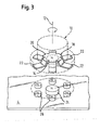
- FIG. 3 shows a schematic exploded view of the lifted off the surface of the glass ceramic plate 4 control knob 10.
- the grouping of the permanent magnets below the glass ceramic plate 4 and the arrangement of the magnetic elements of the control knob 10 are clearly visible.
- six each uniformly at the same distance around the central magnet 24 grouped ring magnets 26 are provided, the north pole N points upward in the direction of the control knob 10 and the south pole S in the opposite direction.
- the central magnet 24 has the same polarity with the north pole N upwards.
- the south pole S of the holding magnet 14 of the control knob 10 faces the knob base 16 and is therefore attracted by the central magnet 24.
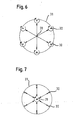
- FIGS. 4 and 5 illustrate in schematic representations, the arrangement of the pole spider 18 relative to the magnets 24, 26 of the control surface.
- the pole spider 4 is in this case with its central region 20, under which the holding magnets 14 is arranged, in each case above the uppermost of six ring magnets 26.
- FIG. 4 For example, the situation of a repulsive magnetic force is shown between the two adjacent uppermost crown magnets 26 and the arms 22 of the pole spider 18.
- FIG. 5 illustrates a rest position of the control knob, in which the arms 22 of the pole spider 18 are each located in spaces between adjacent ring magnets 26 of the control surface.
- a typical Auslenkweg can be between 3 and 20 mm.
- an activation area In the FIG. 5 is shown with dashed lines an activation area. Within the activation range, the six ring magnets 26 are arranged. An inner first boundary of the annular activation region extends concentrically around the central magnet 24 at a distance of 5 mm. To select one of the selection positions 30 assigned to the ring magnets 26, the control knob 10 must be pushed into the activation region. The distance is dimensioned such that eccentric rotational movements of the control knob in its initial position do not result in unintentional deflection of the control knob 10 to the rim magnet 26. An outer second boundary of the activation area extends in accordance with FIG. 5 concentric about the inner boundary and is spaced over a distance of 15 mm in the radial direction from the outer periphery of the central magnet 24. The control knob 10 is located between the first and second limits of the activation range, the magnetic restoring forces of the central magnet 24 are still large enough to support a provision of the control knob 10 in its initial position 28.
- the entire selection process of the control knob does not last longer than 2 seconds.
- the selection of the operating function for example the selection of one of the hotplates 8, is not detected.
- an annular luminous segment 31 is preferably used as the optical stop at the defined deflection width and deflection direction. The lighting segment preferably illuminates at the moment when the edge of the control knob has just reached the predetermined deflection range. The light mark under the glass ceramic cover is just reached from the edge of the control knob, without covering it. Supporting a short beep can be used at this moment.
- both types of acknowledgment can also be used in mixed form, for example to distinguish main deflection directions from subordinate deflection directions.
- the light mark is used to select hotplates and lights until a different hotplate is selected. Subsequently, by turning the control knob in the middle position, the cooking level of the selected and displayed cooking position can be set and changed at any time without prior deflection.
- the rotary knob for example, according FIG. 6 are pushed in a view from above from the central starting position 28 in six different selection positions 30. In these selection positions 30, the control knob can then be rotated in each case. To reduce the heating level of a cooking area 8, the control knob can thus be pushed into the appropriate selection position 30 and rotated by turning counterclockwise. Due to the sufficient distance between the central magnet and the ring magnet, the control knob remains in the selected selection position 30 and can be rotated there.
- the operation of the control knob can alternatively be done as follows.
- an operating function ie the desired hotplate 8
- the control knob is pushed by the operator from the middle starting position 28 into the corresponding selection position 30.
- the operator moves the control knob back to the central starting position 28 back.
- the setting of the operating parameter ie the heating level of the selected cooking point 8 then takes place by turning the control knob in the central starting position 28.
- a stepwise increase or decrease of the heating level of a selected cooking point 8 by repeated sliding of the control knob from the starting position 28 into the appropriate selection position 30 takes place.
- a connection of the functionality of the control knob according to the invention with additional touch sensors is possible to realize, for example, an independent main switch. Removing the control knob during operation could switch off all cooking zones after a warning phase and thus intervene in the main switch on one side. This warning can be acoustic and / or optical. Other functions can be occupied in both variants by repeatedly deflecting in the same direction in a so-called toggle mode, such as a zoning circuit.
- a significant advantage of the arrangement of the control unit according to the invention is that the central control knob is easy to clean and remove and in this way also allows the cleaning of the completely planar glass ceramic plate, which also has no breakthroughs or heels.
- the entire operating area with its printing and the luminous markings grouped in its vicinity can be very small and therefore space-saving. It is as easy to clean as a cooktop with touch control, without causing their disadvantages are connected, such as the inevitable fingerprints and the effects of heat when touching a possibly hot glass ceramic surface.
Landscapes
- Engineering & Computer Science (AREA)
- Physics & Mathematics (AREA)
- Automation & Control Theory (AREA)
- General Physics & Mathematics (AREA)
- Chemical & Material Sciences (AREA)
- Mechanical Engineering (AREA)
- General Engineering & Computer Science (AREA)
- Combustion & Propulsion (AREA)
- Ceramic Engineering (AREA)
- Switches With Compound Operations (AREA)
- Mechanical Control Devices (AREA)
- Brushes (AREA)
- Food-Manufacturing Devices (AREA)
- Control Of Electric Motors In General (AREA)
- Electric Stoves And Ranges (AREA)
Abstract
Description
Die vorliegende Erfindung betrifft eine Bedieneinheit für ein elektrisches Haushaltsgerät zum Einstellen von Betriebsfunktionen und -parametern mit einem an einer Bedienfläche gehalterten Bedienknebel, der zum Auswählen einer Betriebsfunktion, wie der Auswahl einer Kochstelle, aus einer Ausgangsstellung in eine Auswahlstellung verschiebbar ist und der zum Einstellen des Betriebsparameters, wie einer Heizstufe, um eine Knebelachse drehbar ist.The present invention relates to an operating unit for a household electrical appliance for setting operating functions and parameters with a content Erten on a control surface control knob, which is displaceable for selecting an operating function, such as the selection of a hotplate, from a starting position to a selection position and for setting the Operating parameters, such as a heating stage, is rotatable about a toggle axis.
Eine gattungsgemäße Bedieneinheit für ein elektrisches Haushaltsgerät ist in der
Aus der
Die Aufgabe der vorliegenden Erfindung besteht darin, eine Bedieneinheit nach dem Oberbegriff des Patentanspruchs 1 so zu verbessern, dass sich eine leichte Bedienbarkeit sowie eine einfach aufgebaute und in der Funktion verbesserte Koppelung mit dem Haushaltsgerät ergibt.The object of the present invention is to improve a control unit according to the preamble of claim 1 so that there is an easy operability and a simple design and improved in function coupling with the household appliance.
Erfindungsgemäß wird diese Aufgabe bei einer Bedieneinheit nach dem Oberbegriff des Anspruchs 1 dadurch gelöst, dass zur magnetischen Halterung des Bedienknebels im Bereich der Platte eine Magnetanordnung mit mehreren ortsfest angeordneten Magneten vorgesehen ist, welche einen Zentralmagneten und eine Anzahl von, insbesondere wenigstens drei, jeweils um diesen verteilte Kranzmagneten aufweist, und welche auf wenigstens einen Permanentmagneten und/oder ein ferromagnetisches Element des Bedienknebels eine magnetische Anziehungskraft ausübt und Dreh- und Verschiebebewegungen des Bedienknebels ermöglicht, dass entlang der Platte beabstandet vom Umfang des Zentralmagneten ein Aktivierungsbereich zur Aktivierung der ausgewählten Bedienfunktion vorgesehen ist, wobei zum Auswählen einer der den Kranzmagneten zugeordneten Auswahlstellungen der Bedienknebel in den Aktivierungsbereich geschoben wird, dass der Aktivierungsbereich durch eine zum Zentralmagneten benachbarte erste Begrenzung und durch eine zum Zentralmagneten weiter beabstandete zweite Begrenzung begrenzt ist, und dass die erste Begrenzung des Aktivierungsbereiches über einen Abstand von wenigstens 5 mm vom Umfang des Zentralmagneten entfernt ist.According to the invention this object is achieved in an operating unit according to the preamble of claim 1, characterized in that for magnetic support of the control knob in the region of the plate, a magnet arrangement is provided with a plurality of stationary magnets, which a central magnet and a number of, in particular at least three, each having this distributed ring magnet, and which exerts on at least one permanent magnet and / or a ferromagnetic element of the control knob a magnetic attraction and rotation and displacement movements of the control knob allows along the plate spaced from the circumference of the central magnet an activation area for activating the selected operating function is provided , Wherein, for selecting one of the wreath magnets associated selection positions of the control knob is pushed into the activation area, that the activation area by a central magnet adjacent to the first boundary u nd is limited by a second boundary further spaced from the central magnet, and that the first boundary of the activation region is at a distance of at least 5 mm from the circumference of the central magnet.
Im Bereich der Platte sind vorzugsweise ein Zentralmagnet und mehrere in einem vorgegebenen Abstand jeweils gleichmäßig ringförmig um diesen gruppierte Kranzmagneten vorgesehen. Jeder der Kranzmagneten definiert eine der möglichen Auswahlstellungen, in die der Bedienknebel geschoben werden kann. Bei vier vorhandenen Betriebsfunktionen, beispielsweise vier Kochstellen eines elektrischen Herdes, sind wenigstens vier verschiedene Auswahlstellungen notwendig. In einer vorteilhaften Weiterbildung der Erfindung können jedoch zusätzliche Auswahlstellungen vorgesehen sein, die mit Zusatzfunktionen belegt sind. So können beispielsweise bei einem elektrischen Herd sechs Auswahlstellungen zur Auswahl von vier Kochstellen sowie zur Steuerung von Zusatzfunktionen vorgesehen sein. Solche Zusatzfunktionen können beispielsweise eine Timersteuerung, eine zentrale Zonenzuschaltung oder dergleichen sein. Sind sechs solcher Auswahlstellungen vorgesehen, sind entsprechend sechs um den Zentralmagneten gruppierte Kranzmagneten notwendig.In the area of the plate, a central magnet and a plurality of ring magnets, which are each uniformly annularly arranged around this grouped ring magnet, are preferably provided. Each of the ring magnets defines one of the possible selection positions into which the control knob can be pushed. With four existing operating functions, for example four cooking zones of an electrical cooker, at least four different selection positions are necessary. In an advantageous development of the invention, however, additional selection positions can be provided which are assigned additional functions. Thus, for example, in an electric range, six selection positions can be provided for selecting four cooking positions and for controlling additional functions. Such additional functions may be, for example, a timer control, a central zone connection or the like. If six such selection positions are provided, correspondingly six ring magnets grouped around the central magnet are necessary.
In einem Abstand vom Außenumfang des Zentralmagneten ist ein Aktivierungsbereich vorgesehen, in den der Bedienknebel zum Auswählen der Bedienfunktion geschoben werden muss. Der Abstand zum Aktivierungsbereich verhindert, dass der Bedienknebel bei einer Drehbewegung in seiner Ausgangsstellung unbeabsichtigt in die Auswahlstellung verschoben wird. Daher ist eine gewisse exzentrische Drehbewegung des Bedienknebels in seiner Ausgangsstellung ermöglicht, ohne unbeabsichtigt eine Auswahlstellung auszuwählen. Als besonders vorteilhaft hat sich ein Abstand zwischen dem Aktivierungsbereich und dem Zentralmagneten von zumindest 5 mm erwiesen.At a distance from the outer circumference of the central magnet an activation area is provided, in which the control knob must be pushed to select the operating function. The distance to the activation area prevents the control knob is moved unintentionally in the selection position during a rotary motion in its initial position. Therefore, a certain eccentric rotational movement of the control knob is possible in its initial position without unintentionally selecting a selection position. A distance between the activation region and the central magnet of at least 5 mm has proven to be particularly advantageous.
Mit einer solchen erfindungsgemäßen Bedieneinheit ist eine einfache und übersichtliche Bedienung des elektrischen Haushaltsgeräts ermöglicht. So kann durch Verschieben des Bedienknebels aus einer Ausgangsstellung in eine Auswahlstellung eine Betriebsfunktion ausgewählt werden, die beispielsweise in der Auswahl einer bestimmten Kochstelle eines elektrischen Herdes besteht. Durch Drehen des Bedienknebels in herkömmlicher Art und Weise kann ein Betriebsparameter der zuvor ausgewählten Betriebsfunktion beeinflusst werden. Durch Drehen des Bedienknebels um seine Knebelachse kann beispielsweise eine Heizstufe der zuvor ausgewählten Kochstelle beeinflusst werden. Der Bedienknebel kann vom ersten Bedienschritt, der Auswahl der Betriebsfunktion bis zum zweiten Bedienschritt, dem Einstellen des Betriebsparameters der ausgewählten Betriebsfunktion, unverändert in der Hand einer Bedienperson verbleiben. Ein Griffwechsel oder die Betätigung eines Zusatzelementes der Bedieneinheit ist nicht erforderlich. Zudem ist jedem Bedienschritt eine eigene, charakteristische Bewegungsart des Bedienknebels zugeordnet. Durch die zusammenwirkenden Permanentmagneten der Bedienfläche und des Bedienknebels kann dieser von der Platte abgezogen werden und nahezu beliebig auf der Platte verschoben und/oder verdreht werden. Die Platte kann völlig plan ausgestaltet sein und kann auf diese Weise optimal von anhaftendem Schmutz gereinigt werden. Alle möglichen Verschiebe- und Drehbewegungen des Bedienknebels werden ausschließlich durch die Gestaltung der zusammenwirkenden magnetischen Elemente definiert.With such an operating unit according to the invention a simple and clear operation of the electrical household appliance is possible. Thus, by moving the control knob from a starting position into a selection position, an operating function can be selected which, for example, consists in the selection of a specific hotplate of an electric cooker. By turning the control knob in a conventional manner, an operating parameter of the previously selected operating function can be influenced. By turning the control knob about its toggle axis, for example, a heating level of the previously selected cooking position can be influenced. The control knob can remain unchanged from the first operating step, the selection of the operating function to the second operating step, the setting of the operating parameter of the selected operating function, in the hands of an operator. A handle change or the operation of an additional element of the control unit is not required. In addition, each operating step is assigned its own, characteristic movement type of the control knob. Through the cooperating permanent magnets of the control surface and the control knob, this can be subtracted from the plate and moved almost anywhere on the plate and / or rotated. The plate can be designed completely flat and can be optimally cleaned in this way of adhering dirt. All possible sliding and rotating movements of the control knob are defined solely by the design of the cooperating magnetic elements.
Eine Anschlagsstellung in jeweils einer der Auswahlstellungen kann gemäß einer Ausgestaltung der Erfindung durch ein optisches und/oder akustische Signal angezeigt werden. Auf diese Weise wird der Bedienperson angezeigt, dass sich der Bedienknebel in der Auswahlstellung befindet und nicht weiter über diese hinausgeschoben werden sollte. Eine Sicherheitsfunktion kann beispielsweise darin bestehen, dass die zuvor angewählte Betriebsfunktion bei Abnehmen des Bedienknebels oder bei zu weitem Schieben über seine Anschlagstellung hinaus abgeschaltet wird.An abutment position in each case one of the selection positions can be displayed according to an embodiment of the invention by an optical and / or acoustic signal. In this way, the operator is shown that the control knob is in the selection position and should not be postponed beyond this. A safety function may be, for example, that the previously selected operating function is switched off on its removal position when removing the control knob or pushing too far.
Die Abtastung und Erfassung der Verschiebe- und Drehbewegungen des Bedienknebels kann in an sich bekannter Weise auf induktivem, auf optischem oder auf magnetischem Wege erfolgen. Die erwähnten Abtastverfahren können ggf. auch miteinander kombiniert werden.The scanning and detection of the displacement and rotational movements of the control knob can be done in a conventional manner on inductive, optical or magnetic way. If necessary, the mentioned sampling methods can also be combined with each other.
Eine erste Ausgestaltung der Erfindung sieht vor, dass der Bedienknebel aus jeder der Auswahlstelllungen selbsttätig in die Ausgangsstellung zurückgleitet. Eine alternative Ausgestaltung kann darin bestehen, dass der Bedienknebel in jeder oder nur in einigen der Auswahlstellungen verbleibt und aus diesen durch Zurückschieben in die Ausgangsstellung gebracht werden muss. Diese alternativen Konfigurationen können jeweils durch geeignete Gestaltungen und Anordnungen der miteinander kommunizierenden magnetischen Elemente realisiert werden.A first embodiment of the invention provides that the control knob from each of the selector positions automatically slides back into the starting position. An alternative embodiment may consist in that the control knob remains in each or only in some of the selection positions and must be brought out of these by pushing back into the starting position. These alternative configurations can each be realized by suitable designs and arrangements of the magnetic elements communicating with each other.
Eine Ausgestaltung der Erfindung sieht an einer Unterseite des Bedienknebels einen Haltemagneten sowie eine ferromagnetische Scheibe mit wenigstens drei Armen vor. Vorzugsweise weist die ferromagnetische Scheibe, die beispielsweise als Polspinne aus Weicheisen ausgebildet sein kann, ebenso viele Arme auf, wie Kranzmagneten in bzw. an der Bedienfläche vorhanden sind. Die Polspinne aus Weicheisen bewirkt eine Magnetisierung der Arme in einer zur Unterseite des Haltemagneten entgegengesetzten Polung. Auf diese Weise können die Positionierungen der Arme auf den entsprechenden Kranzmagneten eine Abstoßung oder Anziehung bewirken, je nachdem wie die Kranzmagneten orientiert sind. Vorzugsweise sind die Kranzmagneten in gleicher Polung angeordnet wie der Zentralmagnet der Bedienfläche. Auf diese Weise kann der Bedienknebel mit seinen Haltemagneten auf einen der Kranzmagneten geschoben werden und unterliegt dabei einer magnetischen Anziehung. Da die Polspinne aus Weicheisen vorzugsweise die entgegengesetzte Polung wie die Unterseite des Bedienknebels aufweist, wird beim Drehen des Bedienknebels eine Rastung bewirkt, die durch die abstoßenden Kräfte beim Überstreichen der Arme der Polspinne über die Kranzmagneten bzw. den Zentralmagneten bewirkt wird.An embodiment of the invention provides a holding magnet and a ferromagnetic disk with at least three arms on an underside of the control knob. Preferably, the ferromagnetic disc, which may be formed, for example, as a pole spider made of soft iron, as many arms, as wreath magnets are present in or on the control surface. The pole spider made of soft iron causes a magnetization of the arms in a polarity opposite to the underside of the holding magnet. In this way, the positioning of the arms on the corresponding rim magnets can cause repulsion or attraction, depending on how the ring magnets are oriented. Preferably, the ring magnets are arranged in the same polarity as the central magnet of the control surface. In this way, the control knob can be pushed with its holding magnets on one of the ring magnets and is subject to a magnetic attraction. Since the pole spider of soft iron preferably has the opposite polarity as the underside of the control knob, a detent is caused when turning the control knob, which is caused by the repulsive forces when sweeping the arms of the pole spider on the ring magnets or the central magnet.
Zur Steuerung von zwei oder drei Betriebsfunktionen kann wahlweise jeweils ein Bedienknebel vorgesehen sein, der dem entsprechend zwei oder drei Auswahlstellungen aufweist. Ebenso kann ein Bedienknebel mehrere Auswahlstellungen, beispielsweise sechs oder acht, aufweisen, so dass zur umfassenden Steuerung eines elektrischen Geräts ein Bedienknebel ausreichen kann.For controlling two or three operating functions, one control knob can optionally be provided, which has two or three selection positions correspondingly. Likewise, a control knob several selection positions, for example six or eight, so that for comprehensive control of an electrical device, a control knob may be sufficient.
Ferner ist es von Vorteil, wenn eine äußere Begrenzung des Aktivierungsbereiches etwa bis zu 15 mm von dem Umfang des Zentralmagneten beabstandet ist. Dadurch sind noch ausreichend große magnetische Rückstellkräfte des Zentralmagneten gewährleistet, um ein Zurückstellen des Bedienknebels vom Aktivierungsbereich in die Ausgangsstellung zu unterstützen. Außerdem ergibt sich daraus für die Bedienperson eine kurze und daher komfortable Auslenkweglänge des Bedienknebels. Zugleich ist der Platzbedarf der gesamten Bedieneinheit in dem Haushaltsgerät hinreichend reduziert. Die flächige Ausbildung des Aktivierungsbereiches gewährleistet zudem ein zuverlässiges Erfassen einer Verschiebebewegung des Bedienknebels. Dies ist insbesondere bei einer nur in Zeitintervallen erfolgenden induktiven und/oder optischen Abtastung des Bedienknebels von Bedeutung.Furthermore, it is advantageous if an outer boundary of the activation region is spaced approximately 15 mm from the circumference of the central magnet. As a result, sufficiently large magnetic restoring forces of the central magnet are ensured in order to support a reset of the control knob from the activation area to the starting position. In addition, this results in a short and therefore comfortable Auslenkweglänge the control knob for the operator. At the same time, the space requirement of the entire operating unit in the household appliance is sufficiently reduced. The planar design of the activation area also ensures reliable detection of a sliding movement of the control knob. This is particularly important in an inductive and / or optical scanning of the control knob, which takes place only in time intervals.
Sicherheitstechnisch vorteilhaft kann die mit dem Bedienknebel vorgenommene Auswahl einer Betriebsfunktion nur dann erfasst werden, wenn der Bedienknebel nach Ablauf eines vorgegebenen Zeitintervalles wieder in seine Ausgangsstellung zurückgestellt wird. Ist dies nicht der Fall, kann von einer Störung des Auswahlvorgangs ausgegangen werden. Das Zeitintervall liegt bevorzugt zwischen zwei bis fünf Sekunden.In terms of safety, the selection of an operating function made with the control knob can only be detected if the control knob is returned to its initial position after a predetermined time interval has expired. If this is not the case, it can be assumed that the selection process has been disrupted. The time interval is preferably between two to five seconds.
Die Erfindung wird nachfolgend anhand von Ausführungsbeispielen der erfindungsgemäßen Bedieneinheit am Beispiel eines Kochfeldes beschrieben. Es zeigen:
- Figur 1
- eine perspektivische Ansicht eines Kochfeldes mit einer Bedieneinheit,
- Figur 2
- eine schematische Schnittansicht eines Bedienknebels der Bedieneinheit,
- Figur 3
- eine Explosionsdarstellung der erfindungsgemäßen Bedieneinheit zur Verdeutlichung der zusammen wirkenden magnetischen Elemente der Bedienfläche und des Bedienknebels,
Figuren 4 und 5- schematische Darstellungen der zusammen wirkenden magnetischen Elemente der Bedienfläche und des Bedienknebels und
Figuren 6 und 7- Prinzipdarstellungen verschiedener Betätigungsvarianten der Bedieneinheit.
- FIG. 1
- a perspective view of a hob with a control unit,
- FIG. 2
- a schematic sectional view of a control knob of the control unit,
- FIG. 3
- an exploded view of the control unit according to the invention to illustrate the cooperating magnetic elements of the control surface and the control knob,
- FIGS. 4 and 5
- schematic representations of the cooperating magnetic elements of the control surface and the control knob and
- FIGS. 6 and 7
- Schematic representations of various operating variants of the operating unit.
Die Erfassung der Verschiebebewegungen des Bedienknebels 10 zur Auswahl der zur Verfügung stehenden Betriebsfunktionen sowie der Drehbewegungen zur Auswahl der zur Verfügung stehenden Betriebsparameter des elektrischen Haushaltsgeräts kann in bekannter Weise, bspw. mittels induktiver und/oder optischer Abtastung erfolgen. Diese Abtastverfahren ermöglichen jeweils eine präzise berührungsfreie Signalübertragung und damit eine zuverlässige Bedienung des elektrischen Haushaltsgeräts.The detection of the displacement movements of the
Die
In der
Aus sicherheitstechnischen Gründen darf gemäß dem Ausführungsbeispiel der
Bei einem Überschreiten des Zeitintervalls wird die Auswahl der Betriebsfunktion, etwa die Auswahl einer der Kochstellen 8, nicht erfasst.If the time interval is exceeded, the selection of the operating function, for example the selection of one of the
Während des Auslenkvorgangs ist eine optische und/oder akustische Quittierung mittels einer Signaleinrichtung 31, wie in
Zum Bedienen der Bedieneinheit kann der Drehknebel beispielsweise gemäß
Gemäß
In beiden gezeigten Varianten ist eine Verbindung der erfindungsgemäßen Funktionalität des Bedienknebels mit zusätzlichen Berührungssensoren möglich, um beispielsweise einen unabhängigen Hauptschalter zu realisieren. Das Abnehmen des Bedienknebels während des Betriebs könnte nach einer Warnphase alle Kochstellen abschalten und damit in den Hauptschalter einseitig eingreifen. Diese Warnung kann akustisch und/oder optisch erfolgen. Weitere Funktionen können in beiden Varianten durch mehrmaliges Auslenken in dieselbe Richtung auch in einem sogenannten Toggle-Modus belegt werden, wie beispielsweise eine Zonenzuschaltung.In both variants shown, a connection of the functionality of the control knob according to the invention with additional touch sensors is possible to realize, for example, an independent main switch. Removing the control knob during operation could switch off all cooking zones after a warning phase and thus intervene in the main switch on one side. This warning can be acoustic and / or optical. Other functions can be occupied in both variants by repeatedly deflecting in the same direction in a so-called toggle mode, such as a zoning circuit.
Ein bedeutender Vorteil der erfindungsgemäßen Anordnung der Bedieneinheit liegt darin, dass der zentrale Bedienknebel leicht reinigbar und abnehmbar ist und auf diese Weise auch die Reinigung der völlig planen Glaskeramikplatte ermöglicht, die zudem keinerlei Durchbrüche oder Absätze aufweist. Der gesamte Bedienbereich mit seiner Bedruckung und den in seiner Nähe gruppierten Leuchtmarkierungen kann sehr klein und damit platzsparend ausgeführt sein. Er ist ebenso leicht zu reinigen wie eine Kochmulde mit Berührsteuerung, ohne dass damit deren Nachteile verbunden sind, wie beispielsweise den unvermeidlichen Fingerabdrücken sowie den Wärmeeinflüssen bei der Berührung einer eventuell heißen Glaskeramikoberfläche.A significant advantage of the arrangement of the control unit according to the invention is that the central control knob is easy to clean and remove and in this way also allows the cleaning of the completely planar glass ceramic plate, which also has no breakthroughs or heels. The entire operating area with its printing and the luminous markings grouped in its vicinity can be very small and therefore space-saving. It is as easy to clean as a cooktop with touch control, without causing their disadvantages are connected, such as the inevitable fingerprints and the effects of heat when touching a possibly hot glass ceramic surface.
- 22
- Kochfeldhob
- 44
- GlaskeramikplatteGlass ceramic plate
- 66
- PlattenfacettePlattenfacette
- 88th
- Kochstellecooking
- 1010
- Bedienknebelcontrol knobs
- 1212
- KnebelachseKnebel axis
- 1414
- Haltemagnetholding magnet
- 1616
- KnebelunterseiteKnebel bottom
- 1818
- Polspinnepole spider
- 2020
- ZentralbereichCentral area
- 2222
- Armpoor
- 2424
- ZentralmagnetCentral magnet
- 2626
- Kranzmagnetwreath magnet
- 2828
- Ausgangsstellungstarting position
- 3030
- Auswahlstellungselection position
- 3131
- Signaleinrichtungsignaling device
- 3232
- Aktivierungsbereichactivation area
- 3333
- Erste BegrenzungFirst limit
- 3434
- Zweite BegrenzungSecond limit
- NN
- Nordpol (Magnet)North Pole (magnet)
- SS
- Südpol (Magnet)South Pole (magnet)
Claims (14)
- Control unit for an electrical domestic appliance for setting operating functions and operating parameters, with at least one control knob (10) which is magnetically mounted on a plate (4) and which for selection of an operating function, such as the selection of a cooking position (8), can be pushed from a starting setting (28) into a selection setting (30), and which for setting the operating parameter, such as a heating step, is rotatable about a knob axis (12), characterised in that provided for magnetic mounting of the control knob (10) in the region of the plate (4) is a magnet arrangement with several magnets (24, 26), which are arranged to be stationary and comprise a central magnet (24) and a number of, in particular at least three, circle magnets (26) distributed around the central magnet and which exert a magnetic attraction force on at least one permanent magnet (14) and/or ferromagnetic element (18) of the control knob (10) and enable rotational and sliding movements of the control knob (10), that an activation region for activation of the selected control function (8) is provided along the plate (4) at a spacing from the circumference of the central magnet (24), wherein for selection of one of the selection settings associated with the circle magnets (26) the control knob (10) is pushed into the activation region, that the activation region is bounded by a first boundary adjacent to the central magnet (24) and by a second boundary spaced further from the central magnet (24) and that the first boundary of the activation region is spaced from the circumference of the central magnet (24) over a distance of at least 5 millimetres.
- Control unit according to claim 1, characterised in that an optical and/or acoustic signal device (31) indicates the selection setting (30) of the control knob (10).
- Control unit according to claim 1 or 2, characterised in that the control knob (10) is designed in order to automatically slide back from the selection setting (30) into the starting setting (28).
- Control unit according to claim 1 or 2, characterised in that the control knob (10) is designed to be brought from the selection setting (30) into the starting setting (28) by pushing back.
- Control unit according to any one of the preceding claims, characterised in that the control knob (10) comprises a mounting magnet (14) as well as a ferromagnetic disc (18) with at least three arms (22) at an underside (16) of the control knob (10).
- Control unit according to claim 5, characterised in that the ferromagnetic disc is formed as a pole spider (18) of soft iron.
- Control unit according to claim 6, characterised in that the number and arrangement of arms (22) of the pole spider (18) correspond with the number of circle magnets (26).
- Control unit according to any one of claims 5 to 7, characterised in that for exertion of the magnetic attraction force the central magnet (24) or the circle magnets (26) is or are disposed with opposite poling opposite the mounting magnet (14) of the control knob (10).
- Control unit according to any one of claims 5 to 8, characterised in that for producing repulsively acting magnetic forces the arms (22) of the ferromagnetic pole spider or disc (18) are disposed with the same poling opposite the circle magnets (26) or the central magnet (24).
- Control unit according to any one of the preceding claims, characterised in that the control knob (10) is designed for setting at least two operating functions.
- Control unit according to any one of the preceding claims, characterised in that the second boundary of the activation region is spaced from the circumference of the central magnet (24) over a distance of up to 15 millimetres.
- Control unit according to any one of the preceding claims, characterised in that the selection of the operating function (8) by the control knob (10) is detected only when the control knob (10) is restored again to the starting setting (28) after a predetermined time interval.
- Control unit according to claim 12, characterised in that the predetermined time interval is between two and five seconds.
- Control unit according to any one of the preceding claims, characterised in that the circle magnets (26) are uniformly distributed around the circumference of the central magnet (24).
Priority Applications (2)
| Application Number | Priority Date | Filing Date | Title |
|---|---|---|---|
| EP07118614A EP1873609B1 (en) | 2002-08-14 | 2003-07-21 | Control unit for electric household appliance |
| EP07118708A EP1873610B1 (en) | 2002-08-14 | 2003-07-21 | Control unit for electric household appliance |
Applications Claiming Priority (5)
| Application Number | Priority Date | Filing Date | Title |
|---|---|---|---|
| DE10237289 | 2002-08-14 | ||
| DE10237289 | 2002-08-14 | ||
| DE10244917 | 2002-09-25 | ||
| DE10244917 | 2002-09-25 | ||
| PCT/EP2003/007951 WO2004019150A1 (en) | 2002-08-14 | 2003-07-21 | Control unit for electric household appliance |
Related Child Applications (4)
| Application Number | Title | Priority Date | Filing Date |
|---|---|---|---|
| EP07118708A Division EP1873610B1 (en) | 2002-08-14 | 2003-07-21 | Control unit for electric household appliance |
| EP07118614A Division EP1873609B1 (en) | 2002-08-14 | 2003-07-21 | Control unit for electric household appliance |
| EP07118614.2 Division-Into | 2007-10-16 | ||
| EP07118708.2 Division-Into | 2007-10-17 |
Publications (2)
| Publication Number | Publication Date |
|---|---|
| EP1530749A1 EP1530749A1 (en) | 2005-05-18 |
| EP1530749B1 true EP1530749B1 (en) | 2010-02-24 |
Family
ID=31947606
Family Applications (3)
| Application Number | Title | Priority Date | Filing Date |
|---|---|---|---|
| EP07118614A Expired - Lifetime EP1873609B1 (en) | 2002-08-14 | 2003-07-21 | Control unit for electric household appliance |
| EP03792219A Expired - Lifetime EP1530749B1 (en) | 2002-08-14 | 2003-07-21 | Control unit for electric household appliance |
| EP07118708A Expired - Lifetime EP1873610B1 (en) | 2002-08-14 | 2003-07-21 | Control unit for electric household appliance |
Family Applications Before (1)
| Application Number | Title | Priority Date | Filing Date |
|---|---|---|---|
| EP07118614A Expired - Lifetime EP1873609B1 (en) | 2002-08-14 | 2003-07-21 | Control unit for electric household appliance |
Family Applications After (1)
| Application Number | Title | Priority Date | Filing Date |
|---|---|---|---|
| EP07118708A Expired - Lifetime EP1873610B1 (en) | 2002-08-14 | 2003-07-21 | Control unit for electric household appliance |
Country Status (11)
| Country | Link |
|---|---|
| US (1) | US8440945B2 (en) |
| EP (3) | EP1873609B1 (en) |
| JP (1) | JP4050276B2 (en) |
| KR (1) | KR20050050078A (en) |
| CN (1) | CN100533329C (en) |
| AT (1) | ATE459032T1 (en) |
| AU (1) | AU2003246724A1 (en) |
| DE (1) | DE50312450D1 (en) |
| ES (1) | ES2340030T3 (en) |
| TW (1) | TW200404145A (en) |
| WO (1) | WO2004019150A1 (en) |
Families Citing this family (60)
| Publication number | Priority date | Publication date | Assignee | Title |
|---|---|---|---|---|
| US7906875B2 (en) | 1999-01-19 | 2011-03-15 | Touchsensor Technologies, Llc | Touch switches and practical applications therefor |
| FR2872957B1 (en) * | 2004-07-08 | 2006-09-22 | Sc2N Sa | MAGNETIC INDEX CONTROL DEVICE |
| DE102007002189B4 (en) * | 2006-10-31 | 2010-04-01 | Preh Gmbh | Turntable with magnetically generated feel |
| DE102007016466B3 (en) * | 2007-03-16 | 2008-08-21 | E.G.O. Elektro-Gerätebau GmbH | Operating device for use in hob, has sensor unit e.g. hall-sensor and optical distance sensor, laterally arranged in movement section of signal unit, where operating device is formed without internal energy supply |
| DE102008013003A1 (en) * | 2008-03-07 | 2009-09-10 | BSH Bosch und Siemens Hausgeräte GmbH | Operating device for a household appliance with an actuating knob and method for operating an operating device |
| DE102008017779A1 (en) * | 2008-04-08 | 2009-10-22 | BSH Bosch und Siemens Hausgeräte GmbH | Cooking hob comprises removable, slidable and movable control element, cover plate, and sensor arrangement arranged under cover plate for detecting position and rotation of control element |
| JP5143090B2 (en) * | 2008-06-10 | 2013-02-13 | 三菱電機株式会社 | Induction heating cooker |
| WO2010037567A1 (en) * | 2008-10-02 | 2010-04-08 | BSH Bosch und Siemens Hausgeräte GmbH | Domestic appliance device |
| DE102009000383A1 (en) * | 2009-01-23 | 2010-07-29 | BSH Bosch und Siemens Hausgeräte GmbH | Operating device of a household appliance |
| DE102009001979A1 (en) * | 2009-03-30 | 2010-10-14 | BSH Bosch und Siemens Hausgeräte GmbH | Operating device for a domestic appliance, domestic appliance with such an operating device and method for operating a domestic appliance with an operating device |
| US20100253653A1 (en) * | 2009-04-03 | 2010-10-07 | Touchsensor Technologies, Llc | Virtual knob interface and method |
| EP2256414A3 (en) * | 2009-05-27 | 2012-07-18 | BSH Bosch und Siemens Hausgeräte GmbH | Operating assembly for a gas cooker |
| WO2010143244A1 (en) * | 2009-06-09 | 2010-12-16 | 三菱電機株式会社 | Induction heating cooking appliance |
| DE102009048494A1 (en) * | 2009-09-25 | 2011-04-07 | E.G.O. Elektro-Gerätebau GmbH | Method and device for operating an electrical appliance |
| CN102195633A (en) * | 2010-03-17 | 2011-09-21 | 张景棠 | Magnetically controlled trigger mechanism and its control method |
| EP2619504B1 (en) * | 2010-09-20 | 2015-08-19 | BSH Hausgeräte GmbH | Structure of a gas-valve unit |
| DE102010044146A1 (en) * | 2010-11-19 | 2012-05-24 | BSH Bosch und Siemens Hausgeräte GmbH | Operating device for a domestic appliance with a trough-shaped receptacle and domestic appliance, in particular hob, with such an operating device |
| DE102010063188A1 (en) * | 2010-12-16 | 2012-06-21 | BSH Bosch und Siemens Hausgeräte GmbH | Operating device for a domestic appliance with an electronic display panel and household appliance with such an operating device |
| US9565970B2 (en) * | 2011-04-14 | 2017-02-14 | Electrodomesticos Taurus Sl | Cooking system including a cooking hob and a cooking vessel |
| KR101251036B1 (en) * | 2011-06-21 | 2013-04-04 | (주)뮤트로닉스 | Manually Operated Rotational Knob Apparatus for Airtight Structure Using Magnets |
| USD696894S1 (en) * | 2011-10-28 | 2014-01-07 | Electrolux Home Products Corporation N.V. | Induction cooker |
| USD694569S1 (en) * | 2011-12-30 | 2013-12-03 | Western Industries, Inc. | Cook top |
| CN102722214A (en) * | 2012-06-28 | 2012-10-10 | 惠州市德赛西威汽车电子有限公司 | Knob |
| DE102012217347A1 (en) | 2012-09-26 | 2014-03-27 | BSH Bosch und Siemens Hausgeräte GmbH | Input device for electrical appliance |
| JP6143438B2 (en) * | 2012-11-12 | 2017-06-07 | 大阪瓦斯株式会社 | Cooker |
| JP6073111B2 (en) * | 2012-11-12 | 2017-02-01 | 大阪瓦斯株式会社 | Cooker |
| CN102997292B (en) * | 2012-11-30 | 2015-11-18 | 九阳股份有限公司 | A kind of rotation controlled electromagnetic oven convenient for cleaning |
| DE102013217268A1 (en) * | 2013-08-29 | 2015-03-05 | BSH Bosch und Siemens Hausgeräte GmbH | Operating device for a household appliance with a protrusion standing down on a control element base, which is magnetically supported |
| JP2016001079A (en) * | 2014-06-12 | 2016-01-07 | 株式会社ハーマン | Gas stove |
| DE102014216389A1 (en) * | 2014-08-19 | 2016-02-25 | BSH Hausgeräte GmbH | Operating device for a household appliance with stably positioned annular control element front part and household appliance with such an operating device |
| JP6377999B2 (en) * | 2014-08-21 | 2018-08-22 | 株式会社ハーマン | Gas stove |
| KR102236587B1 (en) | 2014-09-04 | 2021-04-06 | 삼성전자주식회사 | Induction apparatus and method for controlling temperature |
| US20170019958A1 (en) * | 2015-07-15 | 2017-01-19 | General Electric Company | Method for illuminating knobs of a cooking appliance |
| CN105863006B (en) * | 2016-04-07 | 2018-11-27 | 浙江欧琳生活健康科技有限公司 | A kind of sink of mobile knob magnetic control |
| CN105863003B (en) * | 2016-04-07 | 2019-02-15 | 浙江欧琳生活健康科技有限公司 | A kind of sink of magnetic control heating surrounding edge |
| DE102016206477B4 (en) * | 2016-04-18 | 2017-11-09 | E.G.O. Elektro-Gerätebau GmbH | Operating device for an electrical appliance and electrical appliance |
| FR3050367B1 (en) * | 2016-04-25 | 2019-01-25 | Eurokera S.N.C. | VITROCERAMIC PLATE FOR PLAN WORK OR FURNITURE |
| CN106027022B (en) * | 2016-06-12 | 2018-11-09 | 广东美的厨房电器制造有限公司 | The knob assembly and household electrical appliance of household electrical appliance |
| CN105977067B (en) * | 2016-06-12 | 2018-03-30 | 广东美的厨房电器制造有限公司 | The control method of the knob assemblies of household electrical appliance, household electrical appliance and knob assembly |
| KR102509991B1 (en) * | 2016-06-13 | 2023-03-13 | 엘지전자 주식회사 | Cooking apparatus using induction heeating |
| KR102539016B1 (en) * | 2016-09-01 | 2023-06-02 | 삼성전자주식회사 | Cooking apparatus and controlling method thereof |
| JP6223525B2 (en) * | 2016-09-30 | 2017-11-01 | 大阪瓦斯株式会社 | Cooker |
| DE102016224302A1 (en) * | 2016-12-07 | 2018-06-07 | BSH Hausgeräte GmbH | Household appliance, control device for a household appliance and method for controlling a household appliance |
| CN107065649B (en) * | 2017-02-28 | 2023-08-25 | 珠海格力电器股份有限公司 | Knob wire controller and control method and system thereof |
| US10447262B2 (en) | 2017-04-14 | 2019-10-15 | Haier Us Appliance Solutions, Inc. | Cooking appliance and knob assembly removably mounted to a control panel of the cooking appliance |
| US10302306B2 (en) | 2017-04-14 | 2019-05-28 | Haier Us Appliance Solutions, Inc. | Cooking appliance and knob assembly |
| US10510501B2 (en) * | 2017-04-19 | 2019-12-17 | Danfoss Power Solutions Inc. | Rotary knob controller |
| DE102017128820A1 (en) * | 2017-12-05 | 2019-06-06 | Vorwerk & Co. Interholding Gmbh | Actuation device with magnets |
| CN107785205B (en) * | 2017-12-12 | 2019-04-02 | 浙江昌德成电器有限公司 | A kind of more open type on-off switches |
| DE102018200337A1 (en) * | 2018-01-11 | 2019-07-11 | BSH Hausgeräte GmbH | Operating device for a household appliance |
| HK1252075A2 (en) * | 2018-03-28 | 2019-05-10 | Defond Electech Co., Ltd | A control system and device for use in controlling operation of an electrical appliance |
| CN108594929A (en) * | 2018-08-01 | 2018-09-28 | 广州周立功单片机科技有限公司 | Magnetic suck knob structure |
| DE102018216481A1 (en) * | 2018-09-26 | 2020-03-26 | BSH Hausgeräte GmbH | Cooking device with a ring-shaped, touch-sensitive operating area and a touch-sensitive operating strip, and method for operating a cooking device |
| FR3096184B1 (en) * | 2019-05-15 | 2021-07-30 | Gulplug | Three-phase electrical connection system |
| CN111059577B (en) * | 2019-12-12 | 2022-05-20 | 华帝股份有限公司 | Gear judgment method for kitchen range adopting magnetic induction knob |
| CN111245414A (en) * | 2020-01-19 | 2020-06-05 | 深圳拓邦股份有限公司 | A kind of adjustment device, kitchen appliance and control method |
| KR102539745B1 (en) | 2020-10-06 | 2023-06-02 | 에스케이매직 주식회사 | Holeless type-operation device for electric range |
| KR102846686B1 (en) * | 2020-10-21 | 2025-08-18 | 현대자동차주식회사 | In-vehicle control apparatus using detachable knob and method for controlling the same |
| KR102846687B1 (en) * | 2020-11-05 | 2025-08-18 | 현대자동차주식회사 | In-vehicle control apparatus using detachable knob and method for controlling the same |
| DE102021120243A1 (en) | 2021-08-04 | 2023-02-09 | Miele & Cie. Kg | Household appliance system with a household appliance and with at least one detachable toggle |
Family Cites Families (12)
| Publication number | Priority date | Publication date | Assignee | Title |
|---|---|---|---|---|
| US3692239A (en) * | 1971-02-11 | 1972-09-19 | Robertshaw Controls Co | Control system for a double burner oven or the like and improved parts and method for the same or the like |
| EP0041830A1 (en) * | 1980-06-10 | 1981-12-16 | Kenwood Manufacturing Company Limited | Touch switch |
| GB8725737D0 (en) * | 1987-11-03 | 1987-12-09 | Electrolux Ab | Control apparatus |
| JPH0233843A (en) | 1988-07-25 | 1990-02-05 | Hitachi Ltd | Scanning electronic microscope |
| DE59711012D1 (en) * | 1996-03-20 | 2003-12-24 | Ego Elektro Geraetebau Gmbh | Arrangement for controlling electrical controllable devices |
| DE19825310A1 (en) | 1998-06-05 | 1999-12-09 | Bsh Bosch Siemens Hausgeraete | Control unit for an electrical household appliance |
| DE19859105A1 (en) * | 1998-12-21 | 2000-06-29 | Ego Elektro Geraetebau Gmbh | Arrangement for controlling electrically controllable devices, in particular electric cooking devices |
| CN1114793C (en) * | 1999-01-28 | 2003-07-16 | 陈玉山 | Computer gas stove |
| DE19906365B4 (en) * | 1999-02-16 | 2009-02-26 | BSH Bosch und Siemens Hausgeräte GmbH | Hob with control |
| DE10212929A1 (en) | 2002-03-19 | 2003-10-02 | Ego Elektro Geraetebau Gmbh | Control device for an electrical device |
| DE10212954A1 (en) * | 2002-03-19 | 2003-10-02 | Ego Elektro Geraetebau Gmbh | Control device for an electrical device |
| DE10255676B4 (en) * | 2002-11-28 | 2021-04-01 | BSH Hausgeräte GmbH | Control unit for an electrical device |
-
2003
- 2003-07-21 AU AU2003246724A patent/AU2003246724A1/en not_active Abandoned
- 2003-07-21 EP EP07118614A patent/EP1873609B1/en not_active Expired - Lifetime
- 2003-07-21 EP EP03792219A patent/EP1530749B1/en not_active Expired - Lifetime
- 2003-07-21 EP EP07118708A patent/EP1873610B1/en not_active Expired - Lifetime
- 2003-07-21 DE DE50312450T patent/DE50312450D1/en not_active Expired - Lifetime
- 2003-07-21 WO PCT/EP2003/007951 patent/WO2004019150A1/en not_active Ceased
- 2003-07-21 CN CNB038191792A patent/CN100533329C/en not_active Expired - Lifetime
- 2003-07-21 JP JP2004530045A patent/JP4050276B2/en not_active Expired - Fee Related
- 2003-07-21 KR KR1020057002400A patent/KR20050050078A/en not_active Ceased
- 2003-07-21 ES ES03792219T patent/ES2340030T3/en not_active Expired - Lifetime
- 2003-07-21 AT AT03792219T patent/ATE459032T1/en not_active IP Right Cessation
- 2003-07-31 TW TW092120957A patent/TW200404145A/en unknown
-
2005
- 2005-02-14 US US11/059,085 patent/US8440945B2/en not_active Expired - Fee Related
Also Published As
| Publication number | Publication date |
|---|---|
| EP1530749A1 (en) | 2005-05-18 |
| CN1685295A (en) | 2005-10-19 |
| WO2004019150A1 (en) | 2004-03-04 |
| JP4050276B2 (en) | 2008-02-20 |
| ATE459032T1 (en) | 2010-03-15 |
| EP1873609A1 (en) | 2008-01-02 |
| US20050189820A1 (en) | 2005-09-01 |
| DE50312450D1 (en) | 2010-04-08 |
| AU2003246724A1 (en) | 2004-03-11 |
| ES2340030T3 (en) | 2010-05-28 |
| JP2005535866A (en) | 2005-11-24 |
| TW200404145A (en) | 2004-03-16 |
| KR20050050078A (en) | 2005-05-27 |
| CN100533329C (en) | 2009-08-26 |
| EP1873610B1 (en) | 2012-06-13 |
| EP1873610A1 (en) | 2008-01-02 |
| EP1873609B1 (en) | 2012-04-18 |
| US8440945B2 (en) | 2013-05-14 |
Similar Documents
| Publication | Publication Date | Title |
|---|---|---|
| EP1530749B1 (en) | Control unit for electric household appliance | |
| EP0962707B1 (en) | Control unit for electric household appliance | |
| EP1869368B1 (en) | Operator control device for an electric appliance | |
| DE10255676B4 (en) | Control unit for an electrical device | |
| EP0797227B1 (en) | Device to control electrically controlled apparatus | |
| EP2687936B1 (en) | Rotating knob control device | |
| EP2669582B1 (en) | Domestic appliance with rotating knob and method of operating a domestic appliance | |
| EP1775650A2 (en) | Operating device for an electric appliance | |
| DE202004017133U1 (en) | Controlling glass ceramic cooking hob unit has function selector magnetically coupled through the plate to permanent magnets to select a function | |
| EP2652406A1 (en) | Operator control device for a domestic appliance, having an electronic display panel, and a domestic appliance having such an operator control device | |
| EP2079964A1 (en) | Domestic appliance with rotary toggle | |
| DE19906365A1 (en) | Control element, e.g. for electrical cooker hob, with spherical or point contact surface on contact plate held on control element perpendicularly with respect to contact surface by spring force | |
| EP2652403B1 (en) | Domestic appliance having an operator control apparatus | |
| EP3737890B1 (en) | Household appliance | |
| DE102004005111A1 (en) | Home appliance control device | |
| EP2455669B1 (en) | Operating device for a domestic appliance with a recessed holder and domestic appliance, in particular hob, with such an operating device | |
| DE102018209552A1 (en) | Portable control element with base unit, rotation detection part and tiltable control part arranged on the base unit as well as control device for a cooking appliance | |
| EP0936643B1 (en) | Rotary switch assembly for electrical domestic devices | |
| DE102009001979A1 (en) | Operating device for a domestic appliance, domestic appliance with such an operating device and method for operating a domestic appliance with an operating device | |
| WO2008067998A2 (en) | Operating device for an electric appliance comprising contact switches and method for switching on a supplementary heating device | |
| DE102009001740B4 (en) | Domestic appliance device | |
| EP0640796B1 (en) | Baking oven | |
| DE4331551B4 (en) | Main switch for a household electrical appliance | |
| EP2455670B1 (en) | Operating device for a domestic appliance with a trough-shaped holder and domestic appliance, in particular cooktop, with such an operating device | |
| DE102020120603A1 (en) | Operating device and method for operating a system |
Legal Events
| Date | Code | Title | Description |
|---|---|---|---|
| PUAI | Public reference made under article 153(3) epc to a published international application that has entered the european phase |
Free format text: ORIGINAL CODE: 0009012 |
|
| 17P | Request for examination filed |
Effective date: 20050314 |
|
| AK | Designated contracting states |
Kind code of ref document: A1 Designated state(s): AT BE BG CH CY CZ DE DK EE ES FI FR GB GR HU IE IT LI LU MC NL PT RO SE SI SK TR |
|
| AX | Request for extension of the european patent |
Extension state: AL LT LV MK |
|
| DAX | Request for extension of the european patent (deleted) | ||
| 17Q | First examination report despatched |
Effective date: 20070417 |
|
| GRAP | Despatch of communication of intention to grant a patent |
Free format text: ORIGINAL CODE: EPIDOSNIGR1 |
|
| GRAS | Grant fee paid |
Free format text: ORIGINAL CODE: EPIDOSNIGR3 |
|
| GRAA | (expected) grant |
Free format text: ORIGINAL CODE: 0009210 |
|
| AK | Designated contracting states |
Kind code of ref document: B1 Designated state(s): AT BE BG CH CY CZ DE DK EE ES FI FR GB GR HU IE IT LI LU MC NL PT RO SE SI SK TR |
|
| REG | Reference to a national code |
Ref country code: GB Ref legal event code: FG4D Free format text: NOT ENGLISH |
|
| REG | Reference to a national code |
Ref country code: CH Ref legal event code: EP |
|
| REG | Reference to a national code |
Ref country code: IE Ref legal event code: FG4D Free format text: LANGUAGE OF EP DOCUMENT: GERMAN |
|
| REF | Corresponds to: |
Ref document number: 50312450 Country of ref document: DE Date of ref document: 20100408 Kind code of ref document: P |
|
| REG | Reference to a national code |
Ref country code: ES Ref legal event code: FG2A Ref document number: 2340030 Country of ref document: ES Kind code of ref document: T3 |
|
| REG | Reference to a national code |
Ref country code: NL Ref legal event code: VDEP Effective date: 20100224 |
|
| PG25 | Lapsed in a contracting state [announced via postgrant information from national office to epo] |
Ref country code: PT Free format text: LAPSE BECAUSE OF FAILURE TO SUBMIT A TRANSLATION OF THE DESCRIPTION OR TO PAY THE FEE WITHIN THE PRESCRIBED TIME-LIMIT Effective date: 20100625 |
|
| PG25 | Lapsed in a contracting state [announced via postgrant information from national office to epo] |
Ref country code: SI Free format text: LAPSE BECAUSE OF FAILURE TO SUBMIT A TRANSLATION OF THE DESCRIPTION OR TO PAY THE FEE WITHIN THE PRESCRIBED TIME-LIMIT Effective date: 20100224 Ref country code: FI Free format text: LAPSE BECAUSE OF FAILURE TO SUBMIT A TRANSLATION OF THE DESCRIPTION OR TO PAY THE FEE WITHIN THE PRESCRIBED TIME-LIMIT Effective date: 20100224 |
|
| REG | Reference to a national code |
Ref country code: IE Ref legal event code: FD4D |
|
| PG25 | Lapsed in a contracting state [announced via postgrant information from national office to epo] |
Ref country code: CY Free format text: LAPSE BECAUSE OF FAILURE TO SUBMIT A TRANSLATION OF THE DESCRIPTION OR TO PAY THE FEE WITHIN THE PRESCRIBED TIME-LIMIT Effective date: 20100224 Ref country code: NL Free format text: LAPSE BECAUSE OF FAILURE TO SUBMIT A TRANSLATION OF THE DESCRIPTION OR TO PAY THE FEE WITHIN THE PRESCRIBED TIME-LIMIT Effective date: 20100224 Ref country code: IE Free format text: LAPSE BECAUSE OF FAILURE TO SUBMIT A TRANSLATION OF THE DESCRIPTION OR TO PAY THE FEE WITHIN THE PRESCRIBED TIME-LIMIT Effective date: 20100224 Ref country code: GR Free format text: LAPSE BECAUSE OF FAILURE TO SUBMIT A TRANSLATION OF THE DESCRIPTION OR TO PAY THE FEE WITHIN THE PRESCRIBED TIME-LIMIT Effective date: 20100525 Ref country code: EE Free format text: LAPSE BECAUSE OF FAILURE TO SUBMIT A TRANSLATION OF THE DESCRIPTION OR TO PAY THE FEE WITHIN THE PRESCRIBED TIME-LIMIT Effective date: 20100224 Ref country code: SE Free format text: LAPSE BECAUSE OF FAILURE TO SUBMIT A TRANSLATION OF THE DESCRIPTION OR TO PAY THE FEE WITHIN THE PRESCRIBED TIME-LIMIT Effective date: 20100224 Ref country code: RO Free format text: LAPSE BECAUSE OF FAILURE TO SUBMIT A TRANSLATION OF THE DESCRIPTION OR TO PAY THE FEE WITHIN THE PRESCRIBED TIME-LIMIT Effective date: 20100224 |
|
| PG25 | Lapsed in a contracting state [announced via postgrant information from national office to epo] |
Ref country code: CZ Free format text: LAPSE BECAUSE OF FAILURE TO SUBMIT A TRANSLATION OF THE DESCRIPTION OR TO PAY THE FEE WITHIN THE PRESCRIBED TIME-LIMIT Effective date: 20100224 Ref country code: SK Free format text: LAPSE BECAUSE OF FAILURE TO SUBMIT A TRANSLATION OF THE DESCRIPTION OR TO PAY THE FEE WITHIN THE PRESCRIBED TIME-LIMIT Effective date: 20100224 Ref country code: BG Free format text: LAPSE BECAUSE OF FAILURE TO SUBMIT A TRANSLATION OF THE DESCRIPTION OR TO PAY THE FEE WITHIN THE PRESCRIBED TIME-LIMIT Effective date: 20100524 |
|
| PLBE | No opposition filed within time limit |
Free format text: ORIGINAL CODE: 0009261 |
|
| STAA | Information on the status of an ep patent application or granted ep patent |
Free format text: STATUS: NO OPPOSITION FILED WITHIN TIME LIMIT |
|
| BERE | Be: lapsed |
Owner name: BSH BOSCH UND SIEMENS HAUSGERATE G.M.B.H. Effective date: 20100731 |
|
| PG25 | Lapsed in a contracting state [announced via postgrant information from national office to epo] |
Ref country code: DK Free format text: LAPSE BECAUSE OF FAILURE TO SUBMIT A TRANSLATION OF THE DESCRIPTION OR TO PAY THE FEE WITHIN THE PRESCRIBED TIME-LIMIT Effective date: 20100224 |
|
| 26N | No opposition filed |
Effective date: 20101125 |
|
| PG25 | Lapsed in a contracting state [announced via postgrant information from national office to epo] |
Ref country code: MC Free format text: LAPSE BECAUSE OF NON-PAYMENT OF DUE FEES Effective date: 20100731 |
|
| REG | Reference to a national code |
Ref country code: CH Ref legal event code: PL |
|
| PG25 | Lapsed in a contracting state [announced via postgrant information from national office to epo] |
Ref country code: IT Free format text: LAPSE BECAUSE OF FAILURE TO SUBMIT A TRANSLATION OF THE DESCRIPTION OR TO PAY THE FEE WITHIN THE PRESCRIBED TIME-LIMIT Effective date: 20100224 |
|
| PG25 | Lapsed in a contracting state [announced via postgrant information from national office to epo] |
Ref country code: CH Free format text: LAPSE BECAUSE OF NON-PAYMENT OF DUE FEES Effective date: 20100731 Ref country code: LI Free format text: LAPSE BECAUSE OF NON-PAYMENT OF DUE FEES Effective date: 20100731 |
|
| PG25 | Lapsed in a contracting state [announced via postgrant information from national office to epo] |
Ref country code: BE Free format text: LAPSE BECAUSE OF NON-PAYMENT OF DUE FEES Effective date: 20100731 |
|
| PG25 | Lapsed in a contracting state [announced via postgrant information from national office to epo] |
Ref country code: AT Free format text: LAPSE BECAUSE OF NON-PAYMENT OF DUE FEES Effective date: 20100721 |
|
| PG25 | Lapsed in a contracting state [announced via postgrant information from national office to epo] |
Ref country code: LU Free format text: LAPSE BECAUSE OF NON-PAYMENT OF DUE FEES Effective date: 20100721 Ref country code: HU Free format text: LAPSE BECAUSE OF FAILURE TO SUBMIT A TRANSLATION OF THE DESCRIPTION OR TO PAY THE FEE WITHIN THE PRESCRIBED TIME-LIMIT Effective date: 20100825 |
|
| REG | Reference to a national code |
Ref country code: DE Ref legal event code: R081 Ref document number: 50312450 Country of ref document: DE Owner name: BSH HAUSGERAETE GMBH, DE Free format text: FORMER OWNER: BSH BOSCH UND SIEMENS HAUSGERAETE GMBH, 81739 MUENCHEN, DE Effective date: 20150407 |
|
| REG | Reference to a national code |
Ref country code: ES Ref legal event code: PC2A Owner name: BSH HAUSGERATE GMBH Effective date: 20150527 |
|
| REG | Reference to a national code |
Ref country code: FR Ref legal event code: PLFP Year of fee payment: 13 |
|
| REG | Reference to a national code |
Ref country code: FR Ref legal event code: CD Owner name: BSH HAUSGERATE GMBH Effective date: 20151022 |
|
| REG | Reference to a national code |
Ref country code: FR Ref legal event code: PLFP Year of fee payment: 14 |
|
| REG | Reference to a national code |
Ref country code: FR Ref legal event code: PLFP Year of fee payment: 15 |
|
| REG | Reference to a national code |
Ref country code: FR Ref legal event code: PLFP Year of fee payment: 16 |
|
| PGFP | Annual fee paid to national office [announced via postgrant information from national office to epo] |
Ref country code: TR Payment date: 20190711 Year of fee payment: 17 Ref country code: ES Payment date: 20190822 Year of fee payment: 17 |
|
| REG | Reference to a national code |
Ref country code: ES Ref legal event code: FD2A Effective date: 20211202 |
|
| PG25 | Lapsed in a contracting state [announced via postgrant information from national office to epo] |
Ref country code: ES Free format text: LAPSE BECAUSE OF NON-PAYMENT OF DUE FEES Effective date: 20200722 |
|
| PG25 | Lapsed in a contracting state [announced via postgrant information from national office to epo] |
Ref country code: TR Free format text: LAPSE BECAUSE OF NON-PAYMENT OF DUE FEES Effective date: 20200721 |
|
| PGFP | Annual fee paid to national office [announced via postgrant information from national office to epo] |
Ref country code: GB Payment date: 20220725 Year of fee payment: 20 Ref country code: DE Payment date: 20220731 Year of fee payment: 20 |
|
| PGFP | Annual fee paid to national office [announced via postgrant information from national office to epo] |
Ref country code: FR Payment date: 20220725 Year of fee payment: 20 |
|
| P01 | Opt-out of the competence of the unified patent court (upc) registered |
Effective date: 20230412 |
|
| REG | Reference to a national code |
Ref country code: DE Ref legal event code: R071 Ref document number: 50312450 Country of ref document: DE |
|
| REG | Reference to a national code |
Ref country code: GB Ref legal event code: PE20 Expiry date: 20230720 |
|
| PG25 | Lapsed in a contracting state [announced via postgrant information from national office to epo] |
Ref country code: GB Free format text: LAPSE BECAUSE OF EXPIRATION OF PROTECTION Effective date: 20230720 |