EP1530681B2 - Dispositif d'injection de carburant d'une machine a combustion interne - Google Patents
Dispositif d'injection de carburant d'une machine a combustion interne Download PDFInfo
- Publication number
- EP1530681B2 EP1530681B2 EP03720202.5A EP03720202A EP1530681B2 EP 1530681 B2 EP1530681 B2 EP 1530681B2 EP 03720202 A EP03720202 A EP 03720202A EP 1530681 B2 EP1530681 B2 EP 1530681B2
- Authority
- EP
- European Patent Office
- Prior art keywords
- fuel
- internal combustion
- combustion engine
- high pressure
- pump
- Prior art date
- Legal status (The legal status is an assumption and is not a legal conclusion. Google has not performed a legal analysis and makes no representation as to the accuracy of the status listed.)
- Expired - Lifetime
Links
- 239000000446 fuel Substances 0.000 title claims description 83
- 238000002485 combustion reaction Methods 0.000 title claims description 35
- 238000002347 injection Methods 0.000 title claims description 21
- 239000007924 injection Substances 0.000 title claims description 21
- 239000002828 fuel tank Substances 0.000 description 4
- 230000001276 controlling effect Effects 0.000 description 2
- 230000001105 regulatory effect Effects 0.000 description 2
- 238000000926 separation method Methods 0.000 description 2
- 238000010276 construction Methods 0.000 description 1
- 239000002826 coolant Substances 0.000 description 1
- 230000001419 dependent effect Effects 0.000 description 1
- 238000011161 development Methods 0.000 description 1
- 230000018109 developmental process Effects 0.000 description 1
- 230000000694 effects Effects 0.000 description 1
- 230000006870 function Effects 0.000 description 1
- 238000004519 manufacturing process Methods 0.000 description 1
- 238000011045 prefiltration Methods 0.000 description 1
- 238000011144 upstream manufacturing Methods 0.000 description 1
Images
Classifications
-
- F—MECHANICAL ENGINEERING; LIGHTING; HEATING; WEAPONS; BLASTING
- F02—COMBUSTION ENGINES; HOT-GAS OR COMBUSTION-PRODUCT ENGINE PLANTS
- F02M—SUPPLYING COMBUSTION ENGINES IN GENERAL WITH COMBUSTIBLE MIXTURES OR CONSTITUENTS THEREOF
- F02M63/00—Other fuel-injection apparatus having pertinent characteristics not provided for in groups F02M39/00 - F02M57/00 or F02M67/00; Details, component parts, or accessories of fuel-injection apparatus, not provided for in, or of interest apart from, the apparatus of groups F02M39/00 - F02M61/00 or F02M67/00; Combination of fuel pump with other devices, e.g. lubricating oil pump
- F02M63/02—Fuel-injection apparatus having several injectors fed by a common pumping element, or having several pumping elements feeding a common injector; Fuel-injection apparatus having provisions for cutting-out pumps, pumping elements, or injectors; Fuel-injection apparatus having provisions for variably interconnecting pumping elements and injectors alternatively
- F02M63/0225—Fuel-injection apparatus having a common rail feeding several injectors ; Means for varying pressure in common rails; Pumps feeding common rails
-
- F—MECHANICAL ENGINEERING; LIGHTING; HEATING; WEAPONS; BLASTING
- F02—COMBUSTION ENGINES; HOT-GAS OR COMBUSTION-PRODUCT ENGINE PLANTS
- F02M—SUPPLYING COMBUSTION ENGINES IN GENERAL WITH COMBUSTIBLE MIXTURES OR CONSTITUENTS THEREOF
- F02M59/00—Pumps specially adapted for fuel-injection and not provided for in groups F02M39/00 -F02M57/00, e.g. rotary cylinder-block type of pumps
- F02M59/20—Varying fuel delivery in quantity or timing
- F02M59/34—Varying fuel delivery in quantity or timing by throttling of passages to pumping elements or of overflow passages, e.g. throttling by means of a pressure-controlled sliding valve having liquid stop or abutment
-
- F—MECHANICAL ENGINEERING; LIGHTING; HEATING; WEAPONS; BLASTING
- F02—COMBUSTION ENGINES; HOT-GAS OR COMBUSTION-PRODUCT ENGINE PLANTS
- F02M—SUPPLYING COMBUSTION ENGINES IN GENERAL WITH COMBUSTIBLE MIXTURES OR CONSTITUENTS THEREOF
- F02M63/00—Other fuel-injection apparatus having pertinent characteristics not provided for in groups F02M39/00 - F02M57/00 or F02M67/00; Details, component parts, or accessories of fuel-injection apparatus, not provided for in, or of interest apart from, the apparatus of groups F02M39/00 - F02M61/00 or F02M67/00; Combination of fuel pump with other devices, e.g. lubricating oil pump
- F02M63/02—Fuel-injection apparatus having several injectors fed by a common pumping element, or having several pumping elements feeding a common injector; Fuel-injection apparatus having provisions for cutting-out pumps, pumping elements, or injectors; Fuel-injection apparatus having provisions for variably interconnecting pumping elements and injectors alternatively
- F02M63/0225—Fuel-injection apparatus having a common rail feeding several injectors ; Means for varying pressure in common rails; Pumps feeding common rails
- F02M63/023—Means for varying pressure in common rails
- F02M63/0235—Means for varying pressure in common rails by bleeding fuel pressure
- F02M63/025—Means for varying pressure in common rails by bleeding fuel pressure from the common rail
-
- F—MECHANICAL ENGINEERING; LIGHTING; HEATING; WEAPONS; BLASTING
- F02—COMBUSTION ENGINES; HOT-GAS OR COMBUSTION-PRODUCT ENGINE PLANTS
- F02M—SUPPLYING COMBUSTION ENGINES IN GENERAL WITH COMBUSTIBLE MIXTURES OR CONSTITUENTS THEREOF
- F02M37/00—Apparatus or systems for feeding liquid fuel from storage containers to carburettors or fuel-injection apparatus; Arrangements for purifying liquid fuel specially adapted for, or arranged on, internal-combustion engines
- F02M37/0047—Layout or arrangement of systems for feeding fuel
Definitions
- the invention relates to a fuel injection device for an internal combustion engine according to the preamble of claim 1.
- Such a fuel injection device is characterized by the US 5,404,855 A known.
- This fuel injection device has at least one high-pressure pump, is conveyed by the fuel in a memory and having a driven by a camshaft in a lifting pump piston.
- a feed pump fuel is conveyed from a fuel reservoir to the at least one high-pressure pump.
- a fuel metering device is arranged, through which the inflow of fuel from the feed pump to the at least one high pressure pump is adjusted such that by the at least one high-pressure pump, an amount of fuel is fed into the memory, which is required in memory to maintain a predetermined pressure.
- the camshaft is a separate camshaft of the high pressure pump, whereby the high pressure pump requires a large manufacturing effort and also a drive for the camshaft of the high pressure pump must be provided by the internal combustion engine.
- a fuel injection device for an internal combustion engine which has at least one high-pressure pump which has a pump piston driven by a camshaft of the internal combustion engine, so that the high-pressure pump does not need its own camshaft.
- a solenoid valve is provided on each high-pressure pump through which communication with a relief region is controlled, thereby controlling the amount of fuel delivered into the reservoir by the high-pressure pumps. Due to the solenoid valve, the high-pressure pump has a complex and construction and a large size, so that their arrangement on the internal combustion engine is difficult.
- a solenoid valve is required, which increases the fuel injector considerably.
- the fuel injection device according to the invention with the features of claim 1 has the advantage that no separate camshaft is required for the multiple high-pressure pumps and that this has a compact and simple structure and thus can be easily attached to the engine.
- the fuel injector is simple and inexpensive.
- the embodiment according to claim 4 ensures that the pressure between the feed pump and the fuel metering device is limited when no or only a small inflow of fuel is adjusted by the fuel metering device.
- the embodiment according to claim 5 ensures that no fuel is conveyed through the plurality of high-pressure pumps, which is necessary in certain operating conditions of the internal combustion engine, even if the inflow of fuel can not be completely prevented by the fuel metering device.
- the embodiment according to claim 7 allows even with a small number of high-pressure pumps uniform fuel delivery in the memory.
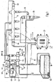
- FIG. 1 a fuel injection device for an internal combustion engine in a schematic representation
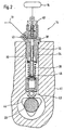
- FIG. 2 a section of the fuel injection device in a section along line II-II in FIG. 1 ,
- a fuel injection device for an internal combustion engine for example of a motor vehicle is shown.
- the internal combustion engine is preferably a self-igniting internal combustion engine and has one or more cylinders.
- the motor vehicle has a fuel tank 10, is stored in the fuel for the operation of the internal combustion engine.
- the fuel injection device has a feed pump 12, is conveyed by the fuel from the fuel tank 10 via a connection 13 to the suction side of several, for example, two high-pressure pumps 14.
- the high pressure pumps 14 deliver fuel into a reservoir 16 which may be tubular, for example, or in any other form. From the memory 16 lead lines 18 to arranged on the cylinders of the internal combustion engine injectors 20 from.
- an electric control valve 22 through which an opening of the injectors 20 is controlled so as to effect fuel injection by the respective injector 20 or prevent fuel injection.
- the control valves 22 are controlled by an electronic control device 23, by the function of operating parameters of the internal combustion engine, such as speed, load, temperature and others, the time and duration of Fuel injection is determined by the injectors 20.
- the high-pressure pumps 14 are mechanically driven by a camshaft 30 of the internal combustion engine and thus proportional to the speed of the internal combustion engine.
- the high-pressure pumps 14 each have a pump housing 32, in which in a cylinder bore 34, a pump piston 36 is tightly guided, which limits a pump working space 38 in the respective cylinder bore 34.
- an outlet valve 40 is arranged in the form of a check valve 16 opening towards the reservoir 16, through which the separation between the pump working chambers 38 and the reservoir 16 takes place during the suction stroke of the pump piston 36.
- an inlet valve 42 in the form of a pump working spaces 38 toward the opening check valve is arranged, through which the separation between the pump working chambers 38 and the feed pump 12 during the delivery stroke of the pump piston 36 ,
- the pump pistons 36 of the high-pressure pumps 14 are driven directly by the camshaft 30 of the internal combustion engine, through which the gas exchange valves of the internal combustion engine are actuated.
- the camshaft 30 in this case has additional cams 44 corresponding to the number of high-pressure pumps 14, through which the pump pistons 36 are driven in a stroke movement.
- the cams 44 are preferably as multiple cams, for example as in FIG. 2 formed as a triple cam, so that each pump piston 36 executes three strokes in one revolution of the camshaft 30. In the case of two high-pressure pumps 14, therefore, six delivery strokes of the pump pistons 36 take place during one revolution of the camshaft 30.
- the pump pistons are based on one Plunger 43; For example, a roller tappet on the cam 44, wherein the system between plunger 43 and cam 44 is ensured by a spring 45.
- the pump pistons 34 As they move radially inward, the pump work spaces 38 are connected to the outlet of the feed pump 12 with the intake valves 42 open and fueled with the pump work spaces 38 separated from the reservoir 16 by the closed exhaust valves 40 are.
- the pump working chambers 38 are connected to the memory 16 with the exhaust valves 40 open and separated from the pressure side of the delivery pump 12 by the closed intake valves 42.
- the fuel injector further includes a fuel metering device 46 disposed between the discharge side of the delivery pump 12 and the suction side of the high pressure pumps 14.
- the fuel metering device 46 is formed for example by an electrically operated proportional valve having an actuator 47, such as an electromagnet or a piezoelectric actuator, and a movable valve member 48 through which a variable flow area is set.
- the actuator 47 is controlled by the control device 23 such that a certain flow area in the connection between the feed pump 12 and the high-pressure pump 14 is adjusted by the valve member 48 of the fuel metering device 46.
- the flow area can be adjusted by the valve member 48 continuously between a maximum flow area and a minimum flow area.
- by the valve member 48 of the flow area are at least approximately completely closed.
- a pressure sensor 49 Connected to the control device 23 is a pressure sensor 49, by which at least indirectly the pressure prevailing in the accumulator 16 is detected and from which an electrical signal for the pressure of the control device 23 is supplied.
- the control device 23 are also supplied with signals for operating conditions of the internal combustion engine from further sensor devices, for example for the rotational speed, the load, the coolant temperature of the internal combustion engine.
- a specific desired value for the pressure in the reservoir 16 is predetermined, wherein a signal for the actual value of the pressure is supplied to the control device 23 by the pressure sensor 49.
- the fuel metering device 46 is actuated by the control device 23 such that this deviation is eliminated.
- the fuel metering device 46 is controlled by the control device 23 such that it sets a larger flow area between the feed pump 12 and the high-pressure pump 14, so that a larger amount of fuel is conveyed into the memory 16 by the high-pressure pumps 14. If the actual value for the pressure in the reservoir 16 is greater than the desired value, then the fuel metering means 46 is controlled by the control device 23 so that it sets a smaller flow area between the feed pump 12 and the high-pressure pump 14, so that by the high-pressure pumps 14 a lower Fuel quantity is conveyed into the memory 16.
- bypass connection 50 which leads to a discharge area than, for example, a leading to the fuel tank 10 return 54 or the suction side of the feed pump 12 can serve.
- an overflow valve 52 opening towards the relief region is arranged, which is a pressure valve which opens when a predetermined pressure is exceeded and releases the bypass connection 50 to the relief region.
- the pressure between the feed pump 12 and the fuel metering device 46 increases and if the opening pressure of the overflow valve 52 is exceeded, fuel flows to the discharge area, then that the pressure between the feed pump 12 and the fuel metering device 46 is limited.
- a further bypass connection 56 to a discharge area from ,. as the turn, the return 54 or the suction side of the feed pump 12 can serve.
- a throttle point 58 is provided in the further bypass connection 56. In certain operating conditions of the internal combustion engine, for example, during overrun, may be promoted by the high-pressure pump 14 no fuel in the memory 16. If the flow area between the feed pump 12 and the high-pressure pumps 14 can not be reliably completely closed by the fuel metering device 46, fuel still passes through the fuel metering device 46. This fuel is discharged via the further bypass connection 58 in the discharge area, so that it is not sucked by the high-pressure pumps 14 and conveyed into the memory 16. By throttling point 58, the amount of fuel flowing to the discharge area is limited.
- the high-pressure pumps 14 are operatively connected in parallel to each other and these promote fuel independently from each other in the memory 16.
- the high-pressure pumps 14 are in each case an opening 60 of a housing 61, which is a crankcase or a cylinder head of the internal combustion engine used.
- the fuel meter 46 is as in FIG FIG. 1 shown separated from the high-pressure pumps 14 arranged.
- the fuel metering device 46, the bypass connection 50 with the overflow valve 52 and the bypass connection 56 with the throttle restriction 58 can likewise be arranged on the housing of the internal combustion engine, in particular its crankcase or cylinder head.
- the feed pump 12 may have its own drive, for example, an electric motor drive, or driven by the internal combustion engine, for example, also by the camshaft 30.
- a fuel filter 62 may be arranged, which may be formed as a pre-filter can.
- a fuel filter 63 may be arranged, which may be formed as a fine filter.
- a pressure regulating valve 64 by which the pressure in the reservoir 16 can be adjusted by controlling a connection to a relief region through which fuel can be removed from the reservoir 16.
- a pressure relief valve by which the pressure in the memory 16 is limited.
Landscapes
- Engineering & Computer Science (AREA)
- Chemical & Material Sciences (AREA)
- Combustion & Propulsion (AREA)
- Mechanical Engineering (AREA)
- General Engineering & Computer Science (AREA)
- Fuel-Injection Apparatus (AREA)
Claims (7)
- Installation d'injection de carburant pour un moteur à combustion interne comportant plusieurs pompes haute pression (14) amenant le carburant à un accumulateur (16) et présentant un piston de pompe (36) entraîné dans un mouvement linéaire par un arbre à cames (30), une pompe d'alimentation (12) amenant le carburant d'un réservoir de carburant (10) aux pompes haute pression (14), les injecteurs (20) injectant le carburant dans les cylindres du moteur à combustion interne étant reliés à l'accumulateur (16), avec entre la pompe d'alimentation (12) et les pompes haute pression (14) une seule installation de dosage de carburant (46) pour régler l'alimentation en carburant de la pompe d'alimentation (12) aux pompes haute pression (14) de sorte qu'une quantité de carburant nécessaire pour maintenir dans l'accumulateur (16) une pression prédéfinie est transportée par les pompes haute pression (14) dans l'accumulateur (16), chaque pompe haute pression (14) présentant, dans sa liaison avec le côté de refoulement de la pompe d'alimentations (12), une soupape d'admission (42) sous la forme d'une soupape de retenue,
caractérisée en ce que
l'arbre à cames (30) qui actionne aussi les soupapes d'échange gazeux du moteur à combustion interne est un arbre à cames du moteur à combustion interne, en ce que les pompes haute pression (14) sont insérées chacune dans une ouverture (60) d'un carter de vilebrequin (61) ou d'une culasse (61) du moteur à combustion interne, et en ce que l'installation de dosage de carburant (46) est disposée sur le carter de vilebrequin (61) ou la culasse (61) du moteur à combustion interne, en étant séparée des pompes haute pression (14). - Installation d'injection de carburant selon la revendication 1,
caractérisée en ce que
l'installation de dosage de carburant (46) règle une section transversale d'écoulement variable dans la liaison (13) entre la pompe d'alimentation (12) et les pompes haute pression (14). - Installation d'injection de carburant selon la revendication 1 ou 2,
caractérisée en ce que
l'installation de dosage de carburant (46) est commandée par une unité de commande électronique (23) reliée à un ensemble de capteurs (49) saisissant la pression dans l'accumulateur (16). - Installation d'injection de carburant selon l'une quelconque des revendications 1 à 3,
caractérisée en ce qu'
un raccord de dérivation (50) actionné par une soupape de surpression (52) qui libère le raccord de dérivation (50) lors du dépassement d'une pression prédéfinie, évacue vers une zone de décharge (54) entre la pompe d'alimentation (12) et les pompes haute pression (14). - Installation d'injection de carburant selon l'une quelconque des revendications 1 à 4,
caractérisée en ce qu'
un raccord de dérivation (50) comportant un point d'étranglement (58) dévie vers une zone de décharge (54) entre la pompe d'alimentation (12) et les pompes haute pression (14). - Installation d'injection de carburant selon la revendication 4 ou 5,
caractérisée en ce que
la soupape de surpression (52) et/ou le point d'étranglement (58) sont montés sur un boîtier, de préférence un carter de vilebrequin du moteur à combustion interne. - Moteur à combustion interne comportant une installation d'injection de carburant selon l'une quelconque des revendications précédentes,
caractérisée en ce que
l'arbre à cames (30) du moteur à combustion interne présente une came multiple (44) pour l'entraînement du piston de pompe (36) des pompes haute pression (14).
Applications Claiming Priority (3)
| Application Number | Priority Date | Filing Date | Title |
|---|---|---|---|
| DE2002137586 DE10237586A1 (de) | 2002-08-16 | 2002-08-16 | Kraftstoffeinspritzeinrichtung für eine Brennkraftmaschine |
| DE10237586 | 2002-08-16 | ||
| PCT/DE2003/000880 WO2004018867A1 (fr) | 2002-08-16 | 2003-03-18 | Dispositif d'injection de carburant d'une machine a combustion interne |
Publications (3)
| Publication Number | Publication Date |
|---|---|
| EP1530681A1 EP1530681A1 (fr) | 2005-05-18 |
| EP1530681B1 EP1530681B1 (fr) | 2007-07-11 |
| EP1530681B2 true EP1530681B2 (fr) | 2018-09-26 |
Family
ID=30775345
Family Applications (1)
| Application Number | Title | Priority Date | Filing Date |
|---|---|---|---|
| EP03720202.5A Expired - Lifetime EP1530681B2 (fr) | 2002-08-16 | 2003-03-18 | Dispositif d'injection de carburant d'une machine a combustion interne |
Country Status (4)
| Country | Link |
|---|---|
| EP (1) | EP1530681B2 (fr) |
| CN (1) | CN100532804C (fr) |
| DE (2) | DE10237586A1 (fr) |
| WO (1) | WO2004018867A1 (fr) |
Families Citing this family (10)
| Publication number | Priority date | Publication date | Assignee | Title |
|---|---|---|---|---|
| DE10343480A1 (de) * | 2003-09-19 | 2005-04-14 | Robert Bosch Gmbh | Kraftstoffeinspritzeinrichtung für eine Brennkraftmaschine |
| ES2283163B1 (es) * | 2004-03-22 | 2008-08-01 | Emiliano Lopez Cano Toribio | Aplicacion de motores diesel a motocicletas. |
| JP5195451B2 (ja) * | 2008-04-15 | 2013-05-08 | 株式会社デンソー | 燃料噴射装置、それに用いられる蓄圧式燃料噴射装置システム |
| SE534873C2 (sv) * | 2010-06-22 | 2012-01-31 | Scania Cv Ab | Bränslesystem för insprutning av en bränsleblandning i en förbränningsmotor |
| DE102011007686A1 (de) | 2011-04-19 | 2012-10-25 | Robert Bosch Gmbh | Kraftstofffördereinrichtung für eine Kraftstoffeinspritzeinrichtung einer Brennkraftmaschine |
| FI123271B (fi) * | 2011-06-23 | 2013-01-31 | Waertsilae Finland Oy | Polttoaineen ruiskutusjärjestelmä |
| DE102011089972A1 (de) * | 2011-12-27 | 2013-06-27 | Robert Bosch Gmbh | Kraftstoffüberströmventil für eine Kraftstoffeinspritzeinrichtung und Kraftstoffeinspritzeinrichtung mit Kraftstoffüberströmventil |
| US9394857B2 (en) * | 2012-01-03 | 2016-07-19 | Volvo Lastvagnar Ab | Fuel system and corresponding method |
| JP5672287B2 (ja) * | 2012-10-11 | 2015-02-18 | 株式会社デンソー | 燃料噴射装置 |
| DE102018216176A1 (de) * | 2018-09-21 | 2020-03-26 | Robert Bosch Gmbh | Kraftstofffördereinrichtung für eine Brennkraftmaschine |
Citations (3)
| Publication number | Priority date | Publication date | Assignee | Title |
|---|---|---|---|---|
| DE4233273A1 (de) † | 1992-01-16 | 1993-09-02 | Diesel Tech Corp | Kraftstoffeinspritzanlage mit gemeinsamer druckleitung |
| DE19508445A1 (de) † | 1995-03-09 | 1996-09-12 | Kloeckner Humboldt Deutz Ag | Kraftstoffeinspritzvorrichtung für eine selbstzündende Brennkraftmaschine |
| EP1298316A2 (fr) † | 2001-09-26 | 2003-04-02 | DEUTZ Aktiengesellschaft | Système d'injection de carburant |
Family Cites Families (6)
| Publication number | Priority date | Publication date | Assignee | Title |
|---|---|---|---|---|
| WO1994027039A1 (fr) * | 1993-05-06 | 1994-11-24 | Cummins Engine Company, Inc. | Pompe a haute pression a deplacement variable s'utilisant dans des systemes d'injection de carburant comportant un rail commun |
| JPH08135462A (ja) * | 1994-11-09 | 1996-05-28 | Yamaha Motor Co Ltd | 縦型エンジン |
| DE19630938C5 (de) * | 1996-07-31 | 2008-02-14 | Siemens Ag | Kraftstoffzuleitung mit einem Volumenstromregelventil und Volumenstromregelventil |
| WO2000011342A1 (fr) * | 1998-08-25 | 2000-03-02 | Siemens Aktiengesellschaft | Procede permettant la montee rapide de la pression de carburant dans un accumulateur de carburant |
| DE19846157A1 (de) * | 1998-10-07 | 2000-04-13 | Bosch Gmbh Robert | Pumpenanordnung zur Kraftstoffhochdruckerzeugung |
| JP3851056B2 (ja) * | 2000-04-18 | 2006-11-29 | トヨタ自動車株式会社 | 高圧ポンプ |
-
2002
- 2002-08-16 DE DE2002137586 patent/DE10237586A1/de not_active Withdrawn
-
2003
- 2003-03-18 WO PCT/DE2003/000880 patent/WO2004018867A1/fr not_active Ceased
- 2003-03-18 DE DE50307660T patent/DE50307660D1/de not_active Expired - Lifetime
- 2003-03-18 CN CNB038193752A patent/CN100532804C/zh not_active Expired - Lifetime
- 2003-03-18 EP EP03720202.5A patent/EP1530681B2/fr not_active Expired - Lifetime
Patent Citations (3)
| Publication number | Priority date | Publication date | Assignee | Title |
|---|---|---|---|---|
| DE4233273A1 (de) † | 1992-01-16 | 1993-09-02 | Diesel Tech Corp | Kraftstoffeinspritzanlage mit gemeinsamer druckleitung |
| DE19508445A1 (de) † | 1995-03-09 | 1996-09-12 | Kloeckner Humboldt Deutz Ag | Kraftstoffeinspritzvorrichtung für eine selbstzündende Brennkraftmaschine |
| EP1298316A2 (fr) † | 2001-09-26 | 2003-04-02 | DEUTZ Aktiengesellschaft | Système d'injection de carburant |
Also Published As
| Publication number | Publication date |
|---|---|
| CN1675463A (zh) | 2005-09-28 |
| EP1530681B1 (fr) | 2007-07-11 |
| WO2004018867A1 (fr) | 2004-03-04 |
| DE10237586A1 (de) | 2004-02-26 |
| CN100532804C (zh) | 2009-08-26 |
| EP1530681A1 (fr) | 2005-05-18 |
| DE50307660D1 (de) | 2007-08-23 |
Similar Documents
| Publication | Publication Date | Title |
|---|---|---|
| EP1476654B1 (fr) | Dispositif d'injection de carburant pour moteur a combustion interne | |
| EP1537325B1 (fr) | Dispositif d'injection de carburant pour moteur a combustion interne | |
| EP3292289B1 (fr) | Procédé de fonctionnement d'un dispositif d'injection d'eau pour un moteur à combustion interne | |
| DE4401074B4 (de) | Pumpenanordnung, insbesondere zur Förderung von Kraftstoff aus einem Vorratsbehälter zu einer Brennkraftmaschine | |
| EP2032832B1 (fr) | Dispositif d'injection de carburant pour un moteur à combustion interne | |
| EP1296060B1 (fr) | Système d'injection de carburant pour un moteur à combustion interne | |
| EP1357285A2 (fr) | Dispositif d'injection de carburant pour un moteur à combustion interne | |
| EP1476656B1 (fr) | Dispositif d'injection de carburant pour un moteur a combustion interne | |
| DE19832287A1 (de) | Nadelgesteuerte Kraftstoffinjektoreinheit | |
| WO2005038237A1 (fr) | Systeme d'injection de carburant pour un moteur a combustion interne | |
| EP1530681B2 (fr) | Dispositif d'injection de carburant d'une machine a combustion interne | |
| DE10215021A1 (de) | Kraftstoffeinspritzeinrichtung für eine Brennkraftmaschine | |
| DE10156408B4 (de) | Kraftstoffeinspritzeinrichtung für eine Brennkraftmaschine | |
| EP1357283B1 (fr) | Dispositif d'injection de carburant pour un moteur à combustion interne | |
| DE10244551A1 (de) | Kraftstoffeinspritzeinrichtung für eine Brennkraftmaschine | |
| DE102005033638A1 (de) | Kraftstoff-Fördereinrichtung, insbesondere für eine Brennkraftmaschine | |
| EP1595074B1 (fr) | Systeme d'injection de carburant pour moteur a combustion interne | |
| DE10139055A1 (de) | Verfahren, Computerprogramm, Steuer- und/oder Regelgerät sowie Kraftstoffsystem für eine Brennkraftmaschine | |
| EP1389683B1 (fr) | Dispositif d'injection de carburant pour un moteur à combustion interne | |
| EP1361359B1 (fr) | Dispositif d'injection de carburant pour moteurs à combustion interne | |
| EP1537334B1 (fr) | Pompe, notamment pour un systeme d'injection de carburant destine a un moteur a combustion interne | |
| WO2005038236A1 (fr) | Systeme d'injection de carburant pour un moteur a combustion interne | |
| DE102007004605B4 (de) | Hochdruckpumpe und Einspritzanlage für eine Brennkraftmaschine mit einer Hochdruckpumpe | |
| DE10205811A1 (de) | Kraftstoffeinspritzeinrichtung für eine Brennkraftmaschine | |
| DE102004039745A1 (de) | Kraftstoffeinspritzeinrichtung für einen Zylinder einer Brennkraftmaschine |
Legal Events
| Date | Code | Title | Description |
|---|---|---|---|
| PUAI | Public reference made under article 153(3) epc to a published international application that has entered the european phase |
Free format text: ORIGINAL CODE: 0009012 |
|
| 17P | Request for examination filed |
Effective date: 20050316 |
|
| AK | Designated contracting states |
Kind code of ref document: A1 Designated state(s): AT BE BG CH CY CZ DE DK EE ES FI FR GB GR HU IE IT LI LU MC NL PT RO SE SI SK TR |
|
| RBV | Designated contracting states (corrected) |
Designated state(s): CZ DE FR GB SE |
|
| GRAP | Despatch of communication of intention to grant a patent |
Free format text: ORIGINAL CODE: EPIDOSNIGR1 |
|
| GRAS | Grant fee paid |
Free format text: ORIGINAL CODE: EPIDOSNIGR3 |
|
| GRAA | (expected) grant |
Free format text: ORIGINAL CODE: 0009210 |
|
| AK | Designated contracting states |
Kind code of ref document: B1 Designated state(s): CZ DE FR GB SE |
|
| REG | Reference to a national code |
Ref country code: GB Ref legal event code: FG4D Free format text: NOT ENGLISH |
|
| REF | Corresponds to: |
Ref document number: 50307660 Country of ref document: DE Date of ref document: 20070823 Kind code of ref document: P |
|
| REG | Reference to a national code |
Ref country code: SE Ref legal event code: TRGR |
|
| GBT | Gb: translation of ep patent filed (gb section 77(6)(a)/1977) |
Effective date: 20070920 |
|
| ET | Fr: translation filed | ||
| PLBI | Opposition filed |
Free format text: ORIGINAL CODE: 0009260 |
|
| 26 | Opposition filed |
Opponent name: DEUTZ AKTIENGESELLSCHAFT Effective date: 20080404 |
|
| PLAX | Notice of opposition and request to file observation + time limit sent |
Free format text: ORIGINAL CODE: EPIDOSNOBS2 |
|
| PLAF | Information modified related to communication of a notice of opposition and request to file observations + time limit |
Free format text: ORIGINAL CODE: EPIDOSCOBS2 |
|
| PLBB | Reply of patent proprietor to notice(s) of opposition received |
Free format text: ORIGINAL CODE: EPIDOSNOBS3 |
|
| APBM | Appeal reference recorded |
Free format text: ORIGINAL CODE: EPIDOSNREFNO |
|
| APBP | Date of receipt of notice of appeal recorded |
Free format text: ORIGINAL CODE: EPIDOSNNOA2O |
|
| APAH | Appeal reference modified |
Free format text: ORIGINAL CODE: EPIDOSCREFNO |
|
| APBQ | Date of receipt of statement of grounds of appeal recorded |
Free format text: ORIGINAL CODE: EPIDOSNNOA3O |
|
| PGFP | Annual fee paid to national office [announced via postgrant information from national office to epo] |
Ref country code: CZ Payment date: 20150306 Year of fee payment: 13 |
|
| PGFP | Annual fee paid to national office [announced via postgrant information from national office to epo] |
Ref country code: SE Payment date: 20150324 Year of fee payment: 13 Ref country code: GB Payment date: 20150324 Year of fee payment: 13 |
|
| REG | Reference to a national code |
Ref country code: FR Ref legal event code: PLFP Year of fee payment: 14 |
|
| REG | Reference to a national code |
Ref country code: SE Ref legal event code: EUG |
|
| GBPC | Gb: european patent ceased through non-payment of renewal fee |
Effective date: 20160318 |
|
| PG25 | Lapsed in a contracting state [announced via postgrant information from national office to epo] |
Ref country code: SE Free format text: LAPSE BECAUSE OF NON-PAYMENT OF DUE FEES Effective date: 20160319 Ref country code: CZ Free format text: LAPSE BECAUSE OF NON-PAYMENT OF DUE FEES Effective date: 20160318 |
|
| PG25 | Lapsed in a contracting state [announced via postgrant information from national office to epo] |
Ref country code: GB Free format text: LAPSE BECAUSE OF NON-PAYMENT OF DUE FEES Effective date: 20160318 |
|
| REG | Reference to a national code |
Ref country code: FR Ref legal event code: PLFP Year of fee payment: 15 |
|
| PGFP | Annual fee paid to national office [announced via postgrant information from national office to epo] |
Ref country code: FR Payment date: 20170323 Year of fee payment: 15 |
|
| APBU | Appeal procedure closed |
Free format text: ORIGINAL CODE: EPIDOSNNOA9O |
|
| PUAH | Patent maintained in amended form |
Free format text: ORIGINAL CODE: 0009272 |
|
| STAA | Information on the status of an ep patent application or granted ep patent |
Free format text: STATUS: PATENT MAINTAINED AS AMENDED |
|
| 27A | Patent maintained in amended form |
Effective date: 20180926 |
|
| AK | Designated contracting states |
Kind code of ref document: B2 Designated state(s): CZ DE FR GB SE |
|
| REG | Reference to a national code |
Ref country code: DE Ref legal event code: R102 Ref document number: 50307660 Country of ref document: DE |
|
| PG25 | Lapsed in a contracting state [announced via postgrant information from national office to epo] |
Ref country code: FR Free format text: LAPSE BECAUSE OF NON-PAYMENT OF DUE FEES Effective date: 20180331 |
|
| PGFP | Annual fee paid to national office [announced via postgrant information from national office to epo] |
Ref country code: DE Payment date: 20220525 Year of fee payment: 20 |
|
| REG | Reference to a national code |
Ref country code: DE Ref legal event code: R071 Ref document number: 50307660 Country of ref document: DE |