EP1530664B1 - Underwater cleaner - Google Patents
Underwater cleaner Download PDFInfo
- Publication number
- EP1530664B1 EP1530664B1 EP04737357A EP04737357A EP1530664B1 EP 1530664 B1 EP1530664 B1 EP 1530664B1 EP 04737357 A EP04737357 A EP 04737357A EP 04737357 A EP04737357 A EP 04737357A EP 1530664 B1 EP1530664 B1 EP 1530664B1
- Authority
- EP
- European Patent Office
- Prior art keywords
- suction
- water jet
- nozzle
- jet nozzle
- underwater cleaner
- Prior art date
- Legal status (The legal status is an assumption and is not a legal conclusion. Google has not performed a legal analysis and makes no representation as to the accuracy of the status listed.)
- Expired - Lifetime
Links
- XLYOFNOQVPJJNP-UHFFFAOYSA-N water Substances O XLYOFNOQVPJJNP-UHFFFAOYSA-N 0.000 claims abstract description 98
- 230000009182 swimming Effects 0.000 claims abstract description 22
- 238000004140 cleaning Methods 0.000 abstract description 7
- 239000002245 particle Substances 0.000 abstract description 7
- 230000000694 effects Effects 0.000 description 12
- 238000009331 sowing Methods 0.000 description 10
- 239000012535 impurity Substances 0.000 description 6
- 239000000356 contaminant Substances 0.000 description 5
- 239000012530 fluid Substances 0.000 description 4
- 238000011109 contamination Methods 0.000 description 2
- 238000009434 installation Methods 0.000 description 1
- 238000004519 manufacturing process Methods 0.000 description 1
- 239000004576 sand Substances 0.000 description 1
- 238000007789 sealing Methods 0.000 description 1
- 239000002689 soil Substances 0.000 description 1
- 239000007787 solid Substances 0.000 description 1
- 238000003756 stirring Methods 0.000 description 1
Images


Classifications
-
- E—FIXED CONSTRUCTIONS
- E04—BUILDING
- E04H—BUILDINGS OR LIKE STRUCTURES FOR PARTICULAR PURPOSES; SWIMMING OR SPLASH BATHS OR POOLS; MASTS; FENCING; TENTS OR CANOPIES, IN GENERAL
- E04H4/00—Swimming or splash baths or pools
- E04H4/14—Parts, details or accessories not otherwise provided for
- E04H4/16—Parts, details or accessories not otherwise provided for specially adapted for cleaning
- E04H4/1618—Hand-held powered cleaners
- E04H4/1636—Suction cleaners
Definitions
- the invention relates to an underwater cleaner, in particular for a swimming pool, with a suction nozzle housing with a suction nozzle communicating with a suction nozzle and a Sauggabe defining suction mouth, from the suction chamber emanates an outlet channel, to which a filter device is connected, with an opening into the suction water jet nozzle, via which water under pressure in the suction chamber is fed so that under the principle of the water jet pump in the suction chamber, a negative pressure, wherein the water jet nozzle opens in the suction nozzle in the suction chamber, and wherein the distance between the water jet nozzle and the Saugroe is less than that smallest inner width of the outlet channel.
- swimming pool vacuum cleaner for cleaning swimming pools.
- Such devices are disclosed, for example, by US 5,317,776 A, US 5,842,243 A, US 6,119,293 A or US 6,473,927 B1.
- the disadvantage is that these known pool vacuum cleaners are relatively bulky, require a certain lead time and / or are cumbersome to handle.
- the US 5,450,644 A shows a battery-powered underwater cleaner, which sucks water via a pump through a suction nozzle and a filter.
- the designed as a radial pump pump is arranged between the suction nozzle and filter.
- the US 4,962,559 A describes a wireless swimming pool vacuum cleaner, in which sucked through a pump through the suction nozzle and a filter water and fed back to the swimming pool.
- the filter is arranged between the suction nozzle and the pump.
- suction pumps suction, wireless underwater cleaners have the disadvantage of low suction, so that massive contaminants, such as sand, soil, pebbles can be sucked only insufficient.
- Pool vacuum cleaners with a higher suction capacity are not suitable for cleaning even hard-to-reach areas such as steps or corners of a swimming pool.
- FR 2 715 960 A1 discloses an underwater cleaner for a swimming pool, wherein a water jet nozzle opens into a suction space.
- the mouth of the water jet nozzle is arranged relatively far from the sowing level. Massive impurities can not or only with difficulty be removed with this underwater vacuum cleaner.
- DE 950 964 C describes an underwater vacuum cleaner, which has a water jet nozzle opening into a suction chamber and which includes all features of the preamble of claim 1.
- the water flowing through the filter is returned to the suction chamber via the water jet nozzle, the water jet nozzle being directed against the floor.
- dirt particles can be released by the water jet nozzle directed towards the bottom, there is a risk that they will be moved back into the swimming pool through the suction mouth, so that the pool can not be re-contaminated.
- a battery-powered pool vacuum cleaner in which water is drawn in together with contaminants by means of a suction nozzle and conveyed into a filter according to the principle of the water jet pump. Since the water jet nozzle opens into the suction chamber at a relatively large distance from the suction nozzle, massier dirt particles can not or only with difficulty be removed.
- the water jet nozzle is supplied by a submersible pump, which removes water at the highest point of the suction chamber via a sieve. This has the disadvantage that when starting the pool vacuum cleaner submersible pump relatively long promotes only air, because, the suction chamber is previously flooded manually. In any case, commissioning is difficult.
- the minimum depth of use is determined by the relatively large distance between the intake opening of the submersible pump and the surface to be cleaned. By sucking the water from the suction chamber there is a risk that particles clog the screen very quickly.
- a suction nozzle for a pool vacuum cleaner is known, is sucked in the polluted water according to the principle of water jet or Venturi pump.
- a water hose of an external water pressure source can be connected to the suction nozzle. Due to the water flowing into the suction chamber via the water jet nozzle, a negative pressure is created in the suction chamber, so that polluted water is sucked in via the suction nozzle.
- the disadvantage is that even with this suction nozzle only relatively light and low-mass soiling can be removed.
- a swimming pool cleaner which has a manifold for pressurized supplied water, from which branches off a number of Fegeschläuchen over which contaminants are fluidized.
- From the manifold lead further jet nozzles in the designed as Venturi chamber suction chamber of the pool cleaner, the jet nozzles are arranged distributed around the circumference of the suction nozzle.
- water jet principle water is sucked in from the area of the bottom of the swimming pool and led to a filter. Since the jet nozzles in Lead away substantially from the sowing level at an angle of about 90 °, with this no impurities on the pool floor can be torn away. This function must be taken over by the hoses.
- This pool cleaner is complex, voluminous and relatively unwieldy in the application. In addition, a high water flow rate and thus a pump with high flow rate is needed.
- FR 2 667 099 A1 discloses a pool vacuum cleaner, wherein two water jet nozzles open tangentially in a suction chamber and generate a swirl flow.
- the water jet nozzles are directed to the sowing level, wherein the fluid line of the water jet nozzles with the sow level an angle ⁇ 0 ° span.
- the flow rate through the water jet principle is relatively low due to the flow-unfavorable arrangement.
- the water jet nozzles the dirt is whirled up, so that a back pollution of the swimming pool by stray dirt particles can not be excluded.
- Another disadvantage is that two water jet nozzles are required, whereby a pump with a relatively high flow rate must be provided.
- the object of the invention is to avoid these disadvantages and to increase the cleaning performance for underwater cleaner of the type mentioned in the simplest possible way.
- the underwater cleaner should be as small as possible and handy to allow easy cleaning of steps or corners in a swimming pool.
- this is achieved in that the water jet nozzle is directed away from the sowing level and that a fluid line of the water jet nozzle in the region of the mouth into the suction chamber with the sowing level an angle> 0 ° and ⁇ 45 °, includes.
- the distance between the water jet nozzle and the suction level corresponds to a maximum of two-thirds of the smallest inner width, preferably at most half the smallest inner width of the outlet channel.
- the distance between the water jet nozzle and the suction level is less than half the maximum height of the suction chamber.
- the distance between the water jet nozzle and the sowing level is a maximum of 7 cm, preferably a maximum of 2.5 cm to 3 cm.
- the water jet opens as close as possible to the suction level in the suction chamber. This causes the dirt particles directly from the water jet be flowed and torn away in the direction of the outlet channel, so that even massive dirt particles, which could not be removed by the mere suction alone, can be solved from the bottom of the swimming pool and transported into the filter. The removal of impurities thus takes place by a combination of suction and pressure effect of the water jet.
- the water jet nozzle opens on a side opposite the outlet channel side into the suction chamber, wherein it is preferably provided that the water jet nozzle is directed into the outlet channel, with particular preferably the fluid line with the axis of the outlet channel an angle smaller than 180 ° , preferably between 150 ° and 170 °.
- a particularly good suction power can be achieved when the axis of the outlet channel to the sowing level by an angle between 0 ° and 45 °, preferably between 10 ° and 15 °, is inclined.
- the inner width of the suction nozzle is preferably slightly smaller than the width of the outlet channel. As a result, high flow speeds can be achieved in the area of the suction nozzle, which supports the cleaning effect.
- the angle between the fluid line of the water jet nozzle and the suction level is preferably ⁇ 25 °, particularly preferably ⁇ 15 °.
- a water hose connected to an external pressure source can be connected to the water jet nozzle.
- this does not always have the desired side effect that additional water is supplied to the pool and the volume of water in the pool rises.
- This side effect can be avoided if the underwater cleaner has an integrated, preferably battery-operated submersible pump whose discharge nozzle is fluidly connected to the water jet nozzle.
- the suction opening of the submersible pump is arranged outside the suction space, preferably outside the suction nozzle housing, and is hydraulically separated from the suction space.
- the suction opening is arranged in the region of the suction level, wherein preferably the distance between the suction opening and the suction level is less than the maximum height, particularly preferably less than half the maximum height of the suction space. Due to this relatively low installation position of the suction opening of the underwater cleaner can be used even at low water levels. Since the submersible pump water not directly from the suction chamber, but outside of the suction takes directly from the pool, the commissioning of the underwater cleaner is straightforward, because on the suction side of the submersible pump air-filled spaces are avoided.
- the outlet channel and the filter device is arranged on the user-facing side actuation of the suction nozzle housing.
- the filter device and the outlet channel are arranged on the actuation side, on the side opposite the actuation side, the free view of contamination obstructing projections are avoided, so that the user can perform the underwater cleaner very precisely on the dirt to be removed on the operating rod.
- the suction nozzle is at least partially framed on its suction side facing the suction-absorbing body of the suction mouth forming rubber lips or brushes.
- the rubber lips or the brushes compensate for unevenness in the swimming pool floor, so that the full suction effect is guaranteed even for depressions, elevations or roughness of swimming pool floors.
- the submersible pump is connected via a preferably designed as a spiral channel power cable with a battery case.
- the battery case can preferably be connected via a rubber strap releasably connected to an actuating rod.
- the submersible pump and / or the battery housing is integrated in the suction nozzle housing.
- the underwater cleaner 1 has a suction nozzle housing 3 forming a suction nozzle 2, which comprises a suction chamber 4. From the suction chamber 4 assumes an outlet channel 5, to which a filter device 6 is connected.
- the underwater cleaner 1 works on the water jet pump principle.
- the pressure source is a submersible pump 10 which is integrated in the suction nozzle housing 3 and whose discharge nozzle 9 is flow-connected to the water jet nozzle 7 via a connecting line 8.
- the suction opening 11 of the submersible pump 10 is located outside the suction nozzle housing 3 in the bottom area of the underwater cleaner 1 near the suction level 16 defined by the suction mouth 19, wherein a sieve 12 is provided in the area of the suction opening 11 is arranged to prevent coarse contamination.
- the distance between the suction port 11 and the sowing level 16 of the underwater cleaner 1 is substantially less than the maximum height H of the suction chamber 4.
- a sharp jet of water is supplied to the suction chamber 4, which generates a negative pressure in the suction chamber 4, sucked through the suction nozzle 2 contaminated water and finally into the filter device. 6 is transported. The water passes through the filter device 6 and is then returned to the swimming pool.
- the water jet nozzle 7 is arranged as close as possible to the suction level 16.
- the distance h between the mouth of the water jet nozzle 7 and the sowing level 16 is less than half the internal width b of the outlet channel 5 and, for example, less than 7 cm, preferably less than 3 cm is. This ensures that even more massive impurities, such as smaller and medium pebbles 14 can be removed from the body to be cleaned 15, for example, from the bottom of a swimming pool, since the pebbles 14 are torn away from the water jet and pressed in the direction of the outlet channel 5.
- the effect of the underwater cleaner 1 is thus based on a combination of suction and pressure effect according to the inflowing into the suction chamber 4 water jet, which is indicated by the arrow S in Fig. 2.
- the best suction effect is achieved when in operation the sowing level 16 coincides with the level of the body 15 to be cleaned.
- the water jet nozzle 7 In the mouth region in the suction chamber 4, the water jet nozzle 7 should be inclined slightly upwards in the direction of the outlet channel 5 in order to allow a particularly rapid removal of the contaminants into the filter device 6. If the angle ⁇ , in the bottom region of the Saugdüsengephases 3 on the other hand, spanned by the center line 7 'in the mouth region of the water jet nozzle 7 in the suction chamber 4 on the one hand and with the body 15 to be cleaned during operation of the underwater cleaner 1 approximately parallel trained Saubiee 16, at most 45 °, preferably at most 25 °, particularly preferably at most 15 °, so that the direction indicated by the arrow S in Fig. 2 water jet flows in the direction of the outlet channel 5, a rapid removal of impurities in the filter device 6 is made possible.
- the suction nozzle 2 In order to increase the suction effect of the suction nozzle 2, the suction nozzle 2 is surrounded by the suction mouth 19 forming rubber lips or brush 17. As a result, an excellent suction effect can be achieved even with an uneven body 15.
- the underwater cleaner 1 can be guided over the swimming pool floor 15 via an actuating rod 18 which is attached to the suction nozzle housing 3 at a rigid angle, for example telescopically extendable. Since the filter device 6 is arranged on the user-facing actuator side A, the user has a clear view of lying in the direction of the underwater cleaner 1 still to be cleaned body 15 and thus can quickly detect impurities to be sucked and the underwater cleaner 1, for example, in otherwise difficult to reach corners or in the area of steps of a swimming pool.
- Figures 4 to 6 show a second embodiment, in which the outlet opening 11 of the submersible pump 10 is higher than that of the discharge nozzle 9 is arranged in a lateral region of the underwater cleaner 1.
- the submersible pump 10 is attached via mounting brackets 20 on the suction nozzle housing 3. This allows a very cost-effective production.
- the outlet opening 11 remote from the suction level 16 has the advantage that relatively pure water flows through the dew pump 10 and laying of the screen 12 is hardly to be expected.
- the submersible pump 10 is connected to the battery housing 13 via a cable 21 designed as a spiral channel.
- the battery case 13 is detachably attached to the actuating rod 18 via rubber bands (not shown).
- the connector 22 of the cable 21 on the battery case 13 is secured against unintentional loosening.
- FIGS. 7 to 9 show a further embodiment of an underwater cleaner, wherein the submersible pump 10 and the battery housing 13 are integrated into the suction nozzle housing 3.
- Reference numeral 23 denotes a terminal for a charging connector for the battery.
- the electrical Anatician 23 is, for example, by a screwed cap over the surrounding water sealed.
- Reference numeral 24 denotes a sealing area in which electrical parts such as battery case 13, lines and electrical terminal 23 are sealed against water.
- the underwater cleaner 1 can be switched on via switch, water sensor or magnetic switch.
- the underwater cleaner 1 may still have a special covering, for example an animal form.
- the combined suction and pressure principle applied to the underwater cleaner 1 for releasing and removing the contaminants makes it possible to dimension the submersible pump 10 to be very small and to design the underwater cleaner 1 very compactly and easily.
- the water jet nozzle 7 via the connecting line 8 instead of the submersible pump 10 with an external source of water pressure, for example, connected to a water pipe hose connected.
- an external source of water pressure for example, connected to a water pipe hose connected.
- additional water is introduced into the swimming pool, which is not always desirable.
Landscapes
- Engineering & Computer Science (AREA)
- Architecture (AREA)
- Civil Engineering (AREA)
- Structural Engineering (AREA)
- Structures Of Non-Positive Displacement Pumps (AREA)
- Organic Low-Molecular-Weight Compounds And Preparation Thereof (AREA)
- Nozzles For Electric Vacuum Cleaners (AREA)
Abstract
Description
Die Erfindung betrifft einen Unterwasserreiniger, insbesondere für ein Schwimmbad, mit einem Saugdüsengehäuse mit einer mit einem Saugraum kommunizierenden Saugdüse und einem eine Saugebene definierenden Saugmund, wobei vom Saugraum ein Austrittskanal ausgeht, an welchen eine Filtereinrichtung angeschlossen ist, mit einer in den Saugraum mündenden Wasserstrahldüse, über welche Wasser unter Druck in den Saugraum so zuführbar ist, dass nach dem Prinzip der Wasserstrahlpumpe im Saugraum ein Unterdruck entsteht, wobei die Wasserstrahldüse im Bereich der Saugdüse in den Saugraum einmündet, und wobei der Abstand zwischen der Wasserstrahldüse und der Saugebene geringer ist als die kleinste innere Breite des Austrittskanals.The invention relates to an underwater cleaner, in particular for a swimming pool, with a suction nozzle housing with a suction nozzle communicating with a suction nozzle and a Sauggabe defining suction mouth, from the suction chamber emanates an outlet channel, to which a filter device is connected, with an opening into the suction water jet nozzle, via which water under pressure in the suction chamber is fed so that under the principle of the water jet pump in the suction chamber, a negative pressure, wherein the water jet nozzle opens in the suction nozzle in the suction chamber, and wherein the distance between the water jet nozzle and the Saugebene is less than that smallest inner width of the outlet channel.
Es ist bekannt, Schwimmbadstaubsauger zur Reinigung von Schwimmbecken einzusetzen. Derartige Vorrichtungen werden etwa durch die US 5,317,776 A, die US 5,842,243 A, die US 6,119,293 A oder die US 6,473,927 B1 geoffenbart. Nachteilig ist, dass diese bekannten Schwimmbadstaubsauger relativ unhandlich sind, eine gewisse Vorlaufzeit benötigen und/oder umständlich in der Handhabung sind.It is known to use swimming pool vacuum cleaner for cleaning swimming pools. Such devices are disclosed, for example, by US 5,317,776 A, US 5,842,243 A, US 6,119,293 A or US 6,473,927 B1. The disadvantage is that these known pool vacuum cleaners are relatively bulky, require a certain lead time and / or are cumbersome to handle.
Die US 5,450,644 A zeigt einen batteriebetriebenen Unterwasserreiniger, welcher Wasser über eine Pumpe durch eine Saugdüse ansaugt und einem Filter zuführt. Die als Radialpumpe ausgeführte Pumpe ist dabei zwischen Saugdüse und Filter angeordnet. Die US 4,962,559 A beschreibt einen kabellosen Schwimmbadstaubsauger, bei welchem über eine Pumpe durch die Saugdüse und einen Filter Wasser abgesaugt und wieder dem Schwimmbad zugeführt wird. Der Filter ist dabei zwischen Saugdüse und Pumpe angeordnet. Derartige bekannte, über Saugpumpen ansaugende, kabellose Unterwasserreiniger haben den Nachteil einer geringen Saugleistung, so dass massereiche Verunreinigungen, wie beispielsweise Sand, Erde, Kiesel nur unzureichend abgesaugt werden können. Schwimmbadstaubsauger mit höherer Saugleistung wiederum sind von den Abmessungen her nicht geeignet, um auch schwer zugängliche Stellen wie Stufen oder Ecken eines Schwimmbades zu reinigen.The US 5,450,644 A shows a battery-powered underwater cleaner, which sucks water via a pump through a suction nozzle and a filter. The designed as a radial pump pump is arranged between the suction nozzle and filter. The US 4,962,559 A describes a wireless swimming pool vacuum cleaner, in which sucked through a pump through the suction nozzle and a filter water and fed back to the swimming pool. The filter is arranged between the suction nozzle and the pump. Such known, suction pumps suction, wireless underwater cleaners have the disadvantage of low suction, so that massive contaminants, such as sand, soil, pebbles can be sucked only insufficient. Pool vacuum cleaners with a higher suction capacity, on the other hand, are not suitable for cleaning even hard-to-reach areas such as steps or corners of a swimming pool.
Die FR 2 715 960 A1 offenbart einen Unterwasserreiniger für ein Schwimmbad, wobei in einen Saugraum eine Wasserstrahldüse einmündet. Die Mündung der Wasserstrahldüse ist aber relativ weit von der Saugebene angeordnet. Massereiche Verunreinigungen können mit diesem Unterwasserstaubsauger nicht oder nur schwer entfernt werden.
Die DE 950 964 C beschreibt einen Unterwasserstaubsauger, welcher eine in einen Saugraum mündende Wasserstrahldüse aufweist und der alle Merkmale des Oberbegriffs des Anspruchs 1 einschließt. Das den Filter durchströmende Wasser wird über die Wasserstrahldüse wieder dem Saugraum zugeführt, wobei die Wasserstrahldüse gegen den Boden gerichtet ist. Durch die gegen den Boden gerichtete Wasserstrahldüse können zwar Schmutzpartikel gelöst werden, allerdings besteht die Gefahr, dass diese durch den Saugmund zurück in das Schwimmbecken bewegt werden, so dass die Rückverschmutzung des Schwimmbeckens nicht ausgeschlossen werden kann.DE 950 964 C describes an underwater vacuum cleaner, which has a water jet nozzle opening into a suction chamber and which includes all features of the preamble of
Aus der US 6,502,269 B1 ist ein batteriebetriebener Schwimmbadstaubsauger bekannt, bei dem nach dem Prinzip der Wasserstrahlpumpe über eine Saugdüse Wasser samt Verunreinigen angesaugt und in einen Filter gefördert wird. Da die Wasserstrahldüse in relativ großem Abstand von der Saugdüse in den Saugraum einmündet, können massereichere Schmutzteilchen nicht oder nur schwer entfernt werden. Die Wasserstrahldüse wird von einer Tauchpumpe versorgt, welche an der höchsten Stelle des Saugraumes über ein Sieb Wasser entnimmt. Dies hat den Nachteil, dass beim Starten des Schwimmbadstaubsaugers die Tauchpumpe relativ lange nur Luft fördert, es denn, der Saugraum wird zuvor manuell geflutet. In jedem Falle ist die Inbetriebnahme erschwert. Die Mindesteinsatztiefe wird durch den relativ großen Abstand zwischen Ansaugöffnung der Tauchpumpe und der zu reinigenden Oberfläche bestimmt. Durch das Ansaugen des Wassers aus dem Saugraum besteht die Gefahr, dass Partikel das Sieb sehr schnell verstopfen.From US Pat. No. 6,502,269 B1, a battery-powered pool vacuum cleaner is known, in which water is drawn in together with contaminants by means of a suction nozzle and conveyed into a filter according to the principle of the water jet pump. Since the water jet nozzle opens into the suction chamber at a relatively large distance from the suction nozzle, massier dirt particles can not or only with difficulty be removed. The water jet nozzle is supplied by a submersible pump, which removes water at the highest point of the suction chamber via a sieve. This has the disadvantage that when starting the pool vacuum cleaner submersible pump relatively long promotes only air, because, the suction chamber is previously flooded manually. In any case, commissioning is difficult. The minimum depth of use is determined by the relatively large distance between the intake opening of the submersible pump and the surface to be cleaned. By sucking the water from the suction chamber there is a risk that particles clog the screen very quickly.
Aus der US D453,246 S ist weiters eine Saugdüse für einen Schwimmbadstaubsauger bekannt, bei dem verschmutztes Wasser nach dem Prinzip der Wasserstrahl- bzw. Venturipumpe angesaugt wird. Zu diesem Zweck kann an die Saugdüse ein Wasserschlauch einer externen Wasserdruckquelle angeschlossen werden. Durch das über die Wasserstrahldüse in den Saugraum einströmende Wasser entsteht im Saugraum ein Unterdruck, wodurch verschmutztes Wasser über die Saugdüse angesaugt wird. Nachteilig ist, dass auch mit dieser Saugdüse nur relativ leichte und massearme Verschmutzungen entfernt werden können.From the US D453.246 S further a suction nozzle for a pool vacuum cleaner is known, is sucked in the polluted water according to the principle of water jet or Venturi pump. For this purpose, a water hose of an external water pressure source can be connected to the suction nozzle. Due to the water flowing into the suction chamber via the water jet nozzle, a negative pressure is created in the suction chamber, so that polluted water is sucked in via the suction nozzle. The disadvantage is that even with this suction nozzle only relatively light and low-mass soiling can be removed.
Ferner ist aus der US 4,950,393 A ein Schwimmbadreiniger bekannt, welcher eine Sammelleitung für unter Druck stehendes zugeführtes Wasser aufweist, von welcher eine Anzahl von Fegeschläuchen abzweigt, über welche Verschmutzungen aufgewirbelt werden. Von der Sammelleitung führen weiters Strahldüsen in den als Venturikammer ausgebildeten Saugraum des Schwimmbadreinigers, wobei die Strahldüsen um den Umfang der Saugdüse verteilt angeordnet sind. Nach dem Wasserstrahlprinzip wird Wasser aus dem Bereich des Bodens des Schwimmbades angesaugt und zu einem Filter geführt. Da die Strahldüsen im Wesentlichen von der Saugebene unter einem Winkel von etwa 90° wegführen, können mit diesen keine Verunreinigungen am Schwimmbadboden weggerissen werden. Diese Funktion müssen die Fegeschläuche übernehmen. Dieser Schwimmbadreiniger ist aufwendig, voluminös und relativ unhandlich in der Anwendung. Außerdem wird ein hoher Wasserdurchsatz und somit eine Pumpe mit hoher Förderleistung benötigt.Further, from US 4,950,393 A a swimming pool cleaner is known, which has a manifold for pressurized supplied water, from which branches off a number of Fegeschläuchen over which contaminants are fluidized. From the manifold lead further jet nozzles in the designed as Venturi chamber suction chamber of the pool cleaner, the jet nozzles are arranged distributed around the circumference of the suction nozzle. After the water jet principle, water is sucked in from the area of the bottom of the swimming pool and led to a filter. Since the jet nozzles in Lead away substantially from the sowing level at an angle of about 90 °, with this no impurities on the pool floor can be torn away. This function must be taken over by the hoses. This pool cleaner is complex, voluminous and relatively unwieldy in the application. In addition, a high water flow rate and thus a pump with high flow rate is needed.
Die FR 2 667 099 A1 offenbart einen Schwimmbadstaubsauger, wobei in einem Saugraum zwei Wasserstrahldüsen tangential einmünden und eine Drallströmung erzeugen. Die Wasserstrahldüsen sind dabei auf die Saugebene gerichtet, wobei die Strömungsmittellinie der Wasserstrahldüsen mit der Saugebene einen Winkel ≤0° aufspannen. Dadurch können zwar feste Ablagerungen am Schwimmbadboden entfernt werden, die Förderleistung durch das Wasserstrahlprinzip ist in Folge der strömungsungünstigen Anordnung aber relativ gering. Durch die Wasserstrahldüsen wird der Schmutz aufgewirbelt, wodurch eine Rückverschmutzung des Schwimmbeckens durch vagabundierende Schmutzteilchen nicht ausgeschlossen werden kann. Weiters nachteilig ist, dass zwei Wasserstrahldüsen erforderlich sind, wodurch eine Pumpe mit relativ hoher Förderleistung bereitgestellt werden muss.
Aufgabe der Erfindung ist es, diese Nachteile zu vermeiden und für Unterwasserreiniger der eingangs genannten Art auf möglichst einfache Weise die Reinigungsleistung zu erhöhen. Der Unterwasserreiniger soll dabei aber möglichst kleinbauend und handlich sein, um ein einfaches Reinigen von Stufen oder Ecken in einem Schwimmbad zu ermöglichen.The object of the invention is to avoid these disadvantages and to increase the cleaning performance for underwater cleaner of the type mentioned in the simplest possible way. The underwater cleaner should be as small as possible and handy to allow easy cleaning of steps or corners in a swimming pool.
Erfindungsgemäß wird dies dadurch erreicht, dass die Wasserstrahldüse von der Saugebene weg gerichtet ist und dass eine Strömungsmittellinie der Wasserstrahldüse im Bereich der Mündung in den Saugraum mit der Saugebene einen Winkel >0° und ≤45°, einschließt.According to the invention this is achieved in that the water jet nozzle is directed away from the sowing level and that a fluid line of the water jet nozzle in the region of the mouth into the suction chamber with the sowing level an angle> 0 ° and ≤45 °, includes.
Vorzugsweise entspricht der Abstand zwischen der Wasserstrahldüse und der Saugebene maximal zwei Drittel der kleinsten inneren Breite, vorzugsweise maximal der halben kleinsten inneren Breite des Austrittskanals.Preferably, the distance between the water jet nozzle and the suction level corresponds to a maximum of two-thirds of the smallest inner width, preferably at most half the smallest inner width of the outlet channel.
Insbesondere ist es von Vorteil, wenn der Abstand zwischen der Wasserstrahldüse und der Saugebene kleiner als die halbe maximale Höhe des Saugraumes ist. In der Praxis hat es sich als vorteilhaft erwiesen, wenn der Abstand zwischen der Wasserstrahldüse und der Saugebene maximal 7 cm, vorzugsweise maximal 2,5 cm bis 3 cm, beträgt. Dadurch können beispielsweise auch kleine und mittelgroße Kieselsteine entfernt werden.In particular, it is advantageous if the distance between the water jet nozzle and the suction level is less than half the maximum height of the suction chamber. In practice, it has proved to be advantageous if the distance between the water jet nozzle and the sowing level is a maximum of 7 cm, preferably a maximum of 2.5 cm to 3 cm. As a result, for example, even small and medium-sized pebbles can be removed.
Wesentlich ist, dass der Wasserstrahl möglichst nahe der Saugebene in den Saugraum einmündet. Dies bewirkt, dass die Schmutzteilchen direkt vom Wasserstrahl angeströmt und in Richtung des Austrittskanals weggerissen werden, so dass auch massereichere Schmutzteilchen, welche durch die bloße Saugwirkung alleine nicht entfernt werden könnten, vom Boden des Schwimmbades gelöst und in den Filter befördert werden können. Die Entfernung der Verunreinigungen erfolgt somit durch eine Kombination aus Saug- und Druckwirkung zu Folge des Wasserstrahles. Dabei ist es besonders günstig, wenn die Wasserstrahldüse auf einer dem Austrittskanal gegenüberliegenden Seite in den Saugraum einmündet, wobei vorzugsweise vorgesehen ist, dass die Wasserstrahldüse in den Austrittskanal gerichtet ist, wobei besonderes vorzugsweise die Strömungsmittellinie mit der Achse des Austrittskanals einen Winkel kleiner als 180°, vorzugsweise zwischen 150° und 170°, einschließt. Eine besonders gute Saugleistung lässt sich dabei erzielen, wenn die Achse des Austrittskanals zur Saugebene um einen Winkel zwischen 0° und 45°, vorzugsweise zwischen 10° und 15°, geneigt ist. Die innere Breite der Saugdüse ist vorzugsweise etwas kleiner als die Breite des Austrittskanals. Dadurch lassen sich im Bereich der Saugdüse hohe Strömungsgeschwindigkeiten erreichen, was die Reinigungswirkung unterstützt.It is essential that the water jet opens as close as possible to the suction level in the suction chamber. This causes the dirt particles directly from the water jet be flowed and torn away in the direction of the outlet channel, so that even massive dirt particles, which could not be removed by the mere suction alone, can be solved from the bottom of the swimming pool and transported into the filter. The removal of impurities thus takes place by a combination of suction and pressure effect of the water jet. It is particularly advantageous if the water jet nozzle opens on a side opposite the outlet channel side into the suction chamber, wherein it is preferably provided that the water jet nozzle is directed into the outlet channel, with particular preferably the fluid line with the axis of the outlet channel an angle smaller than 180 ° , preferably between 150 ° and 170 °. A particularly good suction power can be achieved when the axis of the outlet channel to the sowing level by an angle between 0 ° and 45 °, preferably between 10 ° and 15 °, is inclined. The inner width of the suction nozzle is preferably slightly smaller than the width of the outlet channel. As a result, high flow speeds can be achieved in the area of the suction nozzle, which supports the cleaning effect.
Ein Aufwirbeln des Schmutzes soll dabei möglichst vermieden werden. Um dies zu erreichen und trotzdem gute Saug- und Reinigungswirkung zu erhalten, ist es vorteilhaft, wenn der Winkel zwischen Strömungsmittellinie der Wasserstrahldüse und der Saugebene vorzugsweise ≤25° ist, besonders vorzugsweise ≤15° ist.A stirring up of the dirt should be avoided as far as possible. To achieve this and still obtain good suction and cleaning effect, it is advantageous if the angle between the fluid line of the water jet nozzle and the suction level is preferably ≦ 25 °, particularly preferably ≦ 15 °.
In einer besonders einfachen Ausführung der Erfindung ist vorgesehen, dass an die Wasserstrahldüse ein mit einer externen Druckquelle verbundener Wasserschlauch anschließbar ist. Dies hat allerdings den nicht immer gewünschte Nebeneffekt, dass zusätzliches Wasser dem Becken zugeführt wird und das Wasservolumen im Becken ansteigt. Dieser Nebeneffekt kann vermieden werden, wenn der Unterwasserreiniger eine integrierte, vorzugsweise batteriebetriebene Tauchpumpe aufweist, deren Druckstutzen mit der Wasserstrahldüse strömungsverbunden ist. Dabei ist gemäß einer besonders bevorzugten Ausführungsvariante der Erfindung vorgesehen, dass die Ansaugöffnung der Tauchpumpe außerhalb des Saugraumes, vorzugsweise außerhalb des Saugdüsengehäuses, angeordnet und hydraulisch vom Saugraum getrennt ist. Besonders vorteilhaft ist es, wenn die Ansaugöffnung im Bereich der Saugebene angeordnet ist, wobei vorzugsweise der Abstand zwischen Ansaugöffnung und Saugebene kleiner als die maximale Höhe, besonders vorzugsweise kleiner als die halbe maximale Höhe des Saugraumes, ist. Durch diese relativ tiefe Einbaulage der Ansaugöffnung kann der Unterwasserreiniger auch bei niedrigem Wasserstand eingesetzt werden. Da die Tauchpumpe Wasser nicht dem Saugraum, sondern außerhalb des Saugraumes direkt dem Schwimmbecken entnimmt, ist die Inbetriebnahme des Unterwasserreinigers unkompliziert, weil auf der Saugseite der Tauchpumpe luftgefüllte Räume vermieden werden.In a particularly simple embodiment of the invention, it is provided that a water hose connected to an external pressure source can be connected to the water jet nozzle. However, this does not always have the desired side effect that additional water is supplied to the pool and the volume of water in the pool rises. This side effect can be avoided if the underwater cleaner has an integrated, preferably battery-operated submersible pump whose discharge nozzle is fluidly connected to the water jet nozzle. In this case, according to a particularly preferred embodiment of the invention, it is provided that the suction opening of the submersible pump is arranged outside the suction space, preferably outside the suction nozzle housing, and is hydraulically separated from the suction space. It is particularly advantageous if the suction opening is arranged in the region of the suction level, wherein preferably the distance between the suction opening and the suction level is less than the maximum height, particularly preferably less than half the maximum height of the suction space. Due to this relatively low installation position of the suction opening of the underwater cleaner can be used even at low water levels. Since the submersible pump water not directly from the suction chamber, but outside of the suction takes directly from the pool, the commissioning of the underwater cleaner is straightforward, because on the suction side of the submersible pump air-filled spaces are avoided.
In weiterer Ausführung der Erfindung ist vorgesehen, dass der Austrittskanal und die Filtereinrichtung auf der dem Benutzer zugewandten Betätigungsseite des Saugdüsengehäuses angeordnet ist. Dadurch, dass die Filtereinrichtung und der Austrittskanal auf der Betätigungsseite angeordnet sind, werden auf der der Betätigungsseite gegenüberliegenden Seite die freie Sicht auf Verschmutzungen behindernde Vorsprünge vermieden, so dass der Benutzer über die Betätigungsstange den Unterwasserreiniger sehr präzise über die zu entfernenden Verschmutzungen führen kann.In a further embodiment of the invention it is provided that the outlet channel and the filter device is arranged on the user-facing side actuation of the suction nozzle housing. Characterized in that the filter device and the outlet channel are arranged on the actuation side, on the side opposite the actuation side, the free view of contamination obstructing projections are avoided, so that the user can perform the underwater cleaner very precisely on the dirt to be removed on the operating rod.
Im Rahmen der Erfindung ist weiters vorgesehen, dass die Saugdüse an ihrer dem abzusaugenden Körper zugewandten Saugseite zumindest teilweise von den Saugmund ausbildenden Gummilippen oder Bürsten umrahmt ist. Durch die Gummilippen oder die Bürsten werden Unebenheiten im Schwimmbadboden ausgeglichen, so dass die volle Saugwirkung auch bei Vertiefungen, Erhöhungen oder Rauhigkeiten aufweisenden Schwimmbadböden gewährleistet ist.In the context of the invention it is further provided that the suction nozzle is at least partially framed on its suction side facing the suction-absorbing body of the suction mouth forming rubber lips or brushes. The rubber lips or the brushes compensate for unevenness in the swimming pool floor, so that the full suction effect is guaranteed even for depressions, elevations or roughness of swimming pool floors.
In einer batterie- oder akkubetriebenen Ausführungsvariante ist vorgesehen, dass die Tauchpumpe über ein vorzugsweise als Spiralkanal ausgebildetes Stromkabel mit einem Batteriegehäuse verbunden ist. Das Batteriegehäuse kann dabei vorzugsweise über ein Gummiband lösbar mit einer Betätigungsstange verbunden sein.In a battery or battery powered embodiment, it is provided that the submersible pump is connected via a preferably designed as a spiral channel power cable with a battery case. The battery case can preferably be connected via a rubber strap releasably connected to an actuating rod.
In einer besonders kompakten Ausführung der Erfindung ist vorgesehen, dass die Tauchpumpe und/oder das Batteriegehäuse im Saugdüsengehäuse integriert ist.In a particularly compact embodiment of the invention, it is provided that the submersible pump and / or the battery housing is integrated in the suction nozzle housing.
Die Erfindung wird im Folgenden anhand der Figuren näher erläutert. Es zeigen
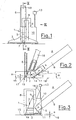
- Fig. 1
- den erfindungsgemäßen Unterwasserreiniger in einer ersten Ausführungsvariante in einer Vorderansicht,
- Fig. 2
- den Unterwasserreiniger in einem Schnitt gemäß der Figur II-II in Fig. 1,
- Fig. 3
- den Unterwasserreiniger in einer Seitenansicht gemäß dem Pfeil III in Fig. 1,
- Fig. 4
- den erfindungsgemäßen Unterwasserreiniger in einer zweiten Ausführungsvariante,
- Fig. 5
- den Unterwasserreiniger in einem Schnitt gemäß der Linie V-V in Fig. 4,
- Fig. 6
- den Unterwasserreiniger in einem Schnitt gemäß der Linie VI-VI in Fig. 4,
- Fig. 7
- den Unterwasserreiniger in einer dritten Ausführungsvariante in einer Draufsicht,
- Fig. 8
- diesen Unterwasserreiniger in einer Schrägansicht; und
- Fig. 9
- den Unterwasserreiniger in einer weiteren Schrägansicht.
- Fig. 1
- the underwater cleaner according to the invention in a first embodiment in a front view,
- Fig. 2
- the underwater cleaner in a section according to the figure II-II in Fig. 1,
- Fig. 3
- the underwater cleaner in a side view according to the arrow III in Fig. 1,
- Fig. 4
- the underwater cleaner according to the invention in a second embodiment,
- Fig. 5
- the underwater cleaner in a section along the line VV in Fig. 4,
- Fig. 6
- the underwater cleaner in a section along the line VI-VI in Fig. 4,
- Fig. 7
- the underwater cleaner in a third embodiment in a plan view,
- Fig. 8
- this underwater cleaner in an oblique view; and
- Fig. 9
- the underwater cleaner in another oblique view.
Funktionsgleiche Teile sind in den Ausführungsvarianten mit gleichen Bezugszeichen versehen.Functionally identical parts are provided in the embodiment variants with the same reference numerals.
Der Unterwasserreiniger 1 weist ein eine Saugdüse 2 ausbildendes Saugdüsengehäuse 3 auf, welches einen Saugraum 4 umfasst. Vom Saugraum 4 geht ein Austrittskanal 5 aus, an welchen einen Filtereinrichtung 6 angeschlossen ist.The
Der Unterwasserreiniger 1 arbeitet nach den Wasserstrahlpumpen-Prinzip. In den domartigen Saugraum 4 mündet im Bereich der Saugdüse 2 eine Wasserstrahldüse 7 ein, welche mit einer externen oder internen Druckquelle verbunden ist. Die Druckquelle ist im Ausführungsbeispiel eine in das Saugdüsengehäuse 3 integrierte Tauchpumpe 10 deren Druckstutzen 9 über eine Verbindungsleitung 8 mit der Wasserstrahldüse 7 strömungsverbunden ist. Die Ansaugöffnung 11 der Tauchpumpe 10 befindet sich in der in den Fig. 1 bis Fig. 3 dargestellten Ausführung dabei außerhalb des Saugdüsengehäuses 3 im Bodenbereich des Unterwasserreinigers 1 nahe der durch den Saugmund 19 definierten Saugebene 16, wobei im Bereich der Ansaugöffnung 11 ein Sieb 12 angeordnet ist, um grobe Verunreinigungen abzuhalten. Der Abstand zwischen der Ansaugöffnung 11 und der Saugebene 16 des Unterwasserreinigers 1 ist dabei wesentlich geringer als die maximale Hohe H des Saugraumes 4. Durch die tief angeordnete Ansaugöffnung 11 kann der Unterwasserreiniger 1 auch bei sehr geringen Wassertiefen eingesetzt werden.The
Über die durch eine Batterie oder einen Akkumulator 13 mit Gleichstrom versorgte Tauchpumpe 10 und die Wasserstrahldüse 7 wird in den Saugraum 4 ein scharfer Wasserstrahl zugeführt, welcher im Saugraum 4 einen Unterdruck erzeugt, wodurch über die Saugdüse 2 verunreinigtes Wasser angesaugt und schließlich in die Filtereinrichtung 6 befördert wird. Das Wasser passiert die Filtereinrichtung 6 und wird danach wieder in das Schwimmbad zurückgeführt.About the supplied by a battery or a
Wesentlich ist, dass die Wasserstrahldüse 7 möglichst nahe an der Saugebene 16 angeordnet ist. Für die Wirkung des Unterwasserreinigers 1 hat es sich als besonders vorteilhaft erwiesen, wenn der Abstand h zwischen der Mündung der Wasserstrahldüse 7 und der Saugebene 16 kleiner als die halbe innere Breite b des Austrittskanals 5 ist und beispielsweise weniger als 7 cm, vorzugsweise weniger als 3 cm beträgt. Dadurch wird erreicht, dass auch massereichere Verunreinigungen, wie beispielsweise kleinere und mittlere Kieselsteine 14 vom zu reinigenden Körper 15, beispielsweise vom Boden eines Schwimmbades entfernt werden können, da die Kieselsteine 14 vom Wasserstrahl weggerissen und in Richtung des Austrittskanals 5 gedrückt werden. Die Wirkung des Unterwasserreinigers 1 beruht somit auf einer Kombination zwischen Saug- und Druckwirkung zufolge des in den Saugraum 4 einströmenden Wasserstrahles, welcher durch den Pfeil S in Fig. 2 angedeutet ist. Die beste Saugwirkung wird erzielt, wenn im Betrieb die Saugebene 16 mit der Ebene des zu reinigenden Körpers 15 zusammenfällt.It is essential that the
Im Mündungsbereich in den Saugraum 4 sollte die Wasserstrahldüse 7 leicht nach oben in Richtung des Austrittskanals 5 geneigt sein, um einen besonders raschen Abtransport der Verunreinigungen in die Filtereinrichtung 6 zu ermöglichen. Wenn der Winkel α, der durch die Mittellinie 7' im Mündungsbereich der Wasserstrahldüse 7 in den Saugraum 4 einerseits und der mit dem zu reinigenden Körper 15 im Betrieb des Unterwasserreinigers 1 etwa parallel ausgebildeten Saugebene 16 im Bodenbereich des Saugdüsengehäuses 3 andererseits, aufgespannt wird, höchstens 45°, vorzugsweise höchstens 25°, besonders vorzugsweise maximal 15° beträgt, so dass der durch den Pfeil S in Fig. 2 angedeutete Wasserstrahl in Richtung des Austrittskanals 5 strömt, wird ein rascher Abtransport der Verunreinigungen in die Filtereinrichtung 6 ermöglicht.In the mouth region in the
Um die Saugwirkung der Saugdüse 2 zu erhöhen, ist die Saugdüse 2 von den Saugmund 19 bildenden Gummilippen oder Bürsten 17 umgeben. Dadurch lässt sich auch bei unebenem Körper 15 eine hervorragende Saugwirkung erzielen.In order to increase the suction effect of the
Über eine in einem starren Winkel am Saugdüsengehäuse 3 angebrachte, beispielsweise teleskopartig ausziehbare Betätigungsstange 18 kann der Unterwasserreiniger 1 über den Schwimmbadboden 15 geführt werden. Da die Filtereinrichtung 6 auf der dem Benutzer zugewandten Betätigungsseite A angeordnet ist, hat der Benutzer freie Sicht auf den in Fahrtrichtung des Unterwasserreinigers 1 liegenden noch zu reinigenden Körper 15 und kann somit abzusaugende Verunreinigungen rasch erkennen und den Unterwasserreiniger 1 auch beispielsweise in sonst schwer zugänglichen Ecken oder im Bereich von Stufen eines Schwimmbades einsetzen.The
Die Figuren 4 bis 6 zeigen eine zweite Ausführung, bei der die Ausgangsöffnung 11 der Tauchpumpe 10 höher als die der Druckstutzen 9 in einem seitlichen Bereich des Unterwasserreinigers 1 angeordnet ist. Die Tauchpumpe 10 ist dabei über Befestigungsklammern 20 am Saugdüsengehäuse 3 befestigt. Dies ermöglicht eine sehr kostengünstige Fertigung. Die von der Saugebene 16 entfernte Ausgangsöffnung 11 hat den Vorteil, dass relativ reines Wasser durch die Taupumpe 10 strömt und ein Verlegen des Siebes 12 kaum zu erwarten ist.Figures 4 to 6 show a second embodiment, in which the outlet opening 11 of the
Wie der Fig. 4 zu entnehmen ist, ist die Tauchpumpe 10 über ein als Spiralkanal ausgebildetes Kabel 21 mit dem Batteriegehäuse 13 verbunden. Das Batteriegehäuse 13 ist über nicht weiter dargestellte Gummibänder lösbar an der Betätigungsstange 18 befestigt. Die Steckverbindung 22 des Kabels 21 am Batteriegehäuse 13 ist gegen unbeabsichtigtes Lösen gesichert.As can be seen from FIG. 4, the
Die Fig. 7 bis Fig. 9 zeigen eine weitere Ausführung eines Unterwasserreinigers, wobei die Tauchpumpe 10 und das Batteriegehäuse 13 in das Saugdüsengehäuse 3 integriert ist. Mit Bezugszeichen 23 ist ein Anschluss für einen Ladestecker für den Akkumulator bezeichnet. Der elektrische Anaschluss 23 ist beispielsweise durch eine aufgeschraubte Abdeckkappe gegenüber dem umgebenden Wasser abgedichtet. Bezugszeichen 24 bezeichnet einen Dichtbereich, in welchem elektrische Teile wie Batteriegehäuse 13, Leitungen und elektrischer Anschluss 23 gegen Wasser abgedichtet sind.FIGS. 7 to 9 show a further embodiment of an underwater cleaner, wherein the
Das Einschalten des Unterwasserreinigers 1 kann über Schalter, Wassersensor oder Magnetschalter erfolgen.The
Gegebenenfalls kann der Unterwasserreiniger 1 noch eine spezielle Verkleidung, beispielsweise eine Tierform, aufweisen.Optionally, the
Das beim Unterwasserreiniger 1 angewandte kombinierte Saug- und Druckprinzip zum Lösen und Abtransportieren der Verunreinigungen ermöglicht es, die Tauchpumpe 10 sehr klein zu dimensionieren und den Unterwasserreiniger 1 sehr kompakt und leicht zu konzipieren.The combined suction and pressure principle applied to the
In einer alternativen Ausführung kann die Wasserstrahldüse 7 über die Verbindungsleitung 8 anstelle mit der Tauchpumpe 10 auch mit einer externen Wasserdruckquelle, beispielsweise einem an eine Wasserleitung angeschlossenen Schlauch, verbunden sein. Auf diese Weise kann auf eine Tauchpumpe 10 und eine Stromquelle verzichtet werden. Allerdings wird in dieser Ausführung zusätzlich Wasser in das Schwimmbad eingeleitet, was nicht immer erwünscht ist.In an alternative embodiment, the
Claims (17)
- An underwater cleaner (1), especially for a swimming pool, comprising a suction nozzle housing (3) with a suction nozzle (2) communicating with a suction chamber (4) and a suction orifice (19) defining a suction plane (16), with an outlet channel (5) originating from the suction chamber (4) to which a filter unit (6) is connected, and a water jet nozzle (7) opening into the suction chamber (4) through which water can be supplied under pressure into the suction chamber (4) in such a way that according to the principle of the water jet pump a negative pressure is produced in the suction chamber (4), with the water jet nozzle (7) opening into the suction chamber (4) in the region of the suction nozzle (2), and with the distance (h) between the water jet nozzle (7) and the suction plane (16) being smaller than the smallest inner width (b) of the outlet channel (5), characterized in that the water jet nozzle (7) faces away from the suction plane (16) and that the flow center line (7') of the water jet nozzle (7) encloses with the suction plane (16) an angle (α) > 0° and ≤ 45° in the region of the opening into the suction chamber (4).
- An underwater cleaner (1) according to claim 1, characterized in that the distance (h) between the water jet nozzle (7) and the suction plane (16) corresponds at most to 2/3 of the smallest inner width (b), preferably a maximum of half the smallest inner width (b) of the outlet channel (5).
- An underwater cleaner (1) according to claim 1 or 2, characterized in that the distance (h) between the water jet nozzle (7) and the suction plane (16) is smaller than half the maximum height (H) of the suction chamber (4).
- An underwater cleaner (1) according to one of the claims 1 to 3, characterized in that the distance (h) between the water jet nozzle (7) and the suction plane (16) is at most 7 cm, preferably at most 3 cm, and more preferably at most 2.5 cm.
- An underwater cleaner (1) according to one of the claims 1 to 4, characterized in that the angle (α) between the flow center line (7') of the water jet nozzle (7) and the suction plane (16) is preferably ≤ 25°, more preferably ≤ 15°.
- An underwater cleaner (1) according to one of the claims 1 to 5, characterized in that a hose connected to an external pressure source can be connected to the water jet nozzle (7).
- An underwater cleaner (1) according to one of the claims 1 to 5, comprising an integrated, preferably battery-operated submerged pump (10) whose pressure joints (9) are flow-connected via a connecting line (8) with the water jet nozzle (7), characterized in that the suction opening (11) of the submerged pump (10) is arranged outside of the suction chamber (4), preferably outside of the suction nozzle housing (3), and is hydraulically separated from the suction chamber (4).
- An underwater cleaner (1) according to claim 7, characterized in that the suction opening (11) is arranged in the region of the suction plane (16), with preferably the distance (a) between suction opening (11) and suction plane (16) being smaller than the maximum height (H), more preferably smaller than half the maximum height (h) of the suction chamber (4).
- An underwater cleaner (1) according to one of the claims 1 to 8, comprising an actuating rod (18) which is connected with the suction nozzle housing (3) and is inclined towards one actuating side (A), characterized in that the outlet channel (5) and the filter device (6) is arranged on the actuating side (A) of the suction nozzle housing (3) facing the user.
- An underwater cleaner (1) according to one of the claims 1 to 9, characterized in that the suction nozzle (2) is enclosed on its suction side facing the body (15) to be sucked off at least partly by rubber lips or brushes (17) forming the suction orifice (19).
- An underwater cleaner (1) according to one of the claims 1 to 10, characterized in that the suction nozzle (2) has an inner width (B) which is smaller than the width (b) of the outlet channel (5).
- An underwater cleaner (1) according to one of the claims 1 to 11, characterized in that the submerged pump (10) is connected with a battery housing (13) by way of a power cable preferably arranged as a spiral channel.
- An underwater cleaner (1) according to one of the claims 1 to 12, characterized in that the battery housing (13) is detachably fastened to an actuating rod (18) preferably with a rubber band.
- An underwater cleaner (1) according to one of the claims 1 to 13, characterized in that the axis (5') of the outlet channel (5) to the suction plane (16) is inclined by an angle (β) between 0° and 45°, preferably between 10° and 15°.
- An underwater cleaner (1) according to one of the claims 1 to 14, characterized in that the water jet nozzle (7) opens into the suction chamber (4) on a side opposite of the outlet channel (5).
- An underwater cleaner (1) according to one of the claims 1 to 15, characterized in that the water jet nozzle (7) is directed into the outlet channel (5), with the flow center line (7') enclosing with the axis (5') of the outlet channel (5) an angle (γ) smaller than 180°, preferably between 150° and 170°.
- An underwater cleaner (1) according to one of the claims 1 to 16, characterized in that the submerged pump (10) and/or the battery housing (13) are integrated in the suction nozzle housing (3).
Priority Applications (1)
| Application Number | Priority Date | Filing Date | Title |
|---|---|---|---|
| AT04737357T ATE340293T1 (en) | 2003-08-21 | 2004-06-29 | UNDERWATER CLEANER |
Applications Claiming Priority (3)
| Application Number | Priority Date | Filing Date | Title |
|---|---|---|---|
| AT5822003 | 2003-08-21 | ||
| AT5822003U | 2003-08-21 | ||
| PCT/AT2004/000226 WO2005021896A1 (en) | 2003-08-21 | 2004-06-29 | Underwater cleaner |
Publications (2)
| Publication Number | Publication Date |
|---|---|
| EP1530664A1 EP1530664A1 (en) | 2005-05-18 |
| EP1530664B1 true EP1530664B1 (en) | 2006-09-20 |
Family
ID=34229610
Family Applications (1)
| Application Number | Title | Priority Date | Filing Date |
|---|---|---|---|
| EP04737357A Expired - Lifetime EP1530664B1 (en) | 2003-08-21 | 2004-06-29 | Underwater cleaner |
Country Status (5)
| Country | Link |
|---|---|
| US (1) | US20060254004A1 (en) |
| EP (1) | EP1530664B1 (en) |
| AT (1) | ATE340293T1 (en) |
| DE (1) | DE502004001526D1 (en) |
| WO (1) | WO2005021896A1 (en) |
Families Citing this family (17)
| Publication number | Priority date | Publication date | Assignee | Title |
|---|---|---|---|---|
| US9593502B2 (en) | 2009-10-19 | 2017-03-14 | Hayward Industries, Inc. | Swimming pool cleaner |
| US8402585B2 (en) * | 2009-10-19 | 2013-03-26 | Poolvergnuegen | Convertible pressure/suction swimming pool cleaner |
| US20180255750A1 (en) * | 2017-01-06 | 2018-09-13 | Kristopher L. Anderson | Device and method for cleaning aquariums |
| US11634224B2 (en) * | 2019-06-03 | 2023-04-25 | Zodiac Pool Systems Llc | Aerial delivery of chemicals for swimming pools and spas |
| CN111168575A (en) * | 2020-02-12 | 2020-05-19 | 佛山市锐驰科技有限公司 | A five-axis waterjet cutter head for large-angle cutting underwater |
| US11881093B2 (en) | 2020-08-20 | 2024-01-23 | Denso International America, Inc. | Systems and methods for identifying smoking in vehicles |
| US11760169B2 (en) | 2020-08-20 | 2023-09-19 | Denso International America, Inc. | Particulate control systems and methods for olfaction sensors |
| US12017506B2 (en) | 2020-08-20 | 2024-06-25 | Denso International America, Inc. | Passenger cabin air control systems and methods |
| US11932080B2 (en) | 2020-08-20 | 2024-03-19 | Denso International America, Inc. | Diagnostic and recirculation control systems and methods |
| US12269315B2 (en) | 2020-08-20 | 2025-04-08 | Denso International America, Inc. | Systems and methods for measuring and managing odor brought into rental vehicles |
| US11636870B2 (en) | 2020-08-20 | 2023-04-25 | Denso International America, Inc. | Smoking cessation systems and methods |
| US12377711B2 (en) | 2020-08-20 | 2025-08-05 | Denso International America, Inc. | Vehicle feature control systems and methods based on smoking |
| US11760170B2 (en) | 2020-08-20 | 2023-09-19 | Denso International America, Inc. | Olfaction sensor preservation systems and methods |
| US12251991B2 (en) | 2020-08-20 | 2025-03-18 | Denso International America, Inc. | Humidity control for olfaction sensors |
| US11828210B2 (en) | 2020-08-20 | 2023-11-28 | Denso International America, Inc. | Diagnostic systems and methods of vehicles using olfaction |
| US11813926B2 (en) | 2020-08-20 | 2023-11-14 | Denso International America, Inc. | Binding agent and olfaction sensor |
| AT525345B1 (en) | 2021-11-17 | 2023-03-15 | Andres Fraenkel | UNDERWATER CLEANER |
Family Cites Families (22)
| Publication number | Priority date | Publication date | Assignee | Title |
|---|---|---|---|---|
| US453246A (en) | 1891-06-02 | nichols | ||
| DE950964C (en) * | 1951-09-21 | 1956-10-18 | Oscar Pauser | Underwater cleaning device for swimming pools |
| US2725356A (en) * | 1953-10-09 | 1955-11-29 | Oliver M Lombardi | Swimming pool cleaner device and method |
| US3287755A (en) * | 1965-02-15 | 1966-11-29 | Andrew L Pansini | Device for cleaning swimming pools |
| US3444575A (en) * | 1967-05-02 | 1969-05-20 | Louis A Dore Jr | Pool cleaner |
| US3961393A (en) * | 1974-10-21 | 1976-06-08 | Pansini Andrew L | Swimming pool cleaning apparatus |
| US3932281A (en) * | 1974-12-12 | 1976-01-13 | Pansini Andrew L | Leaf trap kit for swimming pools |
| NL171184C (en) * | 1977-11-07 | 1983-02-16 | Konijn Machinebouw Nv | DEVICE FOR CLEANING THE BOTTOM OF A BEACH, A RECREATION POND OR THE LIKE. |
| US4240173A (en) * | 1979-07-13 | 1980-12-23 | Sherrill John C | Pool vacuum |
| US4962559A (en) | 1988-11-16 | 1990-10-16 | Rainbow Lifegard Products, Inc. | Submersible vacuum cleaner |
| US4950393A (en) | 1989-03-29 | 1990-08-21 | Lewis D. Ghiz | Operatively stationary pool cleaning apparatus |
| FR2667099B1 (en) | 1990-09-21 | 1993-11-05 | Pierre Monetta | ADAPTABLE VACUUM CLEANER FOR POOL BRUSHES. |
| FR2683845B1 (en) * | 1991-11-20 | 1996-03-01 | Pierre Monetta | IMPROVEMENTS ON VACUUM CLEANERS ADAPTABLE FOR POOL BRUSHES. |
| US5317776A (en) * | 1993-03-22 | 1994-06-07 | Demoura Robert J | Swimming pool vacuum apparatus |
| US5336403A (en) * | 1993-10-25 | 1994-08-09 | Sevylor International, Sa | Submersible swimming pool cleaner |
| FR2715960B3 (en) * | 1994-02-08 | 1996-08-30 | Pierre Monetta | Reduced volume suction and filter broom for swimming pools. |
| US5450644A (en) * | 1994-03-14 | 1995-09-19 | Berman; Ken | Self-contained submersible debris cleaner |
| US5842243A (en) | 1997-04-24 | 1998-12-01 | Aqua Products Inc. | Manually propelled pool cleaner |
| CZ298657B6 (en) * | 1997-07-11 | 2007-12-12 | Moyra A. Phillipson Family Trust | Swimming pool cleaning device |
| EP0989255B1 (en) | 1998-09-23 | 2004-04-28 | 3S Systemtechnik Ag | Cleaning apparatus for swimming-pool |
| AU139884S (en) * | 1999-06-07 | 2000-02-22 | Pool Systems Pty Ltd | A pool vaccum head |
| US6502269B1 (en) | 1999-10-14 | 2003-01-07 | John A. Balchan | Electric powered portable pool cleaner |
-
2004
- 2004-06-29 AT AT04737357T patent/ATE340293T1/en not_active IP Right Cessation
- 2004-06-29 DE DE502004001526T patent/DE502004001526D1/en not_active Expired - Fee Related
- 2004-06-29 EP EP04737357A patent/EP1530664B1/en not_active Expired - Lifetime
- 2004-06-29 WO PCT/AT2004/000226 patent/WO2005021896A1/en not_active Ceased
- 2004-06-29 US US10/568,778 patent/US20060254004A1/en not_active Abandoned
Also Published As
| Publication number | Publication date |
|---|---|
| DE502004001526D1 (en) | 2006-11-02 |
| US20060254004A1 (en) | 2006-11-16 |
| EP1530664A1 (en) | 2005-05-18 |
| ATE340293T1 (en) | 2006-10-15 |
| WO2005021896A1 (en) | 2005-03-10 |
Similar Documents
| Publication | Publication Date | Title |
|---|---|---|
| EP1530664B1 (en) | Underwater cleaner | |
| EP0155502B1 (en) | Cleaning apparatus for swimming-pools or the like | |
| DE69826217T2 (en) | FILTER BAG FOR A SWIMMING POOL CLEANER | |
| DE69701127T2 (en) | DEVICE FOR CLEANING FLOORS, CARPETS AND THE LIKE | |
| DE10014834C2 (en) | Blow and suction gun | |
| EP3073882A1 (en) | Cyclonic separator device | |
| DE19505306A1 (en) | Filtration system having tightly closed housing contg. filter material | |
| DE602004002593T2 (en) | WATER CIRCULATION UNIT WITH INCREASED PUMP AND THIS FILTER UNIT | |
| EP1506805A1 (en) | Air cleaning device | |
| DE4106088A1 (en) | Flushing and emptying tank - involves port with filter connecting main part to fresh-water tank with pump | |
| DE102023108163A1 (en) | UNDERWATER CLEANER | |
| DE10250389B4 (en) | Steam jet device of a vacuum cleaner | |
| DE10239243B4 (en) | High pressure cleaner with water recycling | |
| AT525345B1 (en) | UNDERWATER CLEANER | |
| DE10257241B4 (en) | Device, in particular workshop and / or Hobbysystem for processing, in particular vacuum suction of surfaces | |
| AT413569B (en) | UNDERWATER CLEANER | |
| DE20121272U1 (en) | Device, in particular workshop and / or hobby system for processing, in particular vacuum suction, of surfaces | |
| DE19530976A1 (en) | Vacuum cleaner | |
| DE3436064A1 (en) | Wet and dry vacuum cleaner | |
| DE69007306T2 (en) | Micro sandblasting machine and device for cleaning exhaust air from a micro sandblasting chamber. | |
| EP2777465B1 (en) | Floor cleaning machine with handheld suction hose | |
| DE3923460C2 (en) | ||
| DE3433571A1 (en) | Vacuum cess pool cleaner vehicle | |
| AT19134B (en) | Device for removing dust deposits in carpets and the like like | |
| DE10202933A1 (en) | Moisture suction unit for cleaning surfaces has integrated suction pump and a reversibly separable two part housing with sealed sections |
Legal Events
| Date | Code | Title | Description |
|---|---|---|---|
| PUAI | Public reference made under article 153(3) epc to a published international application that has entered the european phase |
Free format text: ORIGINAL CODE: 0009012 |
|
| 17P | Request for examination filed |
Effective date: 20050218 |
|
| AK | Designated contracting states |
Kind code of ref document: A1 Designated state(s): AT BE BG CH CY CZ DE DK EE ES FI FR GB GR HU IE IT LI LU MC NL PL PT RO SE SI SK TR |
|
| AX | Request for extension of the european patent |
Extension state: AL HR LT LV MK |
|
| GRAP | Despatch of communication of intention to grant a patent |
Free format text: ORIGINAL CODE: EPIDOSNIGR1 |
|
| GRAS | Grant fee paid |
Free format text: ORIGINAL CODE: EPIDOSNIGR3 |
|
| GRAA | (expected) grant |
Free format text: ORIGINAL CODE: 0009210 |
|
| AK | Designated contracting states |
Kind code of ref document: B1 Designated state(s): AT BE BG CH CY CZ DE DK EE ES FI FR GB GR HU IE IT LI LU MC NL PL PT RO SE SI SK TR |
|
| DAX | Request for extension of the european patent (deleted) | ||
| PG25 | Lapsed in a contracting state [announced via postgrant information from national office to epo] |
Ref country code: IT Free format text: LAPSE BECAUSE OF FAILURE TO SUBMIT A TRANSLATION OF THE DESCRIPTION OR TO PAY THE FEE WITHIN THE PRESCRIBED TIME-LIMIT;WARNING: LAPSES OF ITALIAN PATENTS WITH EFFECTIVE DATE BEFORE 2007 MAY HAVE OCCURRED AT ANY TIME BEFORE 2007. THE CORRECT EFFECTIVE DATE MAY BE DIFFERENT FROM THE ONE RECORDED. Effective date: 20060920 Ref country code: NL Free format text: LAPSE BECAUSE OF FAILURE TO SUBMIT A TRANSLATION OF THE DESCRIPTION OR TO PAY THE FEE WITHIN THE PRESCRIBED TIME-LIMIT Effective date: 20060920 Ref country code: RO Free format text: LAPSE BECAUSE OF FAILURE TO SUBMIT A TRANSLATION OF THE DESCRIPTION OR TO PAY THE FEE WITHIN THE PRESCRIBED TIME-LIMIT Effective date: 20060920 Ref country code: SI Free format text: LAPSE BECAUSE OF FAILURE TO SUBMIT A TRANSLATION OF THE DESCRIPTION OR TO PAY THE FEE WITHIN THE PRESCRIBED TIME-LIMIT Effective date: 20060920 Ref country code: IE Free format text: LAPSE BECAUSE OF FAILURE TO SUBMIT A TRANSLATION OF THE DESCRIPTION OR TO PAY THE FEE WITHIN THE PRESCRIBED TIME-LIMIT Effective date: 20060920 Ref country code: CZ Free format text: LAPSE BECAUSE OF FAILURE TO SUBMIT A TRANSLATION OF THE DESCRIPTION OR TO PAY THE FEE WITHIN THE PRESCRIBED TIME-LIMIT Effective date: 20060920 Ref country code: PL Free format text: LAPSE BECAUSE OF FAILURE TO SUBMIT A TRANSLATION OF THE DESCRIPTION OR TO PAY THE FEE WITHIN THE PRESCRIBED TIME-LIMIT Effective date: 20060920 Ref country code: FI Free format text: LAPSE BECAUSE OF FAILURE TO SUBMIT A TRANSLATION OF THE DESCRIPTION OR TO PAY THE FEE WITHIN THE PRESCRIBED TIME-LIMIT Effective date: 20060920 Ref country code: GB Free format text: LAPSE BECAUSE OF FAILURE TO SUBMIT A TRANSLATION OF THE DESCRIPTION OR TO PAY THE FEE WITHIN THE PRESCRIBED TIME-LIMIT Effective date: 20060920 Ref country code: SK Free format text: LAPSE BECAUSE OF FAILURE TO SUBMIT A TRANSLATION OF THE DESCRIPTION OR TO PAY THE FEE WITHIN THE PRESCRIBED TIME-LIMIT Effective date: 20060920 |
|
| REG | Reference to a national code |
Ref country code: GB Ref legal event code: FG4D Free format text: NOT ENGLISH |
|
| REG | Reference to a national code |
Ref country code: CH Ref legal event code: EP |
|
| REG | Reference to a national code |
Ref country code: IE Ref legal event code: FG4D Free format text: LANGUAGE OF EP DOCUMENT: GERMAN |
|
| REF | Corresponds to: |
Ref document number: 502004001526 Country of ref document: DE Date of ref document: 20061102 Kind code of ref document: P |
|
| PG25 | Lapsed in a contracting state [announced via postgrant information from national office to epo] |
Ref country code: BG Free format text: LAPSE BECAUSE OF FAILURE TO SUBMIT A TRANSLATION OF THE DESCRIPTION OR TO PAY THE FEE WITHIN THE PRESCRIBED TIME-LIMIT Effective date: 20061220 Ref country code: DK Free format text: LAPSE BECAUSE OF FAILURE TO SUBMIT A TRANSLATION OF THE DESCRIPTION OR TO PAY THE FEE WITHIN THE PRESCRIBED TIME-LIMIT Effective date: 20061220 Ref country code: SE Free format text: LAPSE BECAUSE OF FAILURE TO SUBMIT A TRANSLATION OF THE DESCRIPTION OR TO PAY THE FEE WITHIN THE PRESCRIBED TIME-LIMIT Effective date: 20061220 |
|
| RAP2 | Party data changed (patent owner data changed or rights of a patent transferred) |
Owner name: BATTERY POOL CLEANER GMBH NFG. KEG |
|
| PG25 | Lapsed in a contracting state [announced via postgrant information from national office to epo] |
Ref country code: ES Free format text: LAPSE BECAUSE OF FAILURE TO SUBMIT A TRANSLATION OF THE DESCRIPTION OR TO PAY THE FEE WITHIN THE PRESCRIBED TIME-LIMIT Effective date: 20061231 |
|
| NLT2 | Nl: modifications (of names), taken from the european patent patent bulletin |
Owner name: BATTERY POOL CLEANER GMBH NFG. KEG Effective date: 20061227 |
|
| NLV1 | Nl: lapsed or annulled due to failure to fulfill the requirements of art. 29p and 29m of the patents act | ||
| PG25 | Lapsed in a contracting state [announced via postgrant information from national office to epo] |
Ref country code: PT Free format text: LAPSE BECAUSE OF FAILURE TO SUBMIT A TRANSLATION OF THE DESCRIPTION OR TO PAY THE FEE WITHIN THE PRESCRIBED TIME-LIMIT Effective date: 20070312 |
|
| REG | Reference to a national code |
Ref country code: IE Ref legal event code: FD4D |
|
| ET | Fr: translation filed | ||
| PLBE | No opposition filed within time limit |
Free format text: ORIGINAL CODE: 0009261 |
|
| STAA | Information on the status of an ep patent application or granted ep patent |
Free format text: STATUS: NO OPPOSITION FILED WITHIN TIME LIMIT |
|
| 26N | No opposition filed |
Effective date: 20070621 |
|
| BERE | Be: lapsed |
Owner name: BATTERY POOL CLEANER GMBH Effective date: 20070630 |
|
| PG25 | Lapsed in a contracting state [announced via postgrant information from national office to epo] |
Ref country code: MC Free format text: LAPSE BECAUSE OF NON-PAYMENT OF DUE FEES Effective date: 20070630 |
|
| PG25 | Lapsed in a contracting state [announced via postgrant information from national office to epo] |
Ref country code: BE Free format text: LAPSE BECAUSE OF NON-PAYMENT OF DUE FEES Effective date: 20070630 |
|
| PG25 | Lapsed in a contracting state [announced via postgrant information from national office to epo] |
Ref country code: GR Free format text: LAPSE BECAUSE OF FAILURE TO SUBMIT A TRANSLATION OF THE DESCRIPTION OR TO PAY THE FEE WITHIN THE PRESCRIBED TIME-LIMIT Effective date: 20061221 |
|
| PG25 | Lapsed in a contracting state [announced via postgrant information from national office to epo] |
Ref country code: EE Free format text: LAPSE BECAUSE OF FAILURE TO SUBMIT A TRANSLATION OF THE DESCRIPTION OR TO PAY THE FEE WITHIN THE PRESCRIBED TIME-LIMIT Effective date: 20060920 |
|
| PG25 | Lapsed in a contracting state [announced via postgrant information from national office to epo] |
Ref country code: AT Free format text: LAPSE BECAUSE OF NON-PAYMENT OF DUE FEES Effective date: 20070629 |
|
| PGFP | Annual fee paid to national office [announced via postgrant information from national office to epo] |
Ref country code: DE Payment date: 20080612 Year of fee payment: 5 |
|
| PGFP | Annual fee paid to national office [announced via postgrant information from national office to epo] |
Ref country code: FR Payment date: 20080626 Year of fee payment: 5 |
|
| REG | Reference to a national code |
Ref country code: CH Ref legal event code: PL |
|
| PG25 | Lapsed in a contracting state [announced via postgrant information from national office to epo] |
Ref country code: CH Free format text: LAPSE BECAUSE OF NON-PAYMENT OF DUE FEES Effective date: 20080630 Ref country code: LI Free format text: LAPSE BECAUSE OF NON-PAYMENT OF DUE FEES Effective date: 20080630 |
|
| PG25 | Lapsed in a contracting state [announced via postgrant information from national office to epo] |
Ref country code: LU Free format text: LAPSE BECAUSE OF NON-PAYMENT OF DUE FEES Effective date: 20070629 Ref country code: CY Free format text: LAPSE BECAUSE OF FAILURE TO SUBMIT A TRANSLATION OF THE DESCRIPTION OR TO PAY THE FEE WITHIN THE PRESCRIBED TIME-LIMIT Effective date: 20060920 |
|
| PG25 | Lapsed in a contracting state [announced via postgrant information from national office to epo] |
Ref country code: TR Free format text: LAPSE BECAUSE OF FAILURE TO SUBMIT A TRANSLATION OF THE DESCRIPTION OR TO PAY THE FEE WITHIN THE PRESCRIBED TIME-LIMIT Effective date: 20060920 Ref country code: HU Free format text: LAPSE BECAUSE OF FAILURE TO SUBMIT A TRANSLATION OF THE DESCRIPTION OR TO PAY THE FEE WITHIN THE PRESCRIBED TIME-LIMIT Effective date: 20070321 |
|
| REG | Reference to a national code |
Ref country code: FR Ref legal event code: ST Effective date: 20100226 |
|
| PG25 | Lapsed in a contracting state [announced via postgrant information from national office to epo] |
Ref country code: FR Free format text: LAPSE BECAUSE OF NON-PAYMENT OF DUE FEES Effective date: 20090630 |
|
| PG25 | Lapsed in a contracting state [announced via postgrant information from national office to epo] |
Ref country code: DE Free format text: LAPSE BECAUSE OF NON-PAYMENT OF DUE FEES Effective date: 20100101 |