EP1530268A1 - Gehäuse für einen elektrischen Steckverbinder - Google Patents
Gehäuse für einen elektrischen Steckverbinder Download PDFInfo
- Publication number
- EP1530268A1 EP1530268A1 EP04003063A EP04003063A EP1530268A1 EP 1530268 A1 EP1530268 A1 EP 1530268A1 EP 04003063 A EP04003063 A EP 04003063A EP 04003063 A EP04003063 A EP 04003063A EP 1530268 A1 EP1530268 A1 EP 1530268A1
- Authority
- EP
- European Patent Office
- Prior art keywords
- housing
- latching
- housing according
- groove
- adapter
- Prior art date
- Legal status (The legal status is an assumption and is not a legal conclusion. Google has not performed a legal analysis and makes no representation as to the accuracy of the status listed.)
- Granted
Links
- 230000000295 complement effect Effects 0.000 claims abstract description 33
- 238000005192 partition Methods 0.000 claims description 4
- 239000002184 metal Substances 0.000 claims description 3
- 239000000463 material Substances 0.000 description 3
- 208000010543 22q11.2 deletion syndrome Diseases 0.000 description 1
- 150000001875 compounds Chemical class 0.000 description 1
Images

Classifications
-
- H—ELECTRICITY
- H01—ELECTRIC ELEMENTS
- H01R—ELECTRICALLY-CONDUCTIVE CONNECTIONS; STRUCTURAL ASSOCIATIONS OF A PLURALITY OF MUTUALLY-INSULATED ELECTRICAL CONNECTING ELEMENTS; COUPLING DEVICES; CURRENT COLLECTORS
- H01R13/00—Details of coupling devices of the kinds covered by groups H01R12/70 or H01R24/00 - H01R33/00
- H01R13/73—Means for mounting coupling parts to apparatus or structures, e.g. to a wall
-
- H—ELECTRICITY
- H01—ELECTRIC ELEMENTS
- H01R—ELECTRICALLY-CONDUCTIVE CONNECTIONS; STRUCTURAL ASSOCIATIONS OF A PLURALITY OF MUTUALLY-INSULATED ELECTRICAL CONNECTING ELEMENTS; COUPLING DEVICES; CURRENT COLLECTORS
- H01R13/00—Details of coupling devices of the kinds covered by groups H01R12/70 or H01R24/00 - H01R33/00
- H01R13/62—Means for facilitating engagement or disengagement of coupling parts or for holding them in engagement
- H01R13/627—Snap or like fastening
- H01R13/6271—Latching means integral with the housing
- H01R13/6272—Latching means integral with the housing comprising a single latching arm
Definitions
- the invention relates to a housing for an electrical connector, that with the housing of a complementary electrical connector, Adapters or the like can be latched, with one in Steckoder Axially extending groove into which a housing portion of the complementary connector or adapter is inserted, and with a latching arm for latching with the inserted housing section is provided with a latch. It also relates to an electrical Connector with such a housing.
- Electrical connectors are usually each with a complementary one Connectable connectors and serve the electrical and optionally also mechanical connection of electrical equipment such as. Cables and / or electrical appliances. They will in particular also used in motor vehicles.
- Connector housing of the type mentioned are well known.
- a housing is in particular with a Housing of a complementary electrical connector locked.
- This is in an outer housing wall in a plug or axial direction extending groove provided in which a latching arm is arranged.
- Locking arm is provided with a latching nose and resilient at one end pivoted.
- such a housing is on the opposite side Outer wall also with a complementary locking means provided, which is for example a locking shoulder or a Rastö réelle can act.
- a complementary locking means for the preparation of the compound in question between two housings is a complementary locking means in the sliding fit received in the groove, and the detent latched with the detent opening or shoulder. After the locking connection of the locking arm takes at least essentially his normal position again, in which he none is exposed to mechanical stress.
- this mounting plate can be provided with an opening into which the latching lug of the latching arm snaps. If the mounting plate is inserted into the groove, So she even exerts a force on the catch even if already a catch has occurred. This leaves the latching arm after latching the mounting plate clamped.
- the invention is based on the object, an improved housing as well to provide an improved connector of the type mentioned, where the aforementioned problem is eliminated.
- the axial groove for receiving both the housing portion of the complementary connector or adapter as well as a mounting plate recessed and the Latch arm between a the housing portion of the complementary Connector or adapter receiving outer groove portion and arranged a mounting plate receiving inner groove portion is, wherein the latching arm for latching with the in the outer groove portion accommodated housing portion of the complementary connector or adapters with a lying in the outer groove portion outer Latch and latched with the recorded in the inner groove portion Mounting plate with a lying in the inner groove portion is provided inside latch.
- the latching arm takes a latching with the mounting plate at least substantially back to its normal position one in which he is tension-free. Overall, this results in a more flexible Fixing the connectors even in non-accessible areas. After plugging in, no further steps are required. After this for latching with the housing of a respective complementary one electrical connector or adapter and for locking the mounting plate a common locking arm is provided, also results a material and cost saving. Finally, it will be a simple one Handling achieved. An attachment of the connectors on the mounting plate or a plastic, for example, counterpart is possible with the same locking arm.
- the latching arm is viewed in the depth direction of the groove at least essentially arranged centrally.
- the two groove sections can So have an at least substantially the same depth.
- the two groove sections may have a different width or at least substantially the same width.
- Housing is the outer groove portion as a standard recording for a respective housing section different complementary Connector or adapter executed.
- the axial groove is preferably provided in an outer housing wall or trained.
- the latching arm can be mounted at one end resiliently pivotable and / or be at least partially flexible or consist of flexible material.
- the housing On its side facing away from the locking arm, the housing is expediently provided with a complementary locking means.
- this complementary latching means may be, for example, a latching shoulder or opening act. This can then in particular with a Latch of a latching arm of a complementary connector or Interacting adapters.
- the mounting plate may be, for example, a sheet metal tab or the like.
- the housing can be used as a housing of a male part or as a housing Receiving part of the relevant connector system be executed.
- the electrical connector according to the invention is characterized from that it is provided with a housing according to the invention.
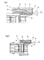
- Figures 1 to 3 show a schematic representation of an electrical Connector 10 of an electrical connector system. at the reproduced electrical connector 10 is in the present case, for example, a plug-in part of the connector system.
- FIG. 1 to 3 comprises the electrical Connector 10, a housing 12, which is connected to the housing of a complementary electrical connector, adapters or the like latched is.
- the housing 12 is extending in a plug-in or axial direction S.
- Groove 14 provided in the detail below Way in an outer groove portion 14 'and an inner groove portion 14 "is divided (see in particular Figure 3) outer, upper groove portion 14 'of the groove 14 a housing portion of a complementary connector or adapter insertable.
- the housing 12 also includes a latching arm 16 which is for latching with the inserted housing portion of the complementary connector or adapters with an outer, upper detent 18 provided is.
- the axial groove 14 is for receiving both the housing portion of the complementary connector or adapter as well as a mounting plate 20 or the like (see Figures 1 and 2) deepened.
- the locking arm 16 is between the housing portion of the complementary connector or Adapter receiving outer groove portion 14 'and the mounting plate 20 receiving inner groove portion 14 "arranged.
- the in the outer groove portion 14 'lying outer locking lug 18 of the latching arm 16 is used for locking with the recorded in the outer groove portion 14 ' Housing portion of the complementary connector or adapters.
- the locking arm 16 also with an im inner groove portion 14 "lying inner lower catch 22 provided.
- the locking arm 16 in Depth direction of the groove 14 considered at least substantially centrally be arranged.
- the two groove sections 14 ', 14 " can therefore at least have substantially the same depth (see in particular FIG 3).
- the two groove sections have 14 ', 14 "in the present case have a different width outer, upper groove portion 14 'is so here, for example, narrower than the inner, lower groove portion 14 ".
- the outer groove portion 14 ' may in particular as a standard recording for a housing portion of different complementary connector or adapter to be executed.
- the inner, lower serves Groove portion 14 ", for example, for receiving a mounting plate 20 at which is for example a sheet metal tab or the like can.
- the axial groove 14 can in particular on an outer housing wall be provided or trained.
- the latching arm 16 can at its left in Figures 1 and 2 end be mounted resiliently pivotable. He can be at least partially flexible Material exist.
- the housing 12th On its side remote from the locking arm 16 side, the housing 12th be provided for example with a complementary locking means.
- Locking arm 16 After a lock with the housing section of the complementary Connector or adapter and / or the mounting plate 20 can the Locking arm 16 again assume its de-energized normal position.
- a fixed partition 24 may be provided.
Landscapes
- Details Of Connecting Devices For Male And Female Coupling (AREA)
- Connector Housings Or Holding Contact Members (AREA)
- Coupling Device And Connection With Printed Circuit (AREA)
- Motor Or Generator Frames (AREA)
Abstract
Description
- Figur 1
- eine schematische geschnittene Teildarstellung eines elektrischen Steckverbinders, wobei es sich im vorliegenden Fall um das Steckteil des betreffenden Steckverbinder-Systems handelt,
- Figur 2
- eine schematische, teilweise geschnittene Seitenansicht des elektrischen Steckverbinders gemäß Figur 1,
- Figur 3
- eine schematische Stirnansicht des elektrischen Verbinders gemäß Figur 1, und
- Figuren 4 und 5
- verschiedene Einsatzmöglichen der jeweils eine Aufnahme bildenden Nutabschnitte.
- 10
- elektrischer Steckverbinder
- 12
- Gehäuse
- 14
- Nut
- 14'
- äußerer, oberer Nutabschnitt
- 14"
- innerer, unterer Nutabschnitt
- 16
- Rastarm
- 18
- äußere, obere Rastnase
- 20
- Montageplatte
- 22
- innere, untere Rastnase
- 24
- feststehende Trennwand
- S
- Steck- oder Axialrichtung
Claims (17)
- Gehäuse (12) für einen elektrischen Steckverbinder (10), das mit dem Gehäuse eines komplementären elektrischen Steckverbinders, Adapters oder dergleichen verrastbar ist, mit einer sich in Steckoder Axialrichtung (S) erstreckenden Nut (14), in die ein Gehäuseabschnitt des komplementären Steckverbinders bzw. Adapters einführbar ist, und mit einem Rastarm (16), der zur Verrastung mit dem eingeführten Gehäuseabschnitt mit einer Rastnase (18) versehen ist,
dadurch gekennzeichnet, dass die axiale Nut (14) zur Aufnahme sowohl des Gehäuseabschnitts des komplementären Steckverbinders bzw. Adapters als auch einer Montageplatte (20) vertieft und der Rastarm (16) zwischen einem den Gehäuseabschnitt des komplementären Steckverbinders bzw. Adapters aufnehmenden äußeren Nutabschnitt (14') und einem die Montageplatte aufnehmenden inneren Nutabschnitt (14") angeordnet ist, wobei der Rastarm (16) zur Verrastung mit dem im äußeren Nutabschnitt (14') aufgenommenen Gehäuseabschnitt des komplementären Steckverbinders bzw. Adapters mit einer im äußeren Nutabschnitt (14') liegenden äußeren Rastnase (18) und zur Verrastung mit der im inneren Nutabschnitt (14") aufgenommenen Montageplatte (20) mit einer im inneren Nutabschnitt (14") liegenden inneren Rastnase (22) versehen ist. - Gehäuse nach Anspruch 1,
dadurch gekennzeichnet, dass der Rastarm (16) in Tiefenrichtung der Nut (14) betrachtet zumindest im Wesentlichen zentral angeordnet ist. - Gehäuse nach Anspruch 2,
dadurch gekennzeichnet, dass die beiden Nutabschnitte (14', 14") zumindest im Wesentlichen eine gleiche Tiefe besitzen. - Gehäuse nach Anspruch 1,
dadurch gekennzeichnet, dass die beiden Nutabschnitte (14', 14") eine unterschiedliche Tiefe besitzen. - Gehäuse nach einem der vorhergehenden Ansprüche,
dadurch gekennzeichnet, dass die beiden Nutabschnitte (14', 14") eine unterschiedliche Breite besitzen. - Gehäuse nach einem der Ansprüche 1 bis 4,
dadurch gekennzeichnet, dass die beiden Nutabschnitte (14', 14") zumindest im Wesentlichen gleich breit sind. - Gehäuse nach einem der vorhergehenden Ansprüche,
dadurch gekennzeichnet, dass der äußere Nutabschnitt (14') als Standardaufnahme für einen Gehäuseabschnitt unterschiedlicher komplementärer Steckverbinder bzw. Adapter ausgeführt ist. - Gehäuse nach einem der vorhergehenden Ansprüche,
dadurch gekennzeichnet, dass die axiale Nut (14) in einer äußeren Gehäusewand vorgesehen bzw. ausgebildet ist. - Gehäuse nach einem der vorhergehenden Ansprüche,
dadurch gekennzeichnet, dass der Rastarm (16) an einem Ende federnd schwenkbar gelagert ist. - Gehäuse nach einem der vorhergehenden Ansprüche,
dadurch gekennzeichnet, dass der Rastarm (16) zumindest teilweise flexibel ist. - Gehäuse nach einem der vorhergehenden Ansprüche,
dadurch gekennzeichnet, dass es auf seiner vom Rastarm (16) abgewandten Seite mit einem komplementären Rastmittel versehen ist. - Gehäuse nach einem der vorhergehenden Ansprüche,
dadurch gekennzeichnet, dass der mit der Montageplatte (20) und/oder dem Gehäuseabschnitt des komplementären Steckverbinders bzw. Adapters verrastete Rastarm (16) wieder seine spannungslose Normalstellung einnimmt. - Gehäuse nach einem der vorhergehenden Ansprüche,
dadurch gekennzeichnet, dass die Montageplatte (20) eine Blechlasche oder dergleichen umfasst. - Gehäuse nach einem der vorhergehenden Ansprüche,
dadurch gekennzeichnet, dass zwischen den beiden Nutabschnitten bereichsweise eine feststehende Trennwand (24) vorgesehen ist. - Gehäuse nach einem der vorhergehenden Ansprüche,
dadurch gekennzeichnet, dass es als Gehäuse (12) eines Steckteils des betreffenden Steckverbinder-Systems ausgeführt ist. - Gehäuse nach einem der Ansprüche 1 bis 14,
dadurch gekennzeichnet, dass es als Gehäuse (12) eines Aufnahmeteils des betreffenden Steckverbinder-Systems ausgeführt ist. - Elektrischer Steckverbinder mit einem Gehäuse nach einem der vorhergehenden Ansprüche.
Applications Claiming Priority (2)
| Application Number | Priority Date | Filing Date | Title |
|---|---|---|---|
| GBGB0325805.0A GB0325805D0 (en) | 2003-11-05 | 2003-11-05 | Electrical connector housing |
| GB0325805 | 2003-11-05 |
Publications (2)
| Publication Number | Publication Date |
|---|---|
| EP1530268A1 true EP1530268A1 (de) | 2005-05-11 |
| EP1530268B1 EP1530268B1 (de) | 2006-08-23 |
Family
ID=29725978
Family Applications (1)
| Application Number | Title | Priority Date | Filing Date |
|---|---|---|---|
| EP04003063A Expired - Lifetime EP1530268B1 (de) | 2003-11-05 | 2004-02-11 | Gehäuse für einen elektrischen Steckverbinder |
Country Status (4)
| Country | Link |
|---|---|
| EP (1) | EP1530268B1 (de) |
| AT (1) | ATE337632T1 (de) |
| DE (1) | DE502004001257D1 (de) |
| GB (1) | GB0325805D0 (de) |
Citations (3)
| Publication number | Priority date | Publication date | Assignee | Title |
|---|---|---|---|---|
| EP0321169A2 (de) * | 1987-12-15 | 1989-06-21 | Honda Giken Kogyo Kabushiki Kaisha | Elektrischer Verbinder, der die Verhinderung unvollständiger Kupplung ermöglicht |
| US5048161A (en) * | 1989-05-25 | 1991-09-17 | Yazaki Corporation | Connector with lock onto panel |
| US5120240A (en) * | 1991-09-03 | 1992-06-09 | General Motors Corporation | Electrical connector with improved connector position assurance device |
-
2003
- 2003-11-05 GB GBGB0325805.0A patent/GB0325805D0/en not_active Ceased
-
2004
- 2004-02-11 AT AT04003063T patent/ATE337632T1/de not_active IP Right Cessation
- 2004-02-11 DE DE502004001257T patent/DE502004001257D1/de not_active Expired - Lifetime
- 2004-02-11 EP EP04003063A patent/EP1530268B1/de not_active Expired - Lifetime
Patent Citations (3)
| Publication number | Priority date | Publication date | Assignee | Title |
|---|---|---|---|---|
| EP0321169A2 (de) * | 1987-12-15 | 1989-06-21 | Honda Giken Kogyo Kabushiki Kaisha | Elektrischer Verbinder, der die Verhinderung unvollständiger Kupplung ermöglicht |
| US5048161A (en) * | 1989-05-25 | 1991-09-17 | Yazaki Corporation | Connector with lock onto panel |
| US5120240A (en) * | 1991-09-03 | 1992-06-09 | General Motors Corporation | Electrical connector with improved connector position assurance device |
Also Published As
| Publication number | Publication date |
|---|---|
| EP1530268B1 (de) | 2006-08-23 |
| DE502004001257D1 (de) | 2006-10-05 |
| ATE337632T1 (de) | 2006-09-15 |
| GB0325805D0 (en) | 2003-12-10 |
Similar Documents
| Publication | Publication Date | Title |
|---|---|---|
| DE69700207T2 (de) | Modularer elekrischer Verbinder | |
| EP1566674A1 (de) | Industrie-Steckergehäuse eines optischen Steckverbinders | |
| DE4222452A1 (de) | Abgeschirmter verbinder | |
| DE8613431U1 (de) | Verbinder mit einer Dichtung | |
| EP2332218B1 (de) | Netzstecker | |
| DE202012010451U1 (de) | Steckverbinder mit Isolierteil | |
| DE102004031825B4 (de) | Sammelschienensystem mit Montageeinheit aus Grundplatte und Befestigungsteilen | |
| DE102007045400B4 (de) | Netzstecker | |
| EP0444478A1 (de) | Kontaktträger für eine Steckdose oder einen Stecker für eine Steckverbindungen fÀ¼r den elektrischen Anschluss von Kraftfahrzeuganhängern | |
| DE69900798T2 (de) | Kupplung mit selbsttätiger Verbindung und Trennung | |
| DE60038472T2 (de) | Steckverbinder mit Kabelzugentlastung | |
| DE202009010037U1 (de) | Steckerverbindung aus zusammensteckbaren Steckverbindern | |
| EP3010092A1 (de) | Steckerelement, gegensteckerelement und elektrischer steckverbinder | |
| DE19950189B4 (de) | Stellantrieb, insbesondere zum Antrieb eines Kfz-Rückblickspiegels | |
| DE102016217456B3 (de) | Anordnung für einen elektrischen Steckverbinder sowie Steckverbinder mit einem Kontaktgehäuse, Umgehäuse und Sicherungselement | |
| DE20221894U1 (de) | Elektrischer Steckverbinder | |
| WO2025119422A1 (de) | Steckverbindermodul für einen modularen industriesteckverbinder | |
| DE4104370C2 (de) | Elektrischer Steckverbinder, insbesondere für Sensoren | |
| EP1530268B1 (de) | Gehäuse für einen elektrischen Steckverbinder | |
| EP1811609B1 (de) | Elektrischer Verbinder, elektrisches Verbindungssystem und Verfahren zur Bildung eines elektrischen Verbindungssystems | |
| DE29921719U1 (de) | Elektrische Steckverbinderkupplung | |
| DE20019792U1 (de) | Steckverbinder-Gehäuse mit Kodiereinrichtung | |
| DE19525801A1 (de) | Vorrichtung zum elektrisch leitenden Verbinden von zwei elektrischen Leitungen | |
| DE202005017981U1 (de) | Kontakthalterung für elektrische Steckverbinder | |
| DE102005030264A1 (de) | Geschlossenes Gehäuse für ein Verriegelungselement einer Steckverbindung |
Legal Events
| Date | Code | Title | Description |
|---|---|---|---|
| PUAI | Public reference made under article 153(3) epc to a published international application that has entered the european phase |
Free format text: ORIGINAL CODE: 0009012 |
|
| AK | Designated contracting states |
Kind code of ref document: A1 Designated state(s): AT BE BG CH CY CZ DE DK EE ES FI FR GB GR HU IE IT LI LU MC NL PT RO SE SI SK TR |
|
| AX | Request for extension of the european patent |
Extension state: AL LT LV MK |
|
| 17P | Request for examination filed |
Effective date: 20050609 |
|
| AKX | Designation fees paid |
Designated state(s): AT BE BG CH CY CZ DE DK EE ES FI FR GB GR HU IE IT LI LU MC NL PT RO SE SI SK TR |
|
| GRAP | Despatch of communication of intention to grant a patent |
Free format text: ORIGINAL CODE: EPIDOSNIGR1 |
|
| RTI1 | Title (correction) |
Free format text: CASING FOR AN ELECTRICAL CONNECTOR |
|
| GRAS | Grant fee paid |
Free format text: ORIGINAL CODE: EPIDOSNIGR3 |
|
| GRAA | (expected) grant |
Free format text: ORIGINAL CODE: 0009210 |
|
| AK | Designated contracting states |
Kind code of ref document: B1 Designated state(s): AT BE BG CH CY CZ DE DK EE ES FI FR GB GR HU IE IT LI LU MC NL PT RO SE SI SK TR |
|
| PG25 | Lapsed in a contracting state [announced via postgrant information from national office to epo] |
Ref country code: RO Free format text: LAPSE BECAUSE OF FAILURE TO SUBMIT A TRANSLATION OF THE DESCRIPTION OR TO PAY THE FEE WITHIN THE PRESCRIBED TIME-LIMIT Effective date: 20060823 Ref country code: CZ Free format text: LAPSE BECAUSE OF FAILURE TO SUBMIT A TRANSLATION OF THE DESCRIPTION OR TO PAY THE FEE WITHIN THE PRESCRIBED TIME-LIMIT Effective date: 20060823 Ref country code: NL Free format text: LAPSE BECAUSE OF FAILURE TO SUBMIT A TRANSLATION OF THE DESCRIPTION OR TO PAY THE FEE WITHIN THE PRESCRIBED TIME-LIMIT Effective date: 20060823 Ref country code: FI Free format text: LAPSE BECAUSE OF FAILURE TO SUBMIT A TRANSLATION OF THE DESCRIPTION OR TO PAY THE FEE WITHIN THE PRESCRIBED TIME-LIMIT Effective date: 20060823 Ref country code: IE Free format text: LAPSE BECAUSE OF FAILURE TO SUBMIT A TRANSLATION OF THE DESCRIPTION OR TO PAY THE FEE WITHIN THE PRESCRIBED TIME-LIMIT Effective date: 20060823 Ref country code: IT Free format text: LAPSE BECAUSE OF FAILURE TO SUBMIT A TRANSLATION OF THE DESCRIPTION OR TO PAY THE FEE WITHIN THE PRESCRIBED TIME-LIMIT;WARNING: LAPSES OF ITALIAN PATENTS WITH EFFECTIVE DATE BEFORE 2007 MAY HAVE OCCURRED AT ANY TIME BEFORE 2007. THE CORRECT EFFECTIVE DATE MAY BE DIFFERENT FROM THE ONE RECORDED. Effective date: 20060823 Ref country code: GB Free format text: LAPSE BECAUSE OF FAILURE TO SUBMIT A TRANSLATION OF THE DESCRIPTION OR TO PAY THE FEE WITHIN THE PRESCRIBED TIME-LIMIT Effective date: 20060823 Ref country code: SI Free format text: LAPSE BECAUSE OF FAILURE TO SUBMIT A TRANSLATION OF THE DESCRIPTION OR TO PAY THE FEE WITHIN THE PRESCRIBED TIME-LIMIT Effective date: 20060823 Ref country code: SK Free format text: LAPSE BECAUSE OF FAILURE TO SUBMIT A TRANSLATION OF THE DESCRIPTION OR TO PAY THE FEE WITHIN THE PRESCRIBED TIME-LIMIT Effective date: 20060823 |
|
| REG | Reference to a national code |
Ref country code: GB Ref legal event code: FG4D Free format text: NOT ENGLISH |
|
| REG | Reference to a national code |
Ref country code: CH Ref legal event code: EP |
|
| REG | Reference to a national code |
Ref country code: IE Ref legal event code: FG4D Free format text: LANGUAGE OF EP DOCUMENT: GERMAN |
|
| REF | Corresponds to: |
Ref document number: 502004001257 Country of ref document: DE Date of ref document: 20061005 Kind code of ref document: P |
|
| PG25 | Lapsed in a contracting state [announced via postgrant information from national office to epo] |
Ref country code: BG Free format text: LAPSE BECAUSE OF FAILURE TO SUBMIT A TRANSLATION OF THE DESCRIPTION OR TO PAY THE FEE WITHIN THE PRESCRIBED TIME-LIMIT Effective date: 20061123 Ref country code: DK Free format text: LAPSE BECAUSE OF FAILURE TO SUBMIT A TRANSLATION OF THE DESCRIPTION OR TO PAY THE FEE WITHIN THE PRESCRIBED TIME-LIMIT Effective date: 20061123 Ref country code: SE Free format text: LAPSE BECAUSE OF FAILURE TO SUBMIT A TRANSLATION OF THE DESCRIPTION OR TO PAY THE FEE WITHIN THE PRESCRIBED TIME-LIMIT Effective date: 20061123 |
|
| PG25 | Lapsed in a contracting state [announced via postgrant information from national office to epo] |
Ref country code: ES Free format text: LAPSE BECAUSE OF FAILURE TO SUBMIT A TRANSLATION OF THE DESCRIPTION OR TO PAY THE FEE WITHIN THE PRESCRIBED TIME-LIMIT Effective date: 20061204 |
|
| PG25 | Lapsed in a contracting state [announced via postgrant information from national office to epo] |
Ref country code: PT Free format text: LAPSE BECAUSE OF FAILURE TO SUBMIT A TRANSLATION OF THE DESCRIPTION OR TO PAY THE FEE WITHIN THE PRESCRIBED TIME-LIMIT Effective date: 20070125 |
|
| NLV1 | Nl: lapsed or annulled due to failure to fulfill the requirements of art. 29p and 29m of the patents act | ||
| PG25 | Lapsed in a contracting state [announced via postgrant information from national office to epo] |
Ref country code: MC Free format text: LAPSE BECAUSE OF NON-PAYMENT OF DUE FEES Effective date: 20070228 |
|
| GBV | Gb: ep patent (uk) treated as always having been void in accordance with gb section 77(7)/1977 [no translation filed] |
Effective date: 20060823 |
|
| REG | Reference to a national code |
Ref country code: IE Ref legal event code: FD4D |
|
| ET | Fr: translation filed | ||
| PLBE | No opposition filed within time limit |
Free format text: ORIGINAL CODE: 0009261 |
|
| STAA | Information on the status of an ep patent application or granted ep patent |
Free format text: STATUS: NO OPPOSITION FILED WITHIN TIME LIMIT |
|
| 26N | No opposition filed |
Effective date: 20070524 |
|
| BERE | Be: lapsed |
Owner name: DELPHI TECHNOLOGIES, INC. Effective date: 20070228 |
|
| PG25 | Lapsed in a contracting state [announced via postgrant information from national office to epo] |
Ref country code: BE Free format text: LAPSE BECAUSE OF NON-PAYMENT OF DUE FEES Effective date: 20070228 |
|
| PG25 | Lapsed in a contracting state [announced via postgrant information from national office to epo] |
Ref country code: GR Free format text: LAPSE BECAUSE OF FAILURE TO SUBMIT A TRANSLATION OF THE DESCRIPTION OR TO PAY THE FEE WITHIN THE PRESCRIBED TIME-LIMIT Effective date: 20061124 |
|
| PG25 | Lapsed in a contracting state [announced via postgrant information from national office to epo] |
Ref country code: AT Free format text: LAPSE BECAUSE OF NON-PAYMENT OF DUE FEES Effective date: 20070211 |
|
| PG25 | Lapsed in a contracting state [announced via postgrant information from national office to epo] |
Ref country code: EE Free format text: LAPSE BECAUSE OF FAILURE TO SUBMIT A TRANSLATION OF THE DESCRIPTION OR TO PAY THE FEE WITHIN THE PRESCRIBED TIME-LIMIT Effective date: 20060823 |
|
| REG | Reference to a national code |
Ref country code: CH Ref legal event code: PL |
|
| PG25 | Lapsed in a contracting state [announced via postgrant information from national office to epo] |
Ref country code: CH Free format text: LAPSE BECAUSE OF NON-PAYMENT OF DUE FEES Effective date: 20080229 Ref country code: LI Free format text: LAPSE BECAUSE OF NON-PAYMENT OF DUE FEES Effective date: 20080229 |
|
| PG25 | Lapsed in a contracting state [announced via postgrant information from national office to epo] |
Ref country code: LU Free format text: LAPSE BECAUSE OF NON-PAYMENT OF DUE FEES Effective date: 20070211 Ref country code: CY Free format text: LAPSE BECAUSE OF FAILURE TO SUBMIT A TRANSLATION OF THE DESCRIPTION OR TO PAY THE FEE WITHIN THE PRESCRIBED TIME-LIMIT Effective date: 20060823 |
|
| PG25 | Lapsed in a contracting state [announced via postgrant information from national office to epo] |
Ref country code: HU Free format text: LAPSE BECAUSE OF FAILURE TO SUBMIT A TRANSLATION OF THE DESCRIPTION OR TO PAY THE FEE WITHIN THE PRESCRIBED TIME-LIMIT Effective date: 20070224 Ref country code: TR Free format text: LAPSE BECAUSE OF FAILURE TO SUBMIT A TRANSLATION OF THE DESCRIPTION OR TO PAY THE FEE WITHIN THE PRESCRIBED TIME-LIMIT Effective date: 20060823 |
|
| REG | Reference to a national code |
Ref country code: FR Ref legal event code: PLFP Year of fee payment: 13 |
|
| REG | Reference to a national code |
Ref country code: FR Ref legal event code: PLFP Year of fee payment: 14 |
|
| REG | Reference to a national code |
Ref country code: FR Ref legal event code: PLFP Year of fee payment: 15 |
|
| REG | Reference to a national code |
Ref country code: DE Ref legal event code: R082 Ref document number: 502004001257 Country of ref document: DE Representative=s name: MANITZ FINSTERWALD PATENT- UND RECHTSANWALTSPA, DE Ref country code: DE Ref legal event code: R082 Ref document number: 502004001257 Country of ref document: DE Representative=s name: MANITZ FINSTERWALD PATENTANWAELTE PARTMBB, DE Ref country code: DE Ref legal event code: R081 Ref document number: 502004001257 Country of ref document: DE Owner name: APTIV TECHNOLOGIES LIMITED, BB Free format text: FORMER OWNER: DELPHI TECHNOLOGIES, INC., TROY, MICH., US |
|
| PGFP | Annual fee paid to national office [announced via postgrant information from national office to epo] |
Ref country code: FR Payment date: 20230223 Year of fee payment: 20 |
|
| PGFP | Annual fee paid to national office [announced via postgrant information from national office to epo] |
Ref country code: IT Payment date: 20230222 Year of fee payment: 20 Ref country code: DE Payment date: 20230127 Year of fee payment: 20 |
|
| P01 | Opt-out of the competence of the unified patent court (upc) registered |
Effective date: 20230425 |
|
| REG | Reference to a national code |
Ref country code: DE Ref legal event code: R071 Ref document number: 502004001257 Country of ref document: DE |