EP1530263A1 - Durchstechender Kontakt, Flachkabel mit durchstechendem Kontakt, Flachkabel mit Verbinder und deren Herstellungsverfahren - Google Patents
Durchstechender Kontakt, Flachkabel mit durchstechendem Kontakt, Flachkabel mit Verbinder und deren Herstellungsverfahren Download PDFInfo
- Publication number
- EP1530263A1 EP1530263A1 EP04256805A EP04256805A EP1530263A1 EP 1530263 A1 EP1530263 A1 EP 1530263A1 EP 04256805 A EP04256805 A EP 04256805A EP 04256805 A EP04256805 A EP 04256805A EP 1530263 A1 EP1530263 A1 EP 1530263A1
- Authority
- EP
- European Patent Office
- Prior art keywords
- piercing
- protrusion
- flat cable
- contact
- conductor
- Prior art date
- Legal status (The legal status is an assumption and is not a legal conclusion. Google has not performed a legal analysis and makes no representation as to the accuracy of the status listed.)
- Granted
Links
Images


Classifications
-
- H—ELECTRICITY
- H01—ELECTRIC ELEMENTS
- H01R—ELECTRICALLY-CONDUCTIVE CONNECTIONS; STRUCTURAL ASSOCIATIONS OF A PLURALITY OF MUTUALLY-INSULATED ELECTRICAL CONNECTING ELEMENTS; COUPLING DEVICES; CURRENT COLLECTORS
- H01R12/00—Structural associations of a plurality of mutually-insulated electrical connecting elements, specially adapted for printed circuits, e.g. printed circuit boards [PCB], flat or ribbon cables, or like generally planar structures, e.g. terminal strips, terminal blocks; Coupling devices specially adapted for printed circuits, flat or ribbon cables, or like generally planar structures; Terminals specially adapted for contact with, or insertion into, printed circuits, flat or ribbon cables, or like generally planar structures
- H01R12/50—Fixed connections
- H01R12/59—Fixed connections for flexible printed circuits, flat or ribbon cables or like structures
- H01R12/65—Fixed connections for flexible printed circuits, flat or ribbon cables or like structures characterised by the terminal
- H01R12/67—Fixed connections for flexible printed circuits, flat or ribbon cables or like structures characterised by the terminal insulation penetrating terminals
- H01R12/68—Fixed connections for flexible printed circuits, flat or ribbon cables or like structures characterised by the terminal insulation penetrating terminals comprising deformable portions
-
- H—ELECTRICITY
- H01—ELECTRIC ELEMENTS
- H01R—ELECTRICALLY-CONDUCTIVE CONNECTIONS; STRUCTURAL ASSOCIATIONS OF A PLURALITY OF MUTUALLY-INSULATED ELECTRICAL CONNECTING ELEMENTS; COUPLING DEVICES; CURRENT COLLECTORS
- H01R4/00—Electrically-conductive connections between two or more conductive members in direct contact, i.e. touching one another; Means for effecting or maintaining such contact; Electrically-conductive connections having two or more spaced connecting locations for conductors and using contact members penetrating insulation
- H01R4/24—Connections using contact members penetrating or cutting insulation or cable strands
- H01R4/2495—Insulation penetration combined with permanent deformation of the contact member, e.g. crimping
Definitions
- This invention concerns a piercing contact, a flat cable with piercing contact, a flat cable with connector, and methods of manufacturing the same.
- So-called flat cables such as FFCs (Flexible Flat Cables)
- FFCs Flexible Flat Cables
- Such a flat cable normally has a plurality of belt-like conductors aligned in parallel which are covered with an insulating sheath made of resin, etc., and since a plurality of belt-like conductors are gathered together as wiring, such a flat cable is suited for wiring applications in limited spaces. Also, since the surface area is large, flat cables provide such merits as being high in heat radiation and are thus high in performance as wiring.
- a so-called piercing contact is used such that a piercing member equipped by the contact is pierced through a belt-like conductor.
- a piercing contact is convenient since an electrical connectionwith a flat cable is achievedbypiercing the piercing member through a belt-like conductor and the electrical connection can thus be made readily.
- piercing contacts equipped with a crimp member and a guide member as the piercing members, have been proposed as in the prior art described in Japanese Unexamined Patent Publication (Kokai) No. 2003-142188.
- the crimp member and the guide member are positioned so as to oppose each other in the width direction of the contact, and electrical connection of the contact with a flat cable is achieved by piercing the crimp member and the guide member through the flat cable (belt-like conductor), pressing the crimp member, which has protruded from the flat cable, down towards the guide member, and the flat cable becoming pressed by the tip of the crimp member as it is guided by the inner surface of the guide member.
- An object of this invention is to provide a piercing contact, with which secure attachment to a flat cable can be achieved and the reliability of electrical connection can be improved.
- Another object of this invention is to provide a flat cable with piercing contact, a flat cable with connector, and methods of manufacturing these flat cables using the piercing contact mentioned above to enable a high reliability to be secured.
- a piercing contact of the present invention is electrically connected to a flat cable having a belt-like conductor of predetermined width covered by an insulating sheath.
- This piercing contact includes a piercing part, which is pierced through the belt-like conductor and achieves electrical connection, and a contact part, which is connected to the piercing part and is for electrically connecting the flat cable to an electricalpart.
- the piercing part includes a bottomplate part, having an elongated shape of narrower width than the width of the belt-like conductor of the flat cable, a piercing protrusion, erected from a side edge of the bottom plate part in a direction orthogonal to the longitudinal direction of the bottom plate part, to be pierced through the belt-like conductor, and a contacting protrusion, erected substantially parallel to the piercing protrusion at a side edge of the bottom plate part at the opposite side of the piercing protrusion, to be pierced through the insulating sheath of the flat cable and put in contact with the belt-like conductor.
- the contacting protrusion may be erected from a position opposing the piercing protrusion.
- the electrical connection of the piercing contact with the flat cable is achieved by the piercing protrusion being pierced through the belt-like conductor, this piercing protrusion being bent towards the tip of the contacting protrusion and the tip parts of the piercing protrusion and the contacting protrusion opposing each other while clamping the belt-like conductor or being put in mutual contact upon being pierced through the belt-like conductor.
- the tip part of the piercing protrusion and the tip part of the contacting protrusion for example, oppose each other along a substantially straight line.
- the distance between the piercing protrusion and the contacting protrusion in the width direction of the contact can be minimized within a range in which the function of the piercing protrusion will not be lowered.
- the piercing protrusion can thus be pierced through the belt-like conductor while enabling the contacting protrusion to be pierced through the insulating sheath of the flat cable andmade to contact the belt-like conductor securely, so that the reliability of electrical connection can be improved.
- a plurality of the piercing protrusions and a plurality of the contacting protrusions are aligned alternately in the longitudinal direction of the bottom plate part at one side edge and the other side edge of the bottom plate part, the piercing protrusions and the contacting protrusions are aligned so as to oppose each other in the width direction of the bottom plate part, and the piercing protrusions and the contacting protrusions are aligned in a staggered manner at the bottom plate part, respectively.
- the piercing protrusions and the contacting protrusions can be distributed uniformly without bias towards one side edge of a belt-like conductor. Therefore, the strength of connection of the piercing contact to the flat cable can be improved.
- a method of manufacturing a flat cable withpiercing contact of a first aspect of the present invention uses the piercing contact described above. More specifically, this method includes: a step of piercing the piercing protrusion through the flat cable so as to pierce it through the belt-like conductor; and a step of bending (inflecting or curving) and pressing the piercing protrusion towards the tip of the contacting protrusion to make the belt-like conductor be clamped by the tip part of the piercing protrusion and the tip part of the contacting protrusion or to make the tip part of the piercing protrusion and the tip part of the contacting protrusion contact each other upon piercing them through the belt-like conductor.
- the tip part of the piercing protrusion and the tip part of the contacting protrusion of the piercing contact can, for example, be made to face each other along substantially a straight line.
- the piercing protrusion can be bent without fail towards the tip of the contacting protrusion.
- the contacting protrusion may include a pair of contacting protrusions, which are erected substantially parallel to the piercing protrusion so as to form a trough part that receives the tip of the piercing protrusion at a position opposing the piercing protrusion and are made to contact the belt-like conductor upon being pierced through the insulating sheath of the flat cable.
- the tip part of the piercing protrusion and the tip parts of the contacting protrusions form penetrating members, which are respectively penetrated into the belt-like conductor in the state in which the piercing contact is attached to the flat cable by the piercing protrusion being pierced through the flat cable so as to be pierced through the belt-like conductor and being bent (inflected or curved) towards the trough part between the pair of contacting protrusions.
- the electrical connection of the piercing contact to the flat cable is achieved by the piercing protrusion being pierced through the belt-like conductor and thetippartsofthepiercingprotrusionandthepairofcontacting protrusions being penetrated into the belt-like conductor by the bending of the piercing protrusion towards the trough part of the pair of contacting protrusions.
- the tip part of the piercing protrusion and the trough part between the pair of contacting protrusions oppose each other, for example, along a substantially straight line.
- the distance between the piercing protrusion and the pair of contacting protrusions in the width direction of the contact can be minimized within a range in which the function of the piercing protrusion will not be lowered.
- the piercing contact can thus be pierced through the belt-like conductor while enabling the pair of contacting protrusions to be pierced through the insulating sheath of the flat cable and made to contact the belt-like conductor securely. As a result, the reliability of electrical connection can be improved.
- the piercing contact is of an arrangement including the piercing protrusion and the pair of contacting protrusions, the area of contact with the belt-like conductor is large and the strength of connection of the piercing contact to the belt-like conductor and the reliabilityof the electrical connection canbe improved further.
- a plurality of the piercing protrusions and a plurality of the pairs of contacting protrusions are aligned alternately in the longitudinal direction of the bottom plate part at one side edge and the other side edge of the bottom plate part, the piercing protrusions and the trough parts between adjacent pairs of contacting protrusions are aligned so as to oppose each other in the width direction of the bottom plate part, and the piercing protrusions and the pairs of contacting protrusions are aligned in a staggered manner at the bottom plate part, respectively.
- the piercing protrusions and the pairs of contacting protrusions of the piercing contact are aligned in a staggered manner at the bottom plate part, respectively.
- the piercing protrusions and the respective pairs of contacting protrusions can be distributed uniformly without bias towards one side edge of a belt-like conductor.
- the strength of connection of the piercing contact to the flat cable can be improved.
- a method of manufacturing a flat cable with piercing contact of a second aspect of the present invention uses a piercing contact of an arrangement described above. More specifically, this method includes: a step of piercing the piercing protrusion through the flat cable so as to pierce it through the belt-like conductor; and a step of bending (inflecting or curving) and pressing the piercing protrusion towards the trough part between the pair of contacting protrusions to make the tip part of the piercing protrusion and the tip parts of the pair of contacting protrusions respectively penetrate into the belt-like conductor.
- the tip part of the piercing protrusion and the trough part between the pair of contacting protrusions of the piercing contact can, for example, be made to face each other along substantially a straight line.
- the piercing protrusion can be bent without fail towards the trough part between the pair of contacting protrusions.
- a flat cable of the present invention with piercing contact comprises: the piercing contact with the characteristics described above; and the flat cable, to which the piercing contact is attached.
- This arrangement provides a flat cable with piercing contact of high reliability since the respective protrusions of the piercing contact are electrically connected securely to the belt-like conductor inside the flat cable.
- a flat cable of the present invention with connector comprises: the flat cable with piercing contact described above; and a connector housing that holds the piercing contact.
- This arrangement provides a flat cable with connector of high reliability since the respective protrusions of the piercing contact are electrically connected securely to the belt-like conductor inside the flat cable.
- a method of manufacturing a flat cable with connector of the present invention includes: a step of preparing a flat cable with piercing contact by the method described above; and a step of attaching the piercing contact to the connector housing.
- FIG. 1(a), FIG. 1(b), and FIG. 1(c) are drawings showing the arrangement of a piercing contact of an embodiment of the present invention, with FIG. 1(a) being a plan view, FIG. 1(b) being a side view along arrow A shown in FIG. 1(a), and FIG. 1(c) being a front view along arrow B shown in FIG. 1(a).
- FIG. 1(a) being a plan view
- FIG. 1(b) being a side view along arrow A shown in FIG. 1(a)
- FIG. 1(c) being a front view along arrow B shown in FIG. 1(a).
- the left side in FIG. 1(a) shall be referred to as the front side
- the right side shall be referred to as the rear side.
- a piercing contact 1 has a contact part 11, having a substantially rectangular parallelepiped shape and being electrically connected to an electrical part, and a piercing part 12, having a long shape, being connected to a lower part of the rear end of contact part 11, being made gradually narrower towards the rear from contact part 11, and thereafter being maintained at a fixed width.
- Contact part 11 has a through hole 111, extending in the front/rear direction, and piercing contact 1 is thus arranged as a female contact. Electrical connection of piercing contact 1 with an electrical part is achieved by the insertion of a counterpart male contact (electrical part) into through hole 111.
- an engaging indentation 112 is formed at a lower part of contact part 11 for engagement with a connector housing when piercing contact 1 is to be attached to the connector housing.
- Piercing part 12 includes a bottom plate part 121, a left side plate part 125 and a right side plate part 126, which are erected upwards from the left and right side edges, respectively, of bottom plate part 121, and four each of piercing protrusions 122 and contacting protrusions 123, which are erected from the upper edges of left side plate part 125 and right side plate part 126.
- Piercing protrusions 122 and contacting protrusions 123 are formed at a fixed width part of piercing part 12 (bottom plate part 121), a total of four piercing protrusions 122 and contacting protrusions 123 are aligned alternately in the longitudinal direction of each of left side plate part 125 and right side plate part 126, and piercing protrusions 122 and contacting protrusions 123 are aligned so as to oppose each other in the width direction (left/right direction) of bottom plate part 121. That is, four piercing protrusions 122 and four contacting protrusions 123 are aligned in a so-called staggered manner at piercing part 12.
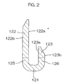
- FIG. 2 is a schematic transverse section showing the arrangement of piercing protrusion 122 and contacting protrusion 123 and is a sectional view along sectioning line II-II shown in FIG. 1(a).
- Piercing protrusions 122 and contacting protrusions 123 protrude upward from left side plate part 125 and right side plate part 126 with their respective inner surfaces 122a and 123a opposing each other, and the length of each contacting protrusion 123 is approximately 1/3rd the length of each piercing protrusion 122.
- the tip parts of piercing protrusion 122 and contacting protrusion 123 are respectively provided with tapered shapes that narrow towards the tips by gradually inclining from outer surfaces 122b and 123b to inner surfaces 122a and 123a and gradually inclining from the respective side edges towards the tip.
- the distance from outer surface 122b of piercing protrusion 122 to outer surface 123b of contacting protrusion 123 is approximately 0. 9mm in the width direction of bottom plate part 121.
- the tip parts of piercing protrusion 122 and contacting protrusion 123 are not limited to those described above and various types of chamfering may be applied as necessary.
- piercing protrusion 122 and contacting protrusion 123 serve as attachment parts for attachment to a flat cable, and in the attachment process, piercing protrusion 122 and contacting protrusion 123 are penetrated into the flat cable.
- tip parts of piercing protrusion 122 and contacting protrusion 123 have sharp shapes as described above, both protrusions can be penetrated readily into the flat cable.
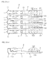
- FIG. 3 (a) andFIG. 3 (b) are diagrams showing the arrangement of a flat cable 3 with piercing contacts, with FIG. 3 (a) being a plan view and FIG. 3 (b) being a side view along arrow C shown in FIG. 3(a).
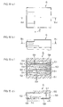
- FIG. 4 (a) and FIG. 4(b) are schematic transverse sections showing an example of a state of attachment of a piercing protrusion 122 and a contacting protrusion 123 of piercing contact 1 to flat cable 2 and are sectional views along sectioning line IV-IV shown in FIG. 3(a).
- Flat cable 3 with piercing contacts includes a plurality (five in the present embodiment) of piercing contacts 1 and a flat cable 2.
- Flat cable 2 has an arrangement wherein a plurality (five in the present embodiment) of belt-like conductors 21 are aligned at equal intervals on a single plane and covered by an insulating sheath 22.
- This flat cable 2 is a so-called FFC (Flexible Flat Cable).
- At parts between the five belt-like conductors 21 at the tip of flat cable 2 are respectively formed notches 23, with which insulating sheath 22 is notched in the longitudinal direction of belt-like conductors 21.
- Each notch 23 has a length such that it extends close to the rear end of a piercing contact 1 in the state in which piercing contacts 1 are attached.
- the fivepiercing contacts 1 are alignedat equal intervals, the five belt-like conductors 21 of flat cable 2 are made to respectively oppose piercing parts 12 of the respective piercing contacts 1 from above, and piercing protrusions 122 of the respective piercing parts 12 are pierced through insulating sheath 22 andbelt-like conductors 21 of flat cable 2 andprotruded upward from flat cable 2.
- contacting protrusions 123 of each piercing part 12 are pierced through insulating sheath 22 of flat cable 2 and put in contact with belt-like conductor 21.
- each piercing protrusion 122 and contacting protrusion 123 hold flat cable 2
- piercing protrusion 122 is pierced through flat cable 2 and then being bent and pressed towards the tip of contacting protrusion 123
- piercing protrusion 122 is pierced through insulating sheath 22 again from above and put in contact with belt-like conductor 21, and belt-like conductor 21 is clamped by the tip part of piercing protrusion 122 and the tip part of contacting protrusion 123 as shown in FIG. 4(a).
- the tip part of piercing protrusion 122 and the tip part of contacting protrusion 123 may be put in mutual contact within the range of the thickness of belt-like conductor 21.
- flat cable 2 may be held by contacting protrusion 123 being pierced through belt-like conductor 21 and the tip part of piercing protrusion 122 and the tip part of contacting protrusion 123 being put in contact with each other.
- the bending of piercing protrusion 122 may be achieved by curving as shown in FIG. 4 (a) and FIG. 4 (b) or may be achieved by inflecting.
- the width of a contact is narrower than the width of a belt-like conductor, and with piercing contact 1, by providing an arrangement with which the tip parts of piercing protrusion 122 and contacting protrusion 123 are attached to flat cable 2 upon being made to face each other, the width of bottom plate part 121 is made as narrow as possible.
- the distance from outer surface 122b of piercing protrusion 122 to outer surface 123b of contacting protrusion 123 is set to approximately 0.9mm as mentioned above.
- each of piercing protrusion 122 and contacting protrusion 123 is set to approximately 0.2mm and the distance from inner surface 122a of piercing protrusion 122 to inner surface 123a of contactingprotrusion 123 is set to approximately 0.5mm.
- the distance from inner surface 122a of piercing protrusion 122 to inner surface 123a of contacting protrusion 123 is preferably no more than approximately 2.5 times of the thickness of each protrusion.
- the width of the belt-like conductor 21 of flat cable 2 is set to approximately 1.5mm.
- the distance from outer surface 122b of piercing protrusion 122 to outer surface 123b of contacting protrusion 123 is preferably no more than approximately 3/5th the width of belt-like conductor 21.
- An allowance of approximately 0.6mm (distance of no less than approximately 2/3rd of the distance from outer surface 122b to outer surface 123b) can thus be secured between the distance between piercing protrusion 122 and contacting protrusion 123 and the width of belt-like conductor 21 in electrically connecting (attaching) piercing contact 1 to flat cable 2.
- Both piercing protrusion 122 and contacting protrusion 123 can thus be made to contact belt-like conductor 21 securely and the attachment strength and reliability of electrical connection can be improved.
- each piercing protrusion 122 and each contacting protrusion 123 are aligned in a staggered manner on piercing part 12.
- Piercing protrusions 122 and contacting protrusions 123 can thus be distributed uniformly without bias towards one side edge at belt-like conductor 21. The strength of connection of piercing contact 1 to flat cable 2 can thus be improved.
- FIG. 5(a), FIG. 5(b), and FIG. 5(c) are drawings showing the arrangement of a piercing contact 4 of another embodiment of the present invention.
- FIG. 5 (a) is a plan view
- FIG. 5(b) is a side view along arrow D shown in FIG. 5(a)
- FIG. 5(c) is a side view showing the state in which a flat cable 2 is attached to piercing contact 4 of FIG. 5(b).
- Flat cable 3 with piercing contact can be arranged using this piercing contact 4 in place of piercing contact 1 described above.
- Piercing contact 4 contains a piercing part 42, which corresponds to piercing part 12 of piercing contact 1.
- Piercing part 42 includes a bottom plate part 421, a left side plate part 425 and a right side plate part 426, which are erected upwards from the left and right side edges, respectively, of bottomplate part 421, and four piercing protrusions 422 and four corresponding pairs of contacting protrusions 423, which are erected from the upper edges of left side plate part 425 and right side plate part 426.
- two piercing protrusions 422 and two pairs of contacting protrusions 423 are formed and these are aligned so that a piercing protrusion 422 and a pair of contacting protrusions 423 alternate.
- belt-like conductor 21 of flat cable 2 is positioned to face piercing part 42 of piercing contact 4 from above and piercing protrusions 422 of piercing part 42 are pierced through insulating sheath 22 and belt-like conductor 21 of flat cable 2 and protruded upwards from flat cable 2.
- the pairs of contacting protrusions 423 of piercing part 42 are pierced through insulating sheath 22 of flat cable 2 and penetrated into belt-like conductor 21.
- each piercing protrusion 422 is pressed from above and each piercing protrusion 422, which is protruded upward from flat cable 2, is thereby bent in an inverted U-like shape towards trough part 424 between the opposing pair of contacting protrusions 423 and then pressed further.
- Trough part 424 corresponds to the shape of a tip part of piercing protrusion 422 and the tip part of piercing protrusion 422 enters into trough part 424.
- piercing contact 4 With piercing contact 4, the distance between a piercing protrusion 422 and a trough part 424 that oppose each other is made the same as in the case of piercing contact 1. Also as described above, piercing contact 4 includes four piercing protrusions 422 and four pairs of contacting protrusions 423 and these are aligned in a staggered manner at piercing part 42. The area of contact of the respective protrusions with belt-like conductor 21 can thus be increased and, furthermore, piercing protrusions 422 and contacting protrusions 423 can be distributed uniformly without bias towards one side edge of belt-like conductor 21. The strength of connection of piercing contact 4 to flat cable 2 can thus be improved.
- Each of piercing contact 1 and piercing contact 4 may include protrusions that are formed by cutting and erecting inwards intermediate parts in the length direction of piercing protrusions 122 or piercing protrusions 422, or equipped with cut and upwardly erected parts at bottom plate part 121 or bottom plate part 421.
- FIG. 6 (a) , FIG. 6 (b) , FIG. 6 (c) , and FIG. 6 (d) are drawings showing the arrangement of a connector housing 5, with FIG. 6 (a) being a plan view, FIG. 6(b) being a side view along arrow E shown in FIG. 6(a), FIG. 6(c) being a sectional view along sectioning line VIc-VIc shown in FIG. 6 (b) , and FIG. 6 (d) being a sectional view along sectioning line VId-VId shown in FIG. 6(a).
- the left side in FIG. 6 (a) shall be referred to as the front side and right side shall be referred to as the rear side.
- Connector housing 5 is formed of a resin-molded article and, by being equipped with upper plate part 55, lower plate part 56, left side plate part 57, and right side plate part 58, has a space in its interior that passes through in the front/rear direction. In this space, fourpartitioningwalls 59, extending from the front end to near the rear end of connector housing 5, are provided at fixed intervals. By these four partitioning walls 59, the space inside connector housing 5 is partitioned into five contact attachment holes 51.
- cable inlet 53 is partitioned by upper plate part 55, lower plate part 56, left side plate part 57, and right side plate part 58
- five contact inlets 52 are partitioned by upper plate part 55, lower plate part 56, left side plate part 57, right side plate part 58, and partitioning walls 59.
- contact latching claws 54 facing the respective contact attachment holes 51, are equipped on the upper surface (inner surface) of lower plate part 56.
- FIG. 7 (a), FIG. 7(b), FIG. 7(c), and FIG. 7 (d) are drawings showing the arrangement of a flat cable 6 with connector, with FIG. 7(a) being a plan view, FIG. 7(b) being a side view along arrow F shown in FIG. 7(a), FIG. 7(c) being a sectional view along sectioning line VIIc-VIIc shown in FIG. 7(b), and FIG. 7 (d) being a sectional view along sectioning line VIId-VIId shown in FIG. 7(a).
- Flat cable 6 with connector comprises connector housing 5 and flat cable 3 with piercing contacts.
- Flat cable 3 with piercing contacts may be one that uses piercing contacts 1 or one that uses piercing contacts 4 (an arrangement using piercing contacts 1 is shown in FIG. 7 (a) to FIG. 7 (d)).
- the left side in FIG. 7(a) shall be referred to as the front side and right side shall be referred to as the rear side.
- through holes 111 of the respective piercing contacts 1 are matched with the respective contact inlets 52 along the longitudinal direction of piercing contacts 1.
- Flat cable 6 with connector is electrically connected, for example, to a wiring board 7 by being attached to a counterpart connector 8 that is fixed to wiring board 7.
- Counterpart connector 8 is not limited to that which is fixed to wiring board 7 and may instead be one that is attached to another cable.
- Counterpart connector 8 is a female type connector including a housing 81, in which a fitting indentation 81a is formed for fitting of flat cable 6 with connector, and rod-like contacts 82 (male contacts) , which are protruded inside fitting indentation 81a of housing 81.
- Flat cable 6 with connector is attached to counterpart connector 8 by inserting rod-like contacts 82 into contact inlets 52 and then into through holes 111 of piercing contacts 1.
- connector housing 5 and housing 81 become joined and positioning among rod-like contacts 82 and piercing contacts 1 is achieved.
- Flat cable 2 is thereby electrically connected to wiring board 7 via piercing contacts 1 and rod-like contacts 82.
- flat cable 2 was described as being an FFC (Flexible Flat Cable), other types of flat cables, such as an FPC (Flexible Printed Circuit) , may be used instead.
- piercing contact 1 (4) may be a male contact and connector housing 5 may be a female housing.
- piercing part 12 (42) may have an arrangement, which lacks left and right side plate parts 125 and 126 (425 and 426) and with which the respective protrusions protrude from bottom plate part 121 (421).
Landscapes
- Multi-Conductor Connections (AREA)
- Coupling Device And Connection With Printed Circuit (AREA)
- Insulated Conductors (AREA)
Applications Claiming Priority (2)
| Application Number | Priority Date | Filing Date | Title |
|---|---|---|---|
| JP2003375892 | 2003-11-05 | ||
| JP2003375892A JP2005141984A (ja) | 2003-11-05 | 2003-11-05 | ピアシング型コンタクト、ピアシング型コンタクト付き平形ケーブル及びコネクタ付き平形ケーブル並びにそれらの製造方法 |
Publications (2)
| Publication Number | Publication Date |
|---|---|
| EP1530263A1 true EP1530263A1 (de) | 2005-05-11 |
| EP1530263B1 EP1530263B1 (de) | 2007-08-08 |
Family
ID=34431278
Family Applications (1)
| Application Number | Title | Priority Date | Filing Date |
|---|---|---|---|
| EP04256805A Expired - Lifetime EP1530263B1 (de) | 2003-11-05 | 2004-11-04 | Durchstechender Kontakt, Flachkabel mit durchstechendem Kontakt, Flachkabel mit Verbinder und deren Herstellungsverfahren |
Country Status (5)
| Country | Link |
|---|---|
| EP (1) | EP1530263B1 (de) |
| JP (1) | JP2005141984A (de) |
| KR (1) | KR20050043695A (de) |
| CN (1) | CN1614819B (de) |
| DE (1) | DE602004008010T2 (de) |
Cited By (3)
| Publication number | Priority date | Publication date | Assignee | Title |
|---|---|---|---|---|
| DE102021128871A1 (de) | 2021-11-05 | 2023-05-11 | Erni International Ag | Steckverbinder, Steckverbinderanordnung, sowie ein Werkzeug und Verfahren zur Montage der Steckverbinderanordnung |
| US12341288B2 (en) | 2022-12-14 | 2025-06-24 | Lear Corporation | Electrical assembly |
| US12374816B2 (en) | 2022-11-21 | 2025-07-29 | Lear Corporation | Electrical assembly |
Families Citing this family (1)
| Publication number | Priority date | Publication date | Assignee | Title |
|---|---|---|---|---|
| CN110224242B (zh) * | 2016-06-21 | 2021-02-23 | 深圳市敏杰电子科技有限公司 | 刺破式端子和冲压带 |
Citations (7)
| Publication number | Priority date | Publication date | Assignee | Title |
|---|---|---|---|---|
| US3924917A (en) * | 1974-04-30 | 1975-12-09 | Elco Corp | Flat cable termination method and apparatus |
| US4066319A (en) * | 1974-04-30 | 1978-01-03 | Elco Corporation | Method and apparatus for flat conductor cable termination |
| US5137468A (en) * | 1990-05-09 | 1992-08-11 | Sumitomo Wiring Systems, Ltd. | Electrical connector for flexible plane-type conductor cable |
| US20010014553A1 (en) * | 2000-02-15 | 2001-08-16 | Yazaki Corporation | Terminal and connecting method of circuit body and the terminal |
| US20020127905A1 (en) * | 2001-03-07 | 2002-09-12 | Yazaki Corporation | Electrical connection terminal |
| JP2003142188A (ja) * | 2001-11-01 | 2003-05-16 | Jst Mfg Co Ltd | 平形柔軟ケーブルの電気接触子、電気接触子付き平形柔軟ケーブル及びその製造方法 |
| US20030106211A1 (en) * | 2000-12-15 | 2003-06-12 | Noritsugu Enomoto | Method of connecting flat cable and terminal |
-
2003
- 2003-11-05 JP JP2003375892A patent/JP2005141984A/ja not_active Withdrawn
-
2004
- 2004-11-03 CN CN2004100901201A patent/CN1614819B/zh not_active Expired - Fee Related
- 2004-11-04 EP EP04256805A patent/EP1530263B1/de not_active Expired - Lifetime
- 2004-11-04 DE DE602004008010T patent/DE602004008010T2/de not_active Expired - Fee Related
- 2004-11-05 KR KR1020040089715A patent/KR20050043695A/ko not_active Ceased
Patent Citations (7)
| Publication number | Priority date | Publication date | Assignee | Title |
|---|---|---|---|---|
| US3924917A (en) * | 1974-04-30 | 1975-12-09 | Elco Corp | Flat cable termination method and apparatus |
| US4066319A (en) * | 1974-04-30 | 1978-01-03 | Elco Corporation | Method and apparatus for flat conductor cable termination |
| US5137468A (en) * | 1990-05-09 | 1992-08-11 | Sumitomo Wiring Systems, Ltd. | Electrical connector for flexible plane-type conductor cable |
| US20010014553A1 (en) * | 2000-02-15 | 2001-08-16 | Yazaki Corporation | Terminal and connecting method of circuit body and the terminal |
| US20030106211A1 (en) * | 2000-12-15 | 2003-06-12 | Noritsugu Enomoto | Method of connecting flat cable and terminal |
| US20020127905A1 (en) * | 2001-03-07 | 2002-09-12 | Yazaki Corporation | Electrical connection terminal |
| JP2003142188A (ja) * | 2001-11-01 | 2003-05-16 | Jst Mfg Co Ltd | 平形柔軟ケーブルの電気接触子、電気接触子付き平形柔軟ケーブル及びその製造方法 |
Non-Patent Citations (1)
| Title |
|---|
| PATENT ABSTRACTS OF JAPAN vol. 2003, no. 09 3 September 2003 (2003-09-03) * |
Cited By (3)
| Publication number | Priority date | Publication date | Assignee | Title |
|---|---|---|---|---|
| DE102021128871A1 (de) | 2021-11-05 | 2023-05-11 | Erni International Ag | Steckverbinder, Steckverbinderanordnung, sowie ein Werkzeug und Verfahren zur Montage der Steckverbinderanordnung |
| US12374816B2 (en) | 2022-11-21 | 2025-07-29 | Lear Corporation | Electrical assembly |
| US12341288B2 (en) | 2022-12-14 | 2025-06-24 | Lear Corporation | Electrical assembly |
Also Published As
| Publication number | Publication date |
|---|---|
| CN1614819A (zh) | 2005-05-11 |
| CN1614819B (zh) | 2010-11-24 |
| DE602004008010D1 (de) | 2007-09-20 |
| KR20050043695A (ko) | 2005-05-11 |
| EP1530263B1 (de) | 2007-08-08 |
| JP2005141984A (ja) | 2005-06-02 |
| DE602004008010T2 (de) | 2008-04-24 |
Similar Documents
| Publication | Publication Date | Title |
|---|---|---|
| US7101228B2 (en) | Electrical connector for memory modules | |
| US7802994B1 (en) | Combination of connector assembly and two printed circuit boards | |
| JP3320378B2 (ja) | 電気コネクタ | |
| US4270831A (en) | Electric terminal for press-in connection with conductors | |
| US5415562A (en) | Pressure welding connector | |
| WO1986001946A1 (en) | Double row electrical connector | |
| CN1096124C (zh) | 具有位于不同插入深度的接头的电连接器 | |
| WO2005020381A1 (en) | Board mounted electrical connector assembly | |
| JP2836463B2 (ja) | 圧接ジョイントコネクタ | |
| CN112563780B (zh) | 连接器和连接方法 | |
| US7112072B2 (en) | Ground bus for an electrical connector | |
| EP0926764A2 (de) | Elektrischer Kontakt für flexibles Flachkabel | |
| US7188408B2 (en) | Method of making a straddle mount connector | |
| US6309223B1 (en) | Terminal assembly for flexible circuit strip | |
| US6692273B1 (en) | Straddle mount connector | |
| US20100151709A1 (en) | Plug-in connector for circuit boards | |
| US6416349B1 (en) | IDC connector | |
| JP4084292B2 (ja) | 同軸ケーブルの圧接構造 | |
| US6171134B1 (en) | Multiple conductor cable connector | |
| KR20060135054A (ko) | 커넥터 및 그 결선 방법 | |
| EP1530263A1 (de) | Durchstechender Kontakt, Flachkabel mit durchstechendem Kontakt, Flachkabel mit Verbinder und deren Herstellungsverfahren | |
| EP0346104B1 (de) | Kontaktverbinder für Schaltplatte | |
| US20090311906A1 (en) | Cable assembly with jumper function | |
| JP4579949B2 (ja) | 接続端子の接続構造及び接続方法 | |
| EP1524726A1 (de) | Connecteur électrique pour câble plat et câble plat avec un tel connecteur |
Legal Events
| Date | Code | Title | Description |
|---|---|---|---|
| PUAI | Public reference made under article 153(3) epc to a published international application that has entered the european phase |
Free format text: ORIGINAL CODE: 0009012 |
|
| AK | Designated contracting states |
Kind code of ref document: A1 Designated state(s): AT BE BG CH CY CZ DE DK EE ES FI FR GB GR HU IE IS IT LI LU MC NL PL PT RO SE SI SK TR |
|
| AX | Request for extension of the european patent |
Extension state: AL HR LT LV MK YU |
|
| 17P | Request for examination filed |
Effective date: 20051011 |
|
| AKX | Designation fees paid |
Designated state(s): DE FR GB |
|
| 17Q | First examination report despatched |
Effective date: 20051104 |
|
| GRAP | Despatch of communication of intention to grant a patent |
Free format text: ORIGINAL CODE: EPIDOSNIGR1 |
|
| GRAS | Grant fee paid |
Free format text: ORIGINAL CODE: EPIDOSNIGR3 |
|
| GRAA | (expected) grant |
Free format text: ORIGINAL CODE: 0009210 |
|
| RIN1 | Information on inventor provided before grant (corrected) |
Inventor name: SASAKI, SHOICHI, C/O NAGOYA ENGINEERING CENTER OF Inventor name: NISHIKAWA, NAOTO, C/O NAGOYA ENGINEERING CENTER OF Inventor name: CHIRAN, KIYOHIKO, C/O NAGOYA ENGINEERING CENTER OF |
|
| AK | Designated contracting states |
Kind code of ref document: B1 Designated state(s): DE FR GB |
|
| RAP1 | Party data changed (applicant data changed or rights of an application transferred) |
Owner name: J.S.T. MFG. CO., LTD. |
|
| REG | Reference to a national code |
Ref country code: GB Ref legal event code: FG4D |
|
| REF | Corresponds to: |
Ref document number: 602004008010 Country of ref document: DE Date of ref document: 20070920 Kind code of ref document: P |
|
| ET | Fr: translation filed | ||
| PLBE | No opposition filed within time limit |
Free format text: ORIGINAL CODE: 0009261 |
|
| STAA | Information on the status of an ep patent application or granted ep patent |
Free format text: STATUS: NO OPPOSITION FILED WITHIN TIME LIMIT |
|
| 26N | No opposition filed |
Effective date: 20080509 |
|
| PGFP | Annual fee paid to national office [announced via postgrant information from national office to epo] |
Ref country code: DE Payment date: 20081103 Year of fee payment: 5 |
|
| PG25 | Lapsed in a contracting state [announced via postgrant information from national office to epo] |
Ref country code: DE Free format text: LAPSE BECAUSE OF NON-PAYMENT OF DUE FEES Effective date: 20100601 |
|
| PGFP | Annual fee paid to national office [announced via postgrant information from national office to epo] |
Ref country code: FR Payment date: 20101123 Year of fee payment: 7 |
|
| PGFP | Annual fee paid to national office [announced via postgrant information from national office to epo] |
Ref country code: GB Payment date: 20101103 Year of fee payment: 7 |
|
| GBPC | Gb: european patent ceased through non-payment of renewal fee |
Effective date: 20111104 |
|
| REG | Reference to a national code |
Ref country code: FR Ref legal event code: ST Effective date: 20120731 |
|
| PG25 | Lapsed in a contracting state [announced via postgrant information from national office to epo] |
Ref country code: GB Free format text: LAPSE BECAUSE OF NON-PAYMENT OF DUE FEES Effective date: 20111104 |
|
| PG25 | Lapsed in a contracting state [announced via postgrant information from national office to epo] |
Ref country code: FR Free format text: LAPSE BECAUSE OF NON-PAYMENT OF DUE FEES Effective date: 20111130 |