EP1530190A2 - Procédé et appareil de commande d'un panneau d'affichage à plasma - Google Patents
Procédé et appareil de commande d'un panneau d'affichage à plasma Download PDFInfo
- Publication number
- EP1530190A2 EP1530190A2 EP04025661A EP04025661A EP1530190A2 EP 1530190 A2 EP1530190 A2 EP 1530190A2 EP 04025661 A EP04025661 A EP 04025661A EP 04025661 A EP04025661 A EP 04025661A EP 1530190 A2 EP1530190 A2 EP 1530190A2
- Authority
- EP
- European Patent Office
- Prior art keywords
- sustain
- drive unit
- electrode
- discharge
- unified
- Prior art date
- Legal status (The legal status is an assumption and is not a legal conclusion. Google has not performed a legal analysis and makes no representation as to the accuracy of the status listed.)
- Ceased
Links
- 238000000034 method Methods 0.000 title claims abstract description 22
- 230000000977 initiatory effect Effects 0.000 claims abstract description 19
- 239000000758 substrate Substances 0.000 description 22
- 239000003990 capacitor Substances 0.000 description 5
- 230000004888 barrier function Effects 0.000 description 4
- 238000010586 diagram Methods 0.000 description 4
- CPLXHLVBOLITMK-UHFFFAOYSA-N magnesium oxide Inorganic materials [Mg]=O CPLXHLVBOLITMK-UHFFFAOYSA-N 0.000 description 4
- 239000000395 magnesium oxide Substances 0.000 description 4
- AXZKOIWUVFPNLO-UHFFFAOYSA-N magnesium;oxygen(2-) Chemical compound [O-2].[Mg+2] AXZKOIWUVFPNLO-UHFFFAOYSA-N 0.000 description 4
- 239000013256 coordination polymer Substances 0.000 description 3
- 229910000838 Al alloy Inorganic materials 0.000 description 1
- 230000008021 deposition Effects 0.000 description 1
- 230000008030 elimination Effects 0.000 description 1
- 238000003379 elimination reaction Methods 0.000 description 1
- 239000007789 gas Substances 0.000 description 1
- 239000011521 glass Substances 0.000 description 1
- 239000011261 inert gas Substances 0.000 description 1
- 239000000463 material Substances 0.000 description 1
- 229910052751 metal Inorganic materials 0.000 description 1
- 239000002184 metal Substances 0.000 description 1
- 238000012986 modification Methods 0.000 description 1
- 230000004048 modification Effects 0.000 description 1
- 238000011084 recovery Methods 0.000 description 1
- 230000002459 sustained effect Effects 0.000 description 1
Images


Classifications
-
- G—PHYSICS
- G09—EDUCATION; CRYPTOGRAPHY; DISPLAY; ADVERTISING; SEALS
- G09G—ARRANGEMENTS OR CIRCUITS FOR CONTROL OF INDICATING DEVICES USING STATIC MEANS TO PRESENT VARIABLE INFORMATION
- G09G3/00—Control arrangements or circuits, of interest only in connection with visual indicators other than cathode-ray tubes
- G09G3/20—Control arrangements or circuits, of interest only in connection with visual indicators other than cathode-ray tubes for presentation of an assembly of a number of characters, e.g. a page, by composing the assembly by combination of individual elements arranged in a matrix no fixed position being assigned to or needed to be assigned to the individual characters or partial characters
- G09G3/22—Control arrangements or circuits, of interest only in connection with visual indicators other than cathode-ray tubes for presentation of an assembly of a number of characters, e.g. a page, by composing the assembly by combination of individual elements arranged in a matrix no fixed position being assigned to or needed to be assigned to the individual characters or partial characters using controlled light sources
- G09G3/28—Control arrangements or circuits, of interest only in connection with visual indicators other than cathode-ray tubes for presentation of an assembly of a number of characters, e.g. a page, by composing the assembly by combination of individual elements arranged in a matrix no fixed position being assigned to or needed to be assigned to the individual characters or partial characters using controlled light sources using luminous gas-discharge panels, e.g. plasma panels
- G09G3/288—Control arrangements or circuits, of interest only in connection with visual indicators other than cathode-ray tubes for presentation of an assembly of a number of characters, e.g. a page, by composing the assembly by combination of individual elements arranged in a matrix no fixed position being assigned to or needed to be assigned to the individual characters or partial characters using controlled light sources using luminous gas-discharge panels, e.g. plasma panels using AC panels
- G09G3/296—Driving circuits for producing the waveforms applied to the driving electrodes
-
- G—PHYSICS
- G09—EDUCATION; CRYPTOGRAPHY; DISPLAY; ADVERTISING; SEALS
- G09G—ARRANGEMENTS OR CIRCUITS FOR CONTROL OF INDICATING DEVICES USING STATIC MEANS TO PRESENT VARIABLE INFORMATION
- G09G3/00—Control arrangements or circuits, of interest only in connection with visual indicators other than cathode-ray tubes
- G09G3/20—Control arrangements or circuits, of interest only in connection with visual indicators other than cathode-ray tubes for presentation of an assembly of a number of characters, e.g. a page, by composing the assembly by combination of individual elements arranged in a matrix no fixed position being assigned to or needed to be assigned to the individual characters or partial characters
- G09G3/22—Control arrangements or circuits, of interest only in connection with visual indicators other than cathode-ray tubes for presentation of an assembly of a number of characters, e.g. a page, by composing the assembly by combination of individual elements arranged in a matrix no fixed position being assigned to or needed to be assigned to the individual characters or partial characters using controlled light sources
- G09G3/28—Control arrangements or circuits, of interest only in connection with visual indicators other than cathode-ray tubes for presentation of an assembly of a number of characters, e.g. a page, by composing the assembly by combination of individual elements arranged in a matrix no fixed position being assigned to or needed to be assigned to the individual characters or partial characters using controlled light sources using luminous gas-discharge panels, e.g. plasma panels
- G09G3/288—Control arrangements or circuits, of interest only in connection with visual indicators other than cathode-ray tubes for presentation of an assembly of a number of characters, e.g. a page, by composing the assembly by combination of individual elements arranged in a matrix no fixed position being assigned to or needed to be assigned to the individual characters or partial characters using controlled light sources using luminous gas-discharge panels, e.g. plasma panels using AC panels
- G09G3/291—Control arrangements or circuits, of interest only in connection with visual indicators other than cathode-ray tubes for presentation of an assembly of a number of characters, e.g. a page, by composing the assembly by combination of individual elements arranged in a matrix no fixed position being assigned to or needed to be assigned to the individual characters or partial characters using controlled light sources using luminous gas-discharge panels, e.g. plasma panels using AC panels controlling the gas discharge to control a cell condition, e.g. by means of specific pulse shapes
- G09G3/294—Control arrangements or circuits, of interest only in connection with visual indicators other than cathode-ray tubes for presentation of an assembly of a number of characters, e.g. a page, by composing the assembly by combination of individual elements arranged in a matrix no fixed position being assigned to or needed to be assigned to the individual characters or partial characters using controlled light sources using luminous gas-discharge panels, e.g. plasma panels using AC panels controlling the gas discharge to control a cell condition, e.g. by means of specific pulse shapes for lighting or sustain discharge
Definitions
- the present invention relates to a plasma display panel, and more particularly, to an apparatus and a method of driving a plasma display panel.
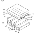
- FIG. 1 is a perspective diagram of a general AC type surface discharge plasma display panel.
- a general AC type surface discharge plasma display panel consists of front and rear substrates 122 and 124 formed of a transparent glass based material.
- a plurality of barrier ribs 126 are provided to the rear substrate 1 24 by thick film printing to maintain the gap from the front substrate 122.
- a plurality of the barrier ribs 126 leave a distance of 400 ⁇ m from each other and a width of each of the barrier ribs 126 amounts to 50 ⁇ m.
- an R/G/B fluorescent layer having a thickness of 10 ⁇ 30 ⁇ m covers each of the X-electrodes to form a luminous layer 136.
- the Y- and Z-electrodes are formed about several hundreds mm by deposition of ITO, SnO, or the like to extend parallel to each other.
- the row electrodes Yi and Zi adjacent to each other form a pair to configure a row electrode pair (Yi, Zi).
- Metal based bus electrodes ⁇ i and ⁇ i are formed narrower than the row electrodes Yi and Zi to adhere closely to the row electrodes Yi and Zi, respectively.
- the bus electrodes ⁇ i and ⁇ i are supplementary electrodes for compensating conductivity of the row electrodes Yi and Zi.
- a dielectric layer 130 is formed about 20 ⁇ 30 ⁇ m thick to protect the row electrodes Yi and Zi.
- An MgO layer 132 formed of magnesium oxide (MgO) is stacked about several hundreds nm thick on the dielectric layer 13.
- the front and rear substrates 122 and 124 are bonded to each other.
- a surface of the MgO layer 132 is dehydrated by baking.
- mixed inert gas including 3 ⁇ 7% NeXe gas thereof is injected into the discharge space 1 28 at 400 ⁇ 600 torr.
- a unit luminous area is defined as a pixel cell P(i, j) centering around an intersection point between the electrodes Yi and Zi and the electrode Xj.
- the pixel cell P(i , j) when a wall voltage is generated from addressing discharge between the electrodes Xj and Yi, sustain pulse are applied between the electrodes Yi and Zi to maintain discharge so that the fluorescent body of the luminous layer 136 can be excited to emit light. And, the light emission can be controlled by the voltage application between the electrodes Xj, Yi, and Zi via selection, maintain, and elimination of the luminous discharge of the pixel cell P(i, j).
- the sustain pulses are alternately applied to the electrode Yi and the electrode Zi, respectively. Namely, if the sustain pulse is applied to the electrode Yi, it is not applied to the electrode Zi. And, if the sustain pulse is applied to the electrode Zi, it is not applied to the electrode Yi. Thus, the surface discharge using AC can be maintained.
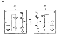
- FIG. 2 is a circuit diagram of a general sustain pulse drive unit for supplying sustain pulses to Y-electrode and Z-electrode.
- FIG. 3 is a waveform graph of sustain pulses generated from the sustain pulse drive unit according to the related art shown in FIG. 2.
- a general sustain pulse drive unit includes an energy recovery circuit for being efficiently supplied with energy necessary for generating a high-voltage sustain pulse.
- the general sustain pulse drive unit consists of a Y-electrode sustain pulse drive circuit and a Y-electrode sustain pulse drive circuit. And, a circuit configuration of a Y-electrode sustain pulse drive circuit 210 is identical to that of a Z-electrode sustain pulse drive circuit 220.
- the general sustain pulse drive unit operates according to a 4-steps operational sequence.
- a first switch S1 included in the Y-electrode sustain pulse drive unit 210 is turned on, while second to fourth switches S2 to S4 are turned off.
- energy stored in a capacitor CS is supplied to another capacitor CP so that a sustain pulse voltage (hereinafter abbreviated VPY) applied to a Y-electrode can rise.
- VPY sustain pulse voltage
- the latter capacitor CP indicates capacitance by discharge cells of a plasma display panel.
- the first and second switches S1 and S2 are turned on, while the third and fourth switches S3 and S4 are turned off.
- the VPY maintains a sustain voltage VS.
- the third switch S3 is turned on, while the first, second, and fourth switches S1, S2, and S4 are turned off. Hence, the energy stored in the latter capacitor CP is discharged to the former capacitor CS to be recovered and the VPY drops.
- the sustain pulse voltage is provided to be applied to the Y-electrode.
- An operation of the Z-electrode sustain pulse drive unit 220 is as good as that of the Y-electrode sustain pulse drive unit 210.
- a waveform of the sustain pulse applied to the Y- or Z-electrode follows that shown in FIG. 3.
- FIG. 4 is a layout of a circuit board of a drive device for a plasma display panel according to a related art.
- a central arithmetic logical unit 410 for controlling video signal processing is located at a central part of a plasma display panel 400.
- a substrate 420 having a Y-electrode sustain pulse drive unit 210 formed thereon and a substrate 430 having a Z-electrode sustain pulse drive unit 220 formed thereon are provided to left and right sides of the central arithmetic logical unit 410, respectively.
- a scan drive substrate 440 is arranged next to the substrate 420 having the Y-electrode sustain pulse drive unit 210 formed thereon.
- a data drive substrate 400 for applying a data pulse to an X-electrode is arranged on the plasma display panel 400.
- FIG. 5 is a waveform graph of a drive waveform outputted from a drive device of a plasma display panel according to a related art.
- a drive waveform applied to the Y- or Z-electrode is divided into a reset section for new addressing, an addressing section, and a sustain section.
- the sustain section of the waveform in FIG. 5 is provided by the operations of the Y-electrode sustain drive unit 210 and the Z-electrode sustain drive unit 220 which were explained with reference to FIG. 2 and FIG. 3.
- the substrate 420 having the Y-electrode sustain pulse drive unit 210 formed thereon and the substrate 430 having the Z-electrode sustain pulse drive unit 220 formed thereon are provided to the left and right sides of the central arithmetic logical unit 410, respectively, an overall volume of the device increases.
- an object of the present invention is to solve at least the problems and disadvantages of the background art.
- An object of the present invention is to provide an apparatus for driving a plasma display panel and method thereof, by which drive efficiency is raised and by which an overall volume of the apparatus can be reduced.
- an apparatus of driving an AC surface discharge type plasma display panel which includes X-, Y-, and Z-electrodes for discharge initiation and discharge sustain, includes a central arithmetic logical unit, a reset drive unit, a data drive unit, a scan drive unit, and a sustain drive unit wherein the sustain drive unit includes a unified sustain drive unit.
- an apparatus of driving an AC surface discharge type plasma display panel which includes X-, Y-, and Z-electrodes for discharge initiation and discharge sustain, includes a central arithmetic logical unit controlling processing of a video signal displayed via the plasma display panel, a unified sustain drive unit applying a pulse for performing a sustain function, a reset drive unit and a scan drive unit applying a pulse for performing a reset function and an addressing function among drive waveforms of the plasma display panel, and a data drive unit applying a data pulse to the X-electrode during an addressing process.
- a method of driving an AC surface discharge type plasma display panel which includes X-, Y-, and Z-electrodes for discharge initiation and discharge sustain, includes a discharge initiation step and a discharge sustain step wherein in the discharge sustain step, a ground potential is applied to the Y-electrode and sustain pulses having alternate polarities are applied to the Z-electrode.
- a method of driving an AC surface discharge type plasma display panel which includes X-, Y-, and Z-electrodes for discharge initiation and discharge sustain, includes a discharge initiation step and a discharge sustain step wherein in the discharge sustain step, a constant DC potential is applied to the Y-electrode and sustain pulses having alternate polarities are applied to the Z-electrode.
- the sustain drive unit is included, whereby the drive efficiency is raised, the drive circuit is simplified, and the overall volume is reduced.
- FIG. 1 is a perspective diagram of a general AC type surface discharge plasma display panel.
- FIG. 2 is a circuit diagram of a general sustain pulse drive unit for supplying sustain pulses to Y-electrode and Z-electrode.
- FIG. 3 is a waveform graph of sustain pulses generated from the sustain pulse drive Unit according to the related art shown in FIG. 2.
- FIG. 4 is a layout of a circuit board of a drive device for a plasma display panel according to a related art.
- FIG. 5 is a waveform graph of a drive waveform outputted from a drive device of a plasma display panel according to a related art.
- FIG. 6 is a layout of an apparatus for driving a plasma display panel according to the present invention.
- FIG. 7 is a waveform graph of a drive waveform outputted from an apparatus for driving a plasma display panel according to the present invention.
- an apparatus of driving an AC surface discharge type plasma display panel which includes X-, Y-, and Z-electrodes for discharge initiation and discharge sustain, includes a central arithmetic logical unit, a reset drive unit, a data drive unit, a scan drive unit, and a sustain drive unit wherein the sustain drive unit includes a unified sustain drive unit.
- the unified sustain drive unit applies sustain pulses having alternate polarities to the Z-electrode.
- the Y-electrode stays at a ground level while the unified sustain drive unit applies the sustain pulses having the alternate polarities to the Z-electrode.
- the Y-electrode stays at a constant DC level while the unified sustain drive unit applies the sustain pulses having the alternate polarities to the Z-electrode.
- either the reset drive unit or the scan drive unit applies a signal at a ground level to the Y-electrode while the unified sustain drive unit applies the sustain pulses having the alternate polarities to the Z-electrode.
- either the reset drive unit or the scan drive unit applies a signal at a constant DC level to the Y-electrode while the unified sustain drive unit applies the sustain pulses having the alternate polarities to the Z-electrode.
- an apparatus of driving an AC surface discharge type plasma display panel which includes X-, Y-, and Z-electrodes for discharge initiation and discharge sustain, includes a central arithmetic logical unit controlling processing of a video signal displayed via the plasma display panel, a unified sustain drive unit applying a pulse for performing a sustain function, a reset drive unit and a scan drive unit applying a pulse for performing a reset function and an addressing function among drive waveforms of the plasma display panel, and a data drive unit applying a data pulse to the X-electrode during an addressing process.
- the unified sustain drive unit applies sustain pulses having alternate polarities to the Z-electrode.
- the Y-electrode stays at a ground level while the unified sustain drive unit applies the sustain pulses having the alternate polarities to the Z-electrode.
- the Y-electrode stays at a constant DC level while the unified sustain drive unit applies the sustain pulses having the alternate polarities to the Z-electrode.
- either the reset drive unit or the scan drive unit applies a signal at a ground level to the Y-electrode while the unified sustain drive unit applies the sustain pulses having the alternate polarities to the Z-electrode.
- either the reset drive unit or the scan drive unit applies a signal at a constant DC level to the Y-electrode while the unified sustain drive unit applies the sustain pulses having the alternate polarities to the Z-electrode.
- a method of driving an AC surface discharge type plasma display panel which includes X-, Y-, and Z-electrodes for discharge initiation and discharge sustain, includes a discharge initiation step and a discharge sustain step wherein in the discharge sustain step, a ground potential is applied to the Y-electrode and sustain pulses having alternate polarities are applied to the Z-electrode.
- the applying the sustain pulses having the alternate polarities to the Z-electrode is performed by a unified sustain drive unit.
- the applying the ground potential to the Y-electrode is performed by either a reset drive unit or a scan drive unit.
- a method of driving an AC surface discharge type plasma display panel which includes X-, Y-, and Z-electrodes for discharge initiation and discharge sustain, includes a discharge initiation step and a discharge sustain step wherein in the discharge sustain step, a constant DC potential is applied to the Y-electrode and sustain pulses having alternate polarities are applied to the Z-electrode.
- the applying the sustain pulses having the alternate polarities to the Z-electrode is performed by a unified sustain drive unit.
- the applying the constant DC potential to the Y-electrode is performed by either a reset drive unit or a scan drive unit.
- FIG. 6 is a layout of an apparatus for driving a plasma display panel according to the present invention.
- an apparatus for driving a plasma display panel according to the present invention includes a central arithmetic logical unit 610, a unified sustain drive unit 620, a reset drive unit 640, and a data drive unit 650.
- the central arithmetic logical unit 610 controls the processing of a video signal displayed on a plasma display panel.
- the unified sustain drive unit 620 outputs sustain pulses, of which magnitude are equal to each other and of which polarities alternate, to a Z-electrode.
- the unified sustain drive unit 620 applies the sustain pulses, of which magnitude are equal to each other and of which polarities alternate, to the Z-electrode, it is able to provide a Y-electrode sustain drive unit 210 and a Z-electrode sustain drive unit 220, which were separated from each other in the related art, to one substrate.
- the sustain pulse impression can be performed via the unified sustain drive unit 620 provided on one substrate.
- the reset drive unit 630 and the scan drive unit 640 apply pulses for carrying out a reset function and an addressing function of the plasma display panel to a Y-electrode, respectively.
- the reset drive unit 630 and the scan drive unit 640 output signals of OV or constant DC level each to bring about AC surface discharge while the sustain drive unit 620 applies the sustain pulses having alternate polarities to the Z-electrode.
- the data drive unit 650 applies a data pulse to an X-electrode during an addressing process.
- FIG. 7 is a waveform graph of a drive waveform generated from an apparatus for driving a plasma display panel according to the present invention.
- a drive waveform applied to a plasma display panel includes specific waveforms differing from each other during reset, addressing, and sustain sections, respectively.
- the drive waveform of the present invention is different from that of the related art during the sustain section in that sustain pulses having the alternate polarities are applied to a Z-electrode and that a Y-electrode maintains a ground level or a constant DC level.
- sustain pulses having the alternate polarities are applied to a Z-electrode and that a Y-electrode maintains a ground level or a constant DC level.
- waveforms of the reset and addressing sections are applied to the Y-electrode by the reset drive unit 630 and the addressing drive unit 640 of the drive apparatus shown in FIG. 6.
- a waveform of the sustain section is applied to the Z-electrode by the unified sustain drive unit 620 of the drive apparatus shown in FIG. 6.
- the unified sustain drive unit 620 generates the alternating sustain pulses so that the plasma display panel can maintain the discharge during the sustain section.
- the sustain waveform, as shown in FIG. 7, includes a plurality of alternate positive and negative rectangular waves, thereby enabling not to be applied to the Y-electrode but to be applied to the Z-electrode.
- the present invention enables to raise the drive efficiency in a manner of applying the sustain pulses to the Z-electrode by the unified sustain drive unit 620 instead of applying the sustain pulses to the Y-electrode via the substrate provided with the scan drive unit 640. And, the present invention unifies a pair of the related art sustain drive units 210 and 220 into one, thereby enabling to simplify the circuit configuration and to reduce the circuit volume.
Landscapes
- Engineering & Computer Science (AREA)
- Physics & Mathematics (AREA)
- Power Engineering (AREA)
- Plasma & Fusion (AREA)
- Computer Hardware Design (AREA)
- General Physics & Mathematics (AREA)
- Theoretical Computer Science (AREA)
- Control Of Indicators Other Than Cathode Ray Tubes (AREA)
- Control Of Gas Discharge Display Tubes (AREA)
Applications Claiming Priority (2)
| Application Number | Priority Date | Filing Date | Title |
|---|---|---|---|
| KR2003077937 | 2003-11-05 | ||
| KR1020030077937A KR100554415B1 (ko) | 2003-11-05 | 2003-11-05 | 플라즈마 표시 패널 구동장치 |
Publications (2)
| Publication Number | Publication Date |
|---|---|
| EP1530190A2 true EP1530190A2 (fr) | 2005-05-11 |
| EP1530190A3 EP1530190A3 (fr) | 2007-06-13 |
Family
ID=34431721
Family Applications (1)
| Application Number | Title | Priority Date | Filing Date |
|---|---|---|---|
| EP04025661A Ceased EP1530190A3 (fr) | 2003-11-05 | 2004-10-28 | Procédé et appareil de commande d'un panneau d'affichage à plasma |
Country Status (4)
| Country | Link |
|---|---|
| US (1) | US7456809B2 (fr) |
| EP (1) | EP1530190A3 (fr) |
| KR (1) | KR100554415B1 (fr) |
| CN (1) | CN100440281C (fr) |
Cited By (2)
| Publication number | Priority date | Publication date | Assignee | Title |
|---|---|---|---|---|
| EP1835483A3 (fr) * | 2006-03-14 | 2008-05-14 | Lg Electronics Inc. | Procédé de commande d'un appareil d'affichage à plasma |
| US7652640B2 (en) | 2005-07-12 | 2010-01-26 | Lg Electronics Inc. | Plasma display apparatus and method of driving the same |
Families Citing this family (1)
| Publication number | Priority date | Publication date | Assignee | Title |
|---|---|---|---|---|
| KR100701957B1 (ko) * | 2005-04-15 | 2007-03-30 | 엘지전자 주식회사 | 플라즈마 디스플레이 패널 |
Citations (2)
| Publication number | Priority date | Publication date | Assignee | Title |
|---|---|---|---|---|
| JPH08320667A (ja) | 1995-05-24 | 1996-12-03 | Fujitsu Ltd | プラズマパネルの駆動方法、駆動装置及び画像表示装置 |
| EP1065650A2 (fr) | 1999-06-30 | 2001-01-03 | Fujitsu Limited | Dispositif de commande et procédé de commande pour un panneau d'affichage à plasma |
Family Cites Families (4)
| Publication number | Priority date | Publication date | Assignee | Title |
|---|---|---|---|---|
| US6020687A (en) * | 1997-03-18 | 2000-02-01 | Fujitsu Limited | Method for driving a plasma display panel |
| JP4299497B2 (ja) * | 2002-05-16 | 2009-07-22 | 日立プラズマディスプレイ株式会社 | 駆動回路 |
| EP1376526A3 (fr) * | 2002-06-26 | 2004-12-08 | Pioneer Corporation | Circuit de commande d'affichage, Système de transfert de données et Dispositif de reception de données |
| KR100490620B1 (ko) * | 2002-11-28 | 2005-05-17 | 삼성에스디아이 주식회사 | 플라즈마 디스플레이 패널의 구동 방법 |
-
2003
- 2003-11-05 KR KR1020030077937A patent/KR100554415B1/ko not_active Expired - Fee Related
-
2004
- 2004-10-27 US US10/974,025 patent/US7456809B2/en not_active Expired - Fee Related
- 2004-10-28 CN CNB2004100868190A patent/CN100440281C/zh not_active Expired - Fee Related
- 2004-10-28 EP EP04025661A patent/EP1530190A3/fr not_active Ceased
Patent Citations (2)
| Publication number | Priority date | Publication date | Assignee | Title |
|---|---|---|---|---|
| JPH08320667A (ja) | 1995-05-24 | 1996-12-03 | Fujitsu Ltd | プラズマパネルの駆動方法、駆動装置及び画像表示装置 |
| EP1065650A2 (fr) | 1999-06-30 | 2001-01-03 | Fujitsu Limited | Dispositif de commande et procédé de commande pour un panneau d'affichage à plasma |
Cited By (2)
| Publication number | Priority date | Publication date | Assignee | Title |
|---|---|---|---|---|
| US7652640B2 (en) | 2005-07-12 | 2010-01-26 | Lg Electronics Inc. | Plasma display apparatus and method of driving the same |
| EP1835483A3 (fr) * | 2006-03-14 | 2008-05-14 | Lg Electronics Inc. | Procédé de commande d'un appareil d'affichage à plasma |
Also Published As
| Publication number | Publication date |
|---|---|
| KR100554415B1 (ko) | 2006-02-22 |
| US20050093469A1 (en) | 2005-05-05 |
| EP1530190A3 (fr) | 2007-06-13 |
| KR20050043147A (ko) | 2005-05-11 |
| CN1614664A (zh) | 2005-05-11 |
| US7456809B2 (en) | 2008-11-25 |
| CN100440281C (zh) | 2008-12-03 |
Similar Documents
| Publication | Publication Date | Title |
|---|---|---|
| JP3303134B2 (ja) | プラズマディスプレーパネルとその駆動装置及び方法 | |
| JPH09115450A (ja) | Ac型プラズマディスプレイパネルおよび駆動方法 | |
| US20040169621A9 (en) | Plasma display and driving method thereof | |
| JP2003015585A (ja) | プラズマディスプレイ及びその駆動方法 | |
| JP2003323150A (ja) | プラズマ表示装置の駆動方法 | |
| JP2002108283A (ja) | プラズマディスプレーパネルの駆動方法 | |
| US20020154074A1 (en) | Plasma display panel and driving method thereof | |
| US6278243B1 (en) | Electrode division surface discharge plasma display apparatus | |
| US7456809B2 (en) | Apparatus and method of driving a plasma display panel | |
| EP1635318A2 (fr) | Procédé et dispositif de récupération d'énergie pour un panneau d'affichage à plasma | |
| JP3644789B2 (ja) | プラズマディスプレイパネル及びその駆動方法 | |
| EP1607930A1 (fr) | Procede d'activation d'un ecran plasma | |
| US7928931B2 (en) | Plasma display apparatus | |
| JP4165051B2 (ja) | プラズマディスプレイ装置 | |
| US20060176247A1 (en) | Plasma display apparatus and driving method thereof | |
| KR100638211B1 (ko) | 플라즈마 디스플레이 패널 | |
| US7701146B2 (en) | Plasma display apparatus | |
| CN102037505A (zh) | 等离子显示装置以及等离子显示面板的驱动方法 | |
| KR100313112B1 (ko) | 플라즈마 표시 패널의 구동 방법 | |
| KR100539165B1 (ko) | 에너지 회수 회로부를 포함하는 플라즈마 디스플레이패널의 구동장치 | |
| JP2001068030A (ja) | 3電極型acプラズマディスプレイパネル | |
| WO2009096639A1 (fr) | Appareil d'affichage à plasma et procédé de commande | |
| US7999761B2 (en) | Plasma display apparatus and method of driving the same | |
| KR20060078566A (ko) | 플라즈마 디스플레이 패널 | |
| US20090085842A1 (en) | Plasma display apparatus |
Legal Events
| Date | Code | Title | Description |
|---|---|---|---|
| PUAI | Public reference made under article 153(3) epc to a published international application that has entered the european phase |
Free format text: ORIGINAL CODE: 0009012 |
|
| AK | Designated contracting states |
Kind code of ref document: A2 Designated state(s): AT BE BG CH CY CZ DE DK EE ES FI FR GB GR HU IE IT LI LU MC NL PL PT RO SE SI SK TR |
|
| AX | Request for extension of the european patent |
Extension state: AL HR LT LV MK |
|
| RIN1 | Information on inventor provided before grant (corrected) |
Inventor name: CHOI, JEONG PIL Inventor name: LIM, GEUN SOO |
|
| PUAL | Search report despatched |
Free format text: ORIGINAL CODE: 0009013 |
|
| AK | Designated contracting states |
Kind code of ref document: A3 Designated state(s): AT BE BG CH CY CZ DE DK EE ES FI FR GB GR HU IE IT LI LU MC NL PL PT RO SE SI SK TR |
|
| AX | Request for extension of the european patent |
Extension state: AL HR LT LV MK |
|
| RIC1 | Information provided on ipc code assigned before grant |
Ipc: G09G 3/288 20060101AFI20070508BHEP |
|
| 17P | Request for examination filed |
Effective date: 20071211 |
|
| AKX | Designation fees paid |
Designated state(s): DE FR GB NL |
|
| 17Q | First examination report despatched |
Effective date: 20080205 |
|
| STAA | Information on the status of an ep patent application or granted ep patent |
Free format text: STATUS: THE APPLICATION HAS BEEN REFUSED |
|
| 18R | Application refused |
Effective date: 20090331 |