EP1530049A1 - Vorrichtung zur Bestimmung der Geschossgeschwindigkeit, insbesondere im Mündungsbereich eines Waffenrohres - Google Patents
Vorrichtung zur Bestimmung der Geschossgeschwindigkeit, insbesondere im Mündungsbereich eines Waffenrohres Download PDFInfo
- Publication number
- EP1530049A1 EP1530049A1 EP04026010A EP04026010A EP1530049A1 EP 1530049 A1 EP1530049 A1 EP 1530049A1 EP 04026010 A EP04026010 A EP 04026010A EP 04026010 A EP04026010 A EP 04026010A EP 1530049 A1 EP1530049 A1 EP 1530049A1
- Authority
- EP
- European Patent Office
- Prior art keywords
- sensors
- weapon barrel
- projectile
- barrel
- recesses
- Prior art date
- Legal status (The legal status is an assumption and is not a legal conclusion. Google has not performed a legal analysis and makes no representation as to the accuracy of the status listed.)
- Withdrawn
Links
- 238000011156 evaluation Methods 0.000 claims abstract description 8
- 239000007789 gas Substances 0.000 description 5
- 239000010453 quartz Substances 0.000 description 4
- VYPSYNLAJGMNEJ-UHFFFAOYSA-N silicon dioxide Inorganic materials O=[Si]=O VYPSYNLAJGMNEJ-UHFFFAOYSA-N 0.000 description 4
- 239000011324 bead Substances 0.000 description 3
- 238000009434 installation Methods 0.000 description 3
- 238000005259 measurement Methods 0.000 description 3
- 239000007787 solid Substances 0.000 description 3
- 239000003380 propellant Substances 0.000 description 2
- 230000003321 amplification Effects 0.000 description 1
- 238000009530 blood pressure measurement Methods 0.000 description 1
- 230000006735 deficit Effects 0.000 description 1
- 230000004907 flux Effects 0.000 description 1
- 238000010438 heat treatment Methods 0.000 description 1
- 230000010354 integration Effects 0.000 description 1
- 238000004519 manufacturing process Methods 0.000 description 1
- 238000003199 nucleic acid amplification method Methods 0.000 description 1
- 239000000843 powder Substances 0.000 description 1
- 230000002123 temporal effect Effects 0.000 description 1
Images

Classifications
-
- G—PHYSICS
- G01—MEASURING; TESTING
- G01P—MEASURING LINEAR OR ANGULAR SPEED, ACCELERATION, DECELERATION, OR SHOCK; INDICATING PRESENCE, ABSENCE, OR DIRECTION, OF MOVEMENT
- G01P3/00—Measuring linear or angular speed; Measuring differences of linear or angular speeds
- G01P3/64—Devices characterised by the determination of the time taken to traverse a fixed distance
- G01P3/66—Devices characterised by the determination of the time taken to traverse a fixed distance using electric or magnetic means
- G01P3/665—Devices characterised by the determination of the time taken to traverse a fixed distance using electric or magnetic means for projectile velocity measurements
-
- F—MECHANICAL ENGINEERING; LIGHTING; HEATING; WEAPONS; BLASTING
- F41—WEAPONS
- F41A—FUNCTIONAL FEATURES OR DETAILS COMMON TO BOTH SMALLARMS AND ORDNANCE, e.g. CANNONS; MOUNTINGS FOR SMALLARMS OR ORDNANCE
- F41A21/00—Barrels; Gun tubes; Muzzle attachments; Barrel mounting means
- F41A21/32—Muzzle attachments or glands
Definitions
- a device for measuring the projectile velocity is on the mouth of a barrel of a gun high cadence known. This includes two arranged at a distance from each other on a support tube, to change a magnetic flux responsive sensors, which communicate with evaluation electronics stand. Each sensor has a coil pair of two coils and a shot magnetic circuit.
- DE 697 09 291 T2 (EP 0 840 087 B1) discloses means for controlling the initial speed of a projectile.
- a sensor means is provided, the one can measure the muzzle velocity related parameter. This is done with help the at least in or on the barrel mounted sensors, the higher pressure in the Gun run record, which is characterized by the heating of the propellant gases on the barrel established.
- sensors strain gauges are proposed, which are adapted are that they have contact with the gun barrel. This should be easy the expansions of Arms race can be measured. From the time difference between the registration the projectile passage through the two individual sensors becomes the movement and thus determines the speed of the projectile.
- the invention provides the object of another device for determining the projectile velocity.
- the invention is based on the idea, at least two spaced-apart sensors or integrate sensor pairs on or directly in the weapon barrel.
- sensors are preferably quartz sensors used in the form of longitudinal measuring dowels, either in a carrier ring on or around the Gun barrel or mounted directly in the barrel.
- the quartz sensors have the big one Advantage that you can convert even the smallest pressure changes into signals, yourself are very robust and fit, that is, in solid contact unverurgingbar to Weapon barrel can be integrated. Have mechanical loads of the weapon barrel this does not affect the measurement result of the indirect pressure measurement.
- the sensors In addition, they are not exposed directly to the gas pressure and in addition to the existing Housing installed in a solid structure.
- the integration of the sensors on or in the weapon barrel makes it possible to measure the muzzle velocity of full caliber and sub caliber - ammunition without impairment, for example, by the sabots on the measurement.
- the amplifier stage 7 can be dispensed with if the signal quantities of the sensors 2, 3 are to be regarded as adequate for further processing.
- the sensors 2, 3 are designed such that they fit snugly in the bores 4.1, 5.1 and have mechanical contact with the weapon barrel 1 via the carrier ring 4, 5.
- the carrier rings 4, 5 are preferably shrunk onto the weapon barrel 1.
- the gun barrel 1 at the provided points 9, 10 are cylindrically twisted, where passganau each of the cylindrical support ring 4, 5 is shrunk onto these cylindrical locations 9, 10.
- the entire inner surface of the carrier rings 4, 5 receives contact with the outer surface of the weapon barrel 1.
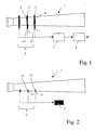
- the sensors 12, 13 are directly integrated in the barrel 1. These are in the Gun barrel 1 recesses 14, 15, preferably introduced as holes.
- the recesses 14, 15 can be both radial and tangential - or in the case of sensor pairs radial and tangential - be formed with respect to the tube axis.
- the sensors 12, 13 are preferably introduced from the outside into the recesses 14, 15.
- FIG. 3 Another possibility according to FIG. 3 is the diameter of the tube inner wall 1.1 almost fully exploit, the sensors 12, 13, not larger than this inner wall 1.1 may not be allowed to protrude into the barrel 1.
- the sensors 12, 13 are protected by a thin remainder of the pipe inner wall 14, so not be exposed directly to the gas pressure.
- the sensors 12, 13 are provided with at least one amplifier stage 7 Signal evaluation unit 8 downstream.
- the evaluation is carried out depending on the type and Use of the measurement in a known manner. For example, from the temporal Difference between the registration of the projectile passage by the two individual sensors the movement and thus the speed of a projectile not shown determined.
Landscapes
- Engineering & Computer Science (AREA)
- General Engineering & Computer Science (AREA)
- Physics & Mathematics (AREA)
- General Physics & Mathematics (AREA)
- Aiming, Guidance, Guns With A Light Source, Armor, Camouflage, And Targets (AREA)
- Measuring Fluid Pressure (AREA)
Abstract
Description
- Fig. 1
- eine schematische Darstellung einer Anordnung von Sensoren am Waffenrohr,
- Fig. 2
- eine schematische Darstellung der Anordnung der Sensoren direkt im Waffenrohr
- Fig. 3
- eine Querschnittdarstellung des Einbaus eines Sensors in das Waffenrohr.
Die Sensoren 2, 3 sind derart gestaltet, dass sie in den Bohrungen 4.1, 5.1 passgenau sitzen und über den Trägerring 4, 5 mechanischen Kontakt zum Waffenrohr 1 besitzen. Die Trägerringe 4, 5 sind vorzugsweise auf das Waffenrohr 1 aufgeschrumpft. Dazu kann das Waffenrohr 1 an den vorgesehenen Stellen 9, 10 zylindrisch überdreht werden, an denen passganau jeweils der zylindrische Trägerring 4, 5 auf diesen zylindrischen Stellen 9, 10 aufgeschrumpft wird. Dadurch erhält die ganze Innenfläche der Trägerringe 4, 5 Kontakt zur Außenfläche des Waffenrohres 1.
Claims (4)
- Vorrichtung zur Bestimmung der Geschossgeschwindigkeit, insbesondere im Mündungsbereich eines Waffenrohres (1), aufweisend wenigstens zwei voneinander beabstandete Sensoren (2, 3, 12, 13) oder Sensorpaare, welche am und / oder im Waffenrohr (1) integriert sind, auf die Geschwindigkeit eines Projektils bezogene Parameter messen und diese zur Auswertung über eine Verstärkerstufe (7) an eine nachgeschaltete Signalauswerteeinheit (8) geben, wobei die Sensoren (2, 3, 12, 13) in einer Ausnehmung oder Durchführung (4.1, 5.1) eines am Waffenrohr (1) befestigten Trägerringes (4, 5) oder direkt in Ausnehmungen (14, 15) des Waffenrohres (1) eingebunden sind.
- Vorrichtung nach Anspruch 1, dadurch gekennzeichnet, dass die Sensoren (2, 3, 12, 13) hochtemperaturbeständige Längsmessdübel sind.
- Vorrichtung nach Anspruch 1 oder 2, dadurch gekennzeichnet, dass das Waffenrohr (1) zur Aufnahme der Trägerringe (4, 5) an entsprechenden Stellen (9, 10) überdreht ist, wobei die Trägerringe (4, 5) auf diese Stellen (9, 10) aufgeschrumpft sind.
- Vorrichtung nach einem der Ansprüche 1 bis 3, dadurch gekennzeichnet, dass die Ausnehmungen oder Durchführungen (4.1, 5.1, 14. 15) Bohrungen sind.
Applications Claiming Priority (2)
| Application Number | Priority Date | Filing Date | Title |
|---|---|---|---|
| DE10352047 | 2003-11-07 | ||
| DE10352047A DE10352047A1 (de) | 2003-11-07 | 2003-11-07 | Vorrichtung zur Bestimmung der Geschossgeschwindigkeit, insbesondere im Mündungsbereich eines Waffenrohres |
Publications (1)
| Publication Number | Publication Date |
|---|---|
| EP1530049A1 true EP1530049A1 (de) | 2005-05-11 |
Family
ID=34428603
Family Applications (1)
| Application Number | Title | Priority Date | Filing Date |
|---|---|---|---|
| EP04026010A Withdrawn EP1530049A1 (de) | 2003-11-07 | 2004-11-03 | Vorrichtung zur Bestimmung der Geschossgeschwindigkeit, insbesondere im Mündungsbereich eines Waffenrohres |
Country Status (3)
| Country | Link |
|---|---|
| US (1) | US20050115316A1 (de) |
| EP (1) | EP1530049A1 (de) |
| DE (1) | DE10352047A1 (de) |
Cited By (3)
| Publication number | Priority date | Publication date | Assignee | Title |
|---|---|---|---|---|
| RU2448344C1 (ru) * | 2010-10-18 | 2012-04-20 | Российская Федерация, от имени которой выступает Государственная корпорация по атомной энергии "Росатом" (Госкорпорация "Росатом") | Способ отработки боеприпаса |
| US20190011208A1 (en) * | 2017-01-13 | 2019-01-10 | Wilcox Industries Corp. | Sensor system for advanced smart weapons barrels |
| CN110470174A (zh) * | 2019-08-19 | 2019-11-19 | 哈尔滨工业大学 | 类空气炮惯性器件测试系统的高精度位置测量装置与方法 |
Families Citing this family (6)
| Publication number | Priority date | Publication date | Assignee | Title |
|---|---|---|---|---|
| DE102006058375A1 (de) * | 2006-12-08 | 2008-06-12 | Oerlikon Contraves Ag | Verfahren zur Messung der Mündungsgeschwindigkeit eines Projektils oder dergleichen |
| WO2011013779A1 (ja) | 2009-07-29 | 2011-02-03 | 株式会社小松製作所 | 極端紫外光源装置、極端紫外光源装置の制御方法、およびそのプログラムを記録した記録媒体 |
| US8935963B2 (en) * | 2012-07-30 | 2015-01-20 | The United States Of America As Represented By The Secretary Of The Navy | Gas gun fixture to evaluate blast wave on target sample |
| US11493529B2 (en) * | 2019-05-23 | 2022-11-08 | Hydra Concepts | System for determining muzzle velocity of a firearm |
| CN112505347B (zh) * | 2020-12-11 | 2023-06-09 | 西安近代化学研究所 | 一种粘流态炸药爆速测试方法 |
| CN114633899B (zh) * | 2022-05-20 | 2022-08-26 | 中国飞机强度研究所 | 一种飞机强度测试的冲击动力试验用气体炮的组合阀系统 |
Citations (6)
| Publication number | Priority date | Publication date | Assignee | Title |
|---|---|---|---|---|
| FR1390791A (fr) * | 1963-04-19 | 1965-02-26 | Ebauches S A Dept Oscilloquart | Dispositif pour fixer une base de mesure à la bouche à feu d'une arme |
| US4457206A (en) * | 1979-07-31 | 1984-07-03 | Ares, Inc. | Microwave-type projectile communication apparatus for guns |
| US4955279A (en) * | 1988-09-08 | 1990-09-11 | Rheinmetall Gmbh | Apparatus for setting a projectile time fuze |
| EP0783095A1 (de) * | 1996-01-05 | 1997-07-09 | Olin Corporation | Passives Geschwindigkeitsdatensystem |
| EP0840087A1 (de) | 1996-10-30 | 1998-05-06 | THE SECRETARY OF STATE FOR DEFENCE in Her Britannic Majesty's Gvmnt. of the United Kingdom of Great Britain & Northern Ireland | Mittel zur Steuerung der Anfangsgeschwindigkeit eines Geschosses |
| CH691143A5 (de) | 1995-03-17 | 2001-04-30 | Contraves Ag | Vorrichtung zur Messung der Geschossgeschwindigkeit an der Mündung eines Waffenrohres eines Geschützes hoher Kadenz. |
Family Cites Families (5)
| Publication number | Priority date | Publication date | Assignee | Title |
|---|---|---|---|---|
| US3047766A (en) * | 1960-01-21 | 1962-07-31 | John P Glass | Electronic heading-sensing device |
| US4283989A (en) * | 1979-07-31 | 1981-08-18 | Ares, Inc. | Doppler-type projectile velocity measurement and communication apparatus, and method |
| US4483190A (en) * | 1982-09-24 | 1984-11-20 | Fmc Corporation | Muzzle velocimeter |
| CH680094A5 (de) * | 1990-04-06 | 1992-06-15 | Fischer Ag Georg | |
| CH682515A5 (de) * | 1991-04-22 | 1993-09-30 | Kk Holding Ag | Dehnungsmessanordnung. |
-
2003
- 2003-11-07 DE DE10352047A patent/DE10352047A1/de not_active Withdrawn
-
2004
- 2004-11-01 US US10/978,900 patent/US20050115316A1/en not_active Abandoned
- 2004-11-03 EP EP04026010A patent/EP1530049A1/de not_active Withdrawn
Patent Citations (6)
| Publication number | Priority date | Publication date | Assignee | Title |
|---|---|---|---|---|
| FR1390791A (fr) * | 1963-04-19 | 1965-02-26 | Ebauches S A Dept Oscilloquart | Dispositif pour fixer une base de mesure à la bouche à feu d'une arme |
| US4457206A (en) * | 1979-07-31 | 1984-07-03 | Ares, Inc. | Microwave-type projectile communication apparatus for guns |
| US4955279A (en) * | 1988-09-08 | 1990-09-11 | Rheinmetall Gmbh | Apparatus for setting a projectile time fuze |
| CH691143A5 (de) | 1995-03-17 | 2001-04-30 | Contraves Ag | Vorrichtung zur Messung der Geschossgeschwindigkeit an der Mündung eines Waffenrohres eines Geschützes hoher Kadenz. |
| EP0783095A1 (de) * | 1996-01-05 | 1997-07-09 | Olin Corporation | Passives Geschwindigkeitsdatensystem |
| EP0840087A1 (de) | 1996-10-30 | 1998-05-06 | THE SECRETARY OF STATE FOR DEFENCE in Her Britannic Majesty's Gvmnt. of the United Kingdom of Great Britain & Northern Ireland | Mittel zur Steuerung der Anfangsgeschwindigkeit eines Geschosses |
Cited By (4)
| Publication number | Priority date | Publication date | Assignee | Title |
|---|---|---|---|---|
| RU2448344C1 (ru) * | 2010-10-18 | 2012-04-20 | Российская Федерация, от имени которой выступает Государственная корпорация по атомной энергии "Росатом" (Госкорпорация "Росатом") | Способ отработки боеприпаса |
| US20190011208A1 (en) * | 2017-01-13 | 2019-01-10 | Wilcox Industries Corp. | Sensor system for advanced smart weapons barrels |
| US10948253B2 (en) * | 2017-01-13 | 2021-03-16 | Wilcox Industries Corp. | Sensor system for advanced smart weapons barrels |
| CN110470174A (zh) * | 2019-08-19 | 2019-11-19 | 哈尔滨工业大学 | 类空气炮惯性器件测试系统的高精度位置测量装置与方法 |
Also Published As
| Publication number | Publication date |
|---|---|
| US20050115316A1 (en) | 2005-06-02 |
| DE10352047A1 (de) | 2005-06-16 |
Similar Documents
| Publication | Publication Date | Title |
|---|---|---|
| EP1530049A1 (de) | Vorrichtung zur Bestimmung der Geschossgeschwindigkeit, insbesondere im Mündungsbereich eines Waffenrohres | |
| EP2313764B1 (de) | Abgassensor | |
| DE2618829C3 (de) | Lagerung einer mehrstufigen Kreiselpumpe | |
| EP0108973A1 (de) | Vorrichtung zur Messung der Anfangsgeschwindigkeit eines aus einer Waffe abgeschossenen Geschosses | |
| DE2733211C3 (de) | Verfahren zur Herstellung eines Hohlladungsgeschoßes aus gegeossenen Sprengstoffen und Werkzeug zur Durchführung des Verfahrens | |
| DE112008001321T5 (de) | Lagervorrichtung und Vorrichtung zum Erfassen von Lagervorspannungen | |
| DE102016205495A1 (de) | Messvorrichtung und Verfahren zur Schichtdickenbestimmung sowie zugehöriger Referenzkörper und Kalibrierkörper | |
| DE102015109450A1 (de) | Vorrichtung zur Messung des Drucks eines durch eine Rohrleitung strömendes Fluid | |
| CH639774A5 (en) | Appliance for non-destructive testing of ferromagnetic specimens | |
| EP1482311B1 (de) | Vorrichtung und Verfahren zur Ermittlung der Mündungsgeschwindigkeit eines Projektils | |
| EP0571875A1 (de) | Vorrichtung zur Messung der Temperatur eines Wälzlagers | |
| DE4427605A1 (de) | Verfahren und Vorrichtung zum Bestimmen des Gewichts stabförmiger Artikel der tabakverarbeitenden Industrie | |
| CH691143A5 (de) | Vorrichtung zur Messung der Geschossgeschwindigkeit an der Mündung eines Waffenrohres eines Geschützes hoher Kadenz. | |
| DE1623362C3 (de) | Einrichtung zum Zünden einer Sprengladung bzw. zum Auslosen einer Funktion | |
| EP0299282A1 (de) | Verfahren und Einrichtung zur Funktionsüberprüfung einer Hängevorrichtung für eine Last | |
| US4437242A (en) | Flexible gauge for inside dimensions | |
| DE2745609C2 (de) | Vorrichtung zum Messen strömender Medien, insbesondere zum Bestimmen der Menge einer in einem Leitungssystem unter Druck strömenden Flüssigkeit | |
| DE10314295B4 (de) | Verfahren zur Bestimmung von Lagerschlupf in einem Messwälzlager mit SAW- oder BAW-Sensoren | |
| DE4134589A1 (de) | Verfahren zur diagnose des verschleisses von maschinenteilen | |
| DE102008028711B4 (de) | Verfahren und Vorrichtung zur Messung der Exzentrizität eines warmgefertigten, nahtlosen Rohres bei der Herstellung | |
| DE102016217693A1 (de) | Vorrichtung und Verfahren zur Messung einer Rotationsbewegung eines drehbaren Bauteils, insbesondere einer Rotationsrichtung | |
| DE60316084T2 (de) | Dickschicht-Dehnungsmessstreifen aufgebracht auf eine Zündkerze | |
| AT5949U1 (de) | Druckmesssonde zur messung des druckes im brennraum einer brennkraftmaschine | |
| DE102006047549B4 (de) | Zünder für ein drallfreies Geschoss | |
| DE2700600C2 (de) | Vorrichtung zum Prüfen von Waffenrohren |
Legal Events
| Date | Code | Title | Description |
|---|---|---|---|
| PUAI | Public reference made under article 153(3) epc to a published international application that has entered the european phase |
Free format text: ORIGINAL CODE: 0009012 |
|
| 17P | Request for examination filed |
Effective date: 20050115 |
|
| AK | Designated contracting states |
Kind code of ref document: A1 Designated state(s): AT BE BG CH CY CZ DE DK EE ES FI FR GB GR HU IE IS IT LI LU MC NL PL PT RO SE SI SK TR |
|
| AX | Request for extension of the european patent |
Extension state: AL HR LT LV MK YU |
|
| AKX | Designation fees paid |
Designated state(s): AT BE BG CH CY CZ DE DK EE ES FI FR GB GR HU IE IS IT LI LU MC NL PL PT RO SE SI SK TR |
|
| RAP1 | Party data changed (applicant data changed or rights of an application transferred) |
Owner name: RWM SCHWEIZ AG |
|
| 17Q | First examination report despatched |
Effective date: 20061212 |
|
| STAA | Information on the status of an ep patent application or granted ep patent |
Free format text: STATUS: THE APPLICATION HAS BEEN WITHDRAWN |
|
| 18W | Application withdrawn |
Effective date: 20070404 |