EP1529991A1 - Spherical coupling structure between a piston and a connecting rod - Google Patents
Spherical coupling structure between a piston and a connecting rod Download PDFInfo
- Publication number
- EP1529991A1 EP1529991A1 EP04026330A EP04026330A EP1529991A1 EP 1529991 A1 EP1529991 A1 EP 1529991A1 EP 04026330 A EP04026330 A EP 04026330A EP 04026330 A EP04026330 A EP 04026330A EP 1529991 A1 EP1529991 A1 EP 1529991A1
- Authority
- EP
- European Patent Office
- Prior art keywords
- piston
- connecting rod
- spherical
- holder
- concavity
- Prior art date
- Legal status (The legal status is an assumption and is not a legal conclusion. Google has not performed a legal analysis and makes no representation as to the accuracy of the status listed.)
- Granted
Links
Images


Classifications
-
- F—MECHANICAL ENGINEERING; LIGHTING; HEATING; WEAPONS; BLASTING
- F16—ENGINEERING ELEMENTS AND UNITS; GENERAL MEASURES FOR PRODUCING AND MAINTAINING EFFECTIVE FUNCTIONING OF MACHINES OR INSTALLATIONS; THERMAL INSULATION IN GENERAL
- F16J—PISTONS; CYLINDERS; SEALINGS
- F16J1/00—Pistons; Trunk pistons; Plungers
- F16J1/10—Connection to driving members
- F16J1/14—Connection to driving members with connecting-rods, i.e. pivotal connections
- F16J1/22—Connection to driving members with connecting-rods, i.e. pivotal connections with universal joint, e.g. ball-joint
-
- F—MECHANICAL ENGINEERING; LIGHTING; HEATING; WEAPONS; BLASTING
- F16—ENGINEERING ELEMENTS AND UNITS; GENERAL MEASURES FOR PRODUCING AND MAINTAINING EFFECTIVE FUNCTIONING OF MACHINES OR INSTALLATIONS; THERMAL INSULATION IN GENERAL
- F16C—SHAFTS; FLEXIBLE SHAFTS; ELEMENTS OR CRANKSHAFT MECHANISMS; ROTARY BODIES OTHER THAN GEARING ELEMENTS; BEARINGS
- F16C11/00—Pivots; Pivotal connections
- F16C11/04—Pivotal connections
- F16C11/06—Ball-joints; Other joints having more than one degree of angular freedom, i.e. universal joints
- F16C11/0685—Manufacture of ball-joints and parts thereof, e.g. assembly of ball-joints
- F16C11/069—Manufacture of ball-joints and parts thereof, e.g. assembly of ball-joints with at least one separate part to retain the ball member in the socket; Quick-release systems
Definitions
- This invention relates to an improvement in the spherical coupling structure between a piston and a connecting rod.
- the coupling structure disclosed in JP-UM-A-3-17369 has a semi-spherical concavity 201 formed in the rear surface of the crown of a piston 200, a small end 203 formed on a connecting rod 202 in a substantially spherical shape conforming to the shape of the concavity 201 and two split flanges 204 screwed to the crown surface extending around the concavity 201 of the piston 200 for holding against the piston 200 the small end 203 of the connecting rod 202 fitted slidably in the concavity 201, as shown in FIG. 17 hereof.
- the coupling structure as described requires for securing the flanges 204 to the piston 200 six screws 206 which add to the number of parts for the structure, its cost and its weight correspondingly. As the number of the screws 206 which are used is large, a correspondingly large amount of time and labor is required for coupling the piston to the connecting rod and thereby brings about a lowering of productivity.
- FIG. 18 hereof shows the spherical coupling structure between a piston and a connecting rod as disclosed in JP-A-9-144879.
- the coupling structure includes a concave spherical washer 212 fitted in a concavity formed in the rear surface of the crown 211 of a piston 210, though not designated, a small end 216 formed on a connecting rod 214 in a spherical shape conforming to a concave spherical surface 213 formed in the concave spherical washer 212, a holder 217 for holding the small end 216 slidably in the concave spherical washer 212, a rotation- preventing member 218 held on the holder 217 and a plurality of pairs of bolts 221 and nuts 222 for securing the concave spherical washer 212, holder 217 and rotation-preventing member 218 together to the piston 210.
- the coupling structure as described includes the concave spherical washer 212, holder 217, rotation-preventing member 218 and pairs of bolts 221 and nuts 222 which increase the number of parts for the structure and its weight.
- the concave spherical washer 212 is, among others, responsible for the increased weight, since it is made of an iron-based material.
- the increased number of parts as stated requires an increased amount of time and labor for coupling the piston to the connecting rod and thereby brings about a lowering of productivity, as in the case of the coupling structure disclosed in JP-UM-A-3-17369 (FIG. 17).
- the coupling structure disclosed in JP-A-2000-337506 includes a small end 235 formed on a connecting rod 234 in a substantially cross shape having a spherical surface, as shown in FIG. 19A.
- the substantially cross-shaped small end 235 has a first protrusion 236 and a second protrusion 237 crossing each other at right angles, the second protrusion 237 being smaller in diameter than the first protrusion 236.
- Apiston 230 has a concavity 241 (FIG. 19B) formed in the rear surface of a crown 231 and having a spherical inner wall surface.
- the concavity 241 has at its open end a cross-shaped opening 242 conforming to the shape of the small end 235 of the connecting rod 234.
- the protrusion 237 of the connecting rod 234 is inserted into the concavity 241 of the piston 230 through its cross-shaped opening 242 and turned by 90 degrees, whereby the piston 230 and the connecting rod 234 are coupled
- the coupling structure as described makes it possible to reduce the number of parts and the amount of time and labor as required for assembly, since it does not require any of the screws, bolts or other fasteners as shown in FIGS. 17 and 18.
- the opening 242 of the concavity 241 of the piston 230 and the small end 235 of the connecting rod 234, which are both cross-shaped, require a complicated machining job and need to be improved from the standpoints of productivity and production cost.
- the cross-shaped small end 235 of the connecting rod 234 has a relatively small area of contact with the wall of the concavity 241 of the piston 230, which increases the pressure acting upon the joint and thereby lowers its coupling strength.
- FIG. 20 hereof shows the spherical coupling structure between a piston and a connecting rod as disclosed in JP-A-2000-213646.
- the coupling structure has a semi-spherical concavity 251 formed in the rear surface of the crown of a piston 250, a fixing plate 252 secured to the rear surface of the crown of the piston 250 and a spherical small end 256 of a connecting rod 254 held slidably in a spherical space defined by the concavity 251 of the piston 250 and a spherical inner surface 253 of the fixing plate 252.
- the small end 256 of the connecting rod 254 has its center C (i.e. the center of the joint between the piston 250 and the connecting rod 254) offset radially of the piston 250 by an amount ⁇ of eccentricity from its axial centerline CL.
- the offsetting of the center C of the joint between the piston 250 and the connecting rod 254 by ⁇ from the axial centerline of the piston 250 prevents the piston 250 from rotating about the center C of its joint with the connecting rod 254 by causing the piston 250 to contact the wall surface of a cylinder.
- the piston 250 and the cylinder has a large clearance therebetween during, for example, the beginning of engine operation when the piston 250 is still at a low temperature, however, the piston 250 rotates about the connecting rod 254 and if the piston 250 contacts the cylinder in any portion of high rigidity other than its skirts, the piston 250 gives the cylinder a large striking force which is likely to deprive the clearance between the piston 250 and the cylinder of a lubricant oil film. It is, therefore, desirable to be able to prevent the rotation of the piston 250 about the connecting rod 254 irrespective of the stage of engine operation. It is also desirable to prevent the rotation of the piston 250 without incurring any additional cost.
- a coupling structure for coupling a piston and a connecting rod including a protrusion formed on the rear surface of the crown of the piston and having a semi-spherical concavity and a threaded portion concentric to the concavity, a substantially spherical small end formed at one end of the connecting rod, a holder having a spherical inner surface and holding the substantially spherical small end of the connecting rod slidably in a substantially spherical space defined by its inner surface and the semi-spherical concavity of the protrusion and a fixing ring having a threaded portion engaging with the threaded portion of the protrusion for securing the holder to the protrusion of the piston.
- the coupling structure for a piston and a connecting rod as set forth above relies upon only the engagement of a pair of threaded portions for coupling a piston and a connecting rod easily and reliably, and requires a fewer parts and is thus less expensive and smaller in weight than any known structure employing a plurality of bolts.
- the fewer parts make it possible to facilitate the coupling of the connecting rod to the piston and thereby improve the productivity of the engine and cut down its cost of manufacture.
- the threaded portion of the protrusion is defined by a cylindrical inner surface thereof extending from the open edge of the semi-spherical concavity and having a female thread
- the threaded portion of the fixing ring is defined by a cylindrical outer surface thereof and having a male thread.
- the threaded joint formed by the female and male threads has so short a distance from the area where the fixing member holds the supporting member in position, that the fixing member has only a small bending stress.
- the threaded portion of the protrusion is defined by a cylindrical outer surface thereof having a male thread
- the threaded portion of the fixing ring is defined by a cylindrical inner surface thereof having a female thread.
- the fixing ring may have an engaging recess formed in its outer surface for engaging a part of a jig for turning the ring.
- the coupling structure for a piston and a connecting rod may further include a sliding surface formed near the base of the spherical small end of the connecting rod in parallel to the swinging direction of the connecting rod and a guide surface formed on the holder in sliding contact with the sliding surface of the connecting rod for guiding its swinging motion, the sliding and guide surfaces defining a device for preventing the rotation of the piston about the connecting rod and thereby the longitudinal axis of a cylinder.
- the guiding of the sliding surface of the connecting rod by the guide surface of the holder ensures that the rotation of the piston be prevented irrespective of the stage of operation of an internal combustion engine, as during the beginning of its operation when the piston and cylinder are still at a low temperature.
- the sliding surface of the connecting rod and the guide surface of the holder prevent the rotation of the piston, no additional device is required for that purpose, but the structure according to this invention has only a few parts and is, therefore, inexpensive.
- an internal combustion engine 10 has a cylinder block 11, a piston 13 fitted movably in a cylinder bore 12 formed in the cylinder block 11, a connecting rod 16 coupled to the piston 13 by a spherical joint 14, and a crankshaft 18 attached rotatably to a lower portion of the cylinder block 11 and supporting the connecting rod 16 swingably by a hollow crank pin 17.
- the cylinder block 11 has a cylinder 21 formed in its upper portion, a cylindrical sleeve 22 fitted in the cylinder 21 and defining the cylinder bore 12 and an upper crankcase 23 attached to the bottom of the cylinder 21.
- Reference numeral 31 denotes a sliding bearing disposed between the big end 25 of the connecting rod 16 and the crank pin 17; 32, a counterweight on the crankshaft 18; 33, a cylinder head attached to the top of the cylinder block 11 with a head gasket disposed therebetween, but not shown; 34, an intake valve; 36, an exhaust valve; 37, a combustion chamber; 38, a lower crankcase secured to the bottom of the upper crankcase 23 by bolts 41 and forming a crankcase therewith; and 42, an oil pan secured to the bottom of the lower crankcase 38 by bolts 44.
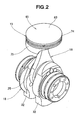
- the connecting rod 16 is coupled swingably to the piston 13 at one end and to the crankshaft 18 at the other end, as shown in FIG. 2.
- the piston 13 may, for example, be obtained by casting a material designated as AC8A [JIS H 5202], subjecting its casting to T6 heat treatment and machine finishing it.
- the connecting rod 16 is preferably formed from chromium or chromium-molybdenum steel, or a titanium alloy.
- FIG. 3 is an exploded perspective view showing the coupling structure for the piston and connecting rod according to this invention.
- the coupling structure has a protrusion formed on the rear surface of the crown 65 of a piston 13 and having a semi-spherical concavity (as will be described in detail later), a spherical small end 66 formed on one end of a connecting rod 16, a split holder 68 having a spherical inner surface 67 for supporting a lower portion of the small end 66 and a threaded fixing ring for securing the holder 68 to the rear surface of the crown 65 of the piston 13, as shown in FIG. 3.
- reference numeral 69 denotes the spherical surface of the small end 66.
- the connecting rod 16 is formed by the small end 66, an annular big end 25 and a rod body 73 to which the small and big ends 66 and 25 are joined integrally.
- the holder 68 is formed by two holder halves 68a. 68b denotes the mating surfaces where the two holder halves 68a are mated.
- the piston 13 is a one-piece structure and has the crown 65 shaped like a disk, a tubular land 74 extending downward from the edge of the crown 65 and having a large wall thickness, tubular skirts 75 extending downward from the land 74 and having a smaller thickness than that of the land 74, a cup-shaped support (protrusion) 78 protruding from the rear surface 77 of the crown 65 to form a semi-spherical concavity 76 in which the small end 66 of the connecting rod 16 is slidably fitted and a plurality of ribs 81 extending radially between the land 74 and the cup-shaped support 78 and downward from the rear surface 77 of the crown 65, as shown in FIG. 4.
- the crown 65 has a crown surface 83 defining a part of the combustion chamber 37 (see FIG. 1).
- the land 74 has a top land 74a, a top ring groove 74b, a second land 74c, a second ring groove 74d, a third land 74e and an oil ring groove 74f formed on its outer peripheral surface in the order mentioned as viewed from the crown surface 83 to the skirts 25, and a top ring, a second ring and an oil ring which are not shown are fitted in the grooves 74b, 74d and 74f, respectively.
- the cup-shaped support 78 has a downwardly opening concavity 91, the semi-spherical concavity 76 formed in the bottom 92 of the concavity 91 and a female thread 94 formed in the cylindrical inner surface 93 of the concavity 91.
- the connecting rod 16 is swingably coupled to the piston 13 by having its spherical small end 66 held against the wall of the semi-spherical concavity 76, placing the holder 68 in the downwardly opening concavity 91 to have the small end 66 of the connecting rod 16 held on the spherical inner surfaces 67 of the holder 68 and engaging a male thread 95 formed on cylindrical outer surface 111 (FIG.
- the cylindrical outer surface 111 of the fixing ring 71 having the male thread 95 defines a threaded portion of the fixing ring 71 and the cylindrical inner surface 93 of the cup-shaped support (protrusion) 78 having the female thread 94 defines a threaded portion of the cup-shaped support (protrusion) 78.
- the threaded portions 111 and 93 are concentric to the semi-spherical concavity 76.
- the cup-shaped support 78 having the semi-spherical concavity 76 and the threaded portion 93, the spherical small end 66, the holder 68 having the spherical inner surface 67 and the threaded fixing ring 71 form the spherical joint 14.
- the holder 68 is held against rotation about the cup-shaped support 78 by a stop pin not shown, and has a rotation preventing surface not shown, but abutting on the rod body 73 to hold the piston 13 against rotation about the connecting rod 16.
- Each holder half 68a has a shoulder 68c around its outer surface and the fixing ring 71 has its end (upper end in FIG. 4) held against the shoulder 68c to fix the holder half 68a to the cup-shaped support 78.
- the fixing ring 71 has around its outer peripheral surface the male thread 95 and a plurality of engaging recesses 71a in which a tool is engageable to turn the fixing ring 71.
- the connecting rod 16 has hollows 96 to 100 in its big end 25 and rod body 73 and a hollow 101 in its small end 66 to have its weight reduced and also has oil holes 103 to 105 through which oil can be supplied from a mounting hole 102 formed in its big end 25 to the sliding surfaces of the spherical joint 14.
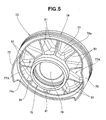
- the ribs 81 are formed on the rear surface 77 of the crown 65 (see FIG. 4) of the piston 13 for connecting the land 74 and the cup-shaped support 78, as shown in FIG. 5.
- Reference numeral 77A denotes a jib holding recess defined by the rear surface 77, every two adjoining ribs 81, the inner surface 74a of the land 74 and the outer surface 78a of the cup-shaped support 78 for holding a jig (which will be described later) when coupling the piston 13 and the connecting rod 16.
- the ribs 81 provide a rigid connection between the land 74 and the cup-shaped support 78 and thereby raise the rigidity of the upper portion of the piston 13.
- the individual ribs 81 may be small enough in thickness to suppress any undesirable increase in weight that they would otherwise give to the piston.
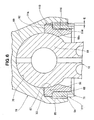
- the holder 68 is fixed to the cup-shaped support 78 when the female thread 94 formed on the inner surface 93 of the downwardly opening concavity 91 of the cup-shaped support 78 and the made thread 95 formed on the outer surface 111 of the fixing ring 71 are engaged with each other after the holder 68 is inserted into the concavity 91 to hold the small end 66 of the connecting rod 16.
- Clearances 113 and 114 are formed between the inner surface 93 of the cup-shaped support 78 and the outer surface of the holder 68 and between the inner surface 116 of the fixing ring 71 and the outer surface of the holder 68, respectively, so that the holder 68 may contact only the bottom 92 of the downward concavity 91 and the spherical surface 69 of the small end 66 and hold the spherical surface 69 of the small end 66 accurately on the spherical inner surface defined by the semi-spherical concavity 76 and the spherical surfaces 67 irrespective of, for example, the machining accuracy of the inner peripheral surface 93 of the downward concavity 91 or the inner surface 116 of the fixing ring 71.
- the spherical small end 66 of the connecting rod 16 is inserted into the downwardly opening concavity 91 and semi-spherical concavity 76 of the cup-shaped support 78, as shown in FIGS. 7A and 7B.
- the split holder 68 is inserted into the downward concavity 91 as shown by arrows in FIG. 8A.
- the holder 68 is brought into contact with the bottom 92 of the downward concavity 91, the male thread 95 of the fixing ring 71 is engaged with the female thread 94 of the cup-shaped support 78 and the end 71b of the fixing ring 71 is pressed against the shoulder 68c of the holder 68, as shown in FIG. 8B.
- a tool is engaged in the engaging recesses 71a of the fixing ring 71 to turn the fixing ring 71 and thereby secure the holder 68 to the cup-shaped support 78.
- the coupling of the piston 13 and the connecting rod 16 is finished.
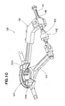
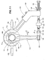
- a tightening jig 120 includes a piston holding portion 121 for holding the piston 13 in position, a supporting portion 122 supporting the piston holding portion 121 slidably, a tightening force generating portion 123 having one end connected with the supporting portion 122 for generating a tightening force for tightening the fixing ring 71 (see FIG. 4) and an arm-shaped wrench portion 124 connected to another end of the tightening force generating portion 123 and engaged about the fixing ring 71.
- the piston holding portion 121 has a plurality of projections (FIG. 10) fitted in the jig holding recesses 77A formed on the rear surface 77 of the piston 13 as described with reference to FIG. 5 to hold the piston 13 against rotation, as shown in FIG. 9.
- the piston holding portion 121 also has a pair of handles 126 for securing the piston 13 and the tightening jig 120 together.
- the piston holding portion 121 is connected to the supporting portion 122 by a straight portion 127.
- the supporting portion 122 has a guide portion 132 having a rectangular bore 131 into which the straight portion 127 extends, and a U-shaped portion 133 formed integrally with the guide portion 132.
- the straight portion 127 is secured to the guide portion 132 by bolts 135.
- the tightening force generating portion 123 includes a block 138 attached to the U-shaped portion 133 rotatably by a first pin 137, a first bolt 141 extending through the block 138, a load cell 142 connected threadedly with the end of the first bolt 141, a connecting member 143 connected threadedly with the load cell 142 and an end member 146 connected to the connecting member 143 by a second pin 144, while the wrench portion 124 has its end attached to the end member 146.
- the load cell 142 is a sensor for detecting the tightening force for the fixing ring 71 and controls the tightened state of the fixing ring 71 by a tightening torque calculated by multiplying the detected tightening force by the arm length of the wrench portion 124.
- the piston holding portion 121 is slidable by the supporting portion 122 so that the tightening force generating portion 123 and the wrench portion 124 may lie at right angles to each other to permit an accurate calculation of the tightening torque.
- Reference numeral 148 denotes an adjust nut which can be turned about the first bolt 141 to adjust its axial position
- 151 denotes a washer
- 152 denotes a first lock nut for holding the load cell 142 against rotation
- 153 denotes a second lock nut for holding the connecting member 143 against rotation
- 154 denotes a second bolt for attaching the end of the wrench portion 124 to the end member 146.
- FIG. 10 shows the projections 121A formed on the piston holding portion 121 of the tightening jig 120 for fitting in the jig holding recesses 77A (see FIG.
- the small end 66 of the connecting rod 16 and then the holder 68 are attached to the piston 13 and the fixing ring 71 is preliminarily tightened in the bottom of the piston 13, or more particularly its cup-shaped support 78 (see FIG. 4).
- the tightening jig 120 is secured to the piston 13 and a plurality of engaging pawls 158 formed in a C-shaped engaging portion 157 at the free end of the wrench portion 124 are engaged in the engaging recesses 71a of the fixing ring 71.
- the adjust nut 148 is turned about the first bolt 141 as shown by, for example, an outline arrow A.
- This causes the tightening force generating portion 123 as a whole to move axially as shown by an arrow B.
- the wrench portion 124 is rotated in the direction of an outline arrow D to turn the fixing ring 71 about the piston 13.
- the fixing ring 71 can be fully tightened by an adequate tightening torque.
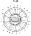
- the connecting rod 16 has flat sliding surfaces 73b formed on its sides, or more specifically on opposite sides 73a of the base of its small end 66 (see FIG. 4) or of the rod portion 73 of its small end 66 in parallel to the swinging direction of the connecting rod 16 (horizontal as viewed in the drawing) as shown in FIG. 12.
- the holder 68 (which is shown by a thick line for a clearer showing of its shape) has guide surfaces 68e formed along opposite edges of a rectangular opening 68d formed therein to have the connecting rod 16 extend therethrough, and making sliding contact with the sliding surfaces 73b for guiding the rod portion 73 in its swinging motion.
- the land 74 has its inner surface shown at 74a and the cup-shaped support 78 has its outer surface shown at 78a.
- the sliding surfaces 73b formed on the connecting rod 16 in parallel to its swinging direction and the guide surfaces 68e formed on the holder 68 for guiding the sliding surfaces 73b make it possible to prevent the rotation of the piston 13 about the connecting rod 16 and therefore about the axis of the cylinder.
- FIG. 13 shows by cross hatching for better clarity one of the flat guide surfaces 68e formed on the holder halves 68a, respectively, of the holder 68.
- each sliding surface 73b of the connecting rod 16 is a substantially arcuate area having one side extending along an arcuate boundary line 16a defined between the small end 66 and the side 73a of the rod body 73, as shown by cross hatching for better clarity.
- Each guide surface 68e of the holder 68 is an area having an arcuate side 68f defined by the edge of its spherical surface 67, a straight side 68g opposite the side 68f and a pair of slanting sides 68h and 68j, as shown by dots for better clarity.
- 110 denotes an area in which the guide surface 68e of the holder 68 and the sliding surface 73b of the connecting rod 16 overlap each other as viewed in side elevation, or an area of contact therebetween.
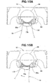
- FIG. 15A shows the connecting rod 16 not inclined to the axis of the cylinder, i.e. when the piston 13 stays at the top or bottom dead center of the cylinder.
- the overlapping area 110 between the guide surface 68e of the holder 68 and the sliding surface 73b of the connecting rod 16 is shown by hatching.
- FIG. 15B shows the connecting rod 16 inclined as a result of, for example, the movement of the piston 13 from the top to bottom dead center of the cylinder.
- the sliding surface 73b of the connecting rod 16 swings as shown by an arrow in sliding contact with the guide surface 68e of the holder 68 to have the holder 68 hold the piston 13 against rotation.
- the sliding surfaces 73b of the connecting rod 16 as guided by the guide surfaces 68e of the holder 68 make it possible to prevent the rotation of the piston 13 about the axis of the cylinder.
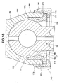
- FIG. 16 is a sectional view showing a joint structure according to another embodiment of this invention.
- a spherical joint 160 forming the joint structure has a cup-shaped support 161 protruding from the crown of a piston, a spherical small end 66 of a connecting rod 16 fitted slidably in a semi-spherical concavity 76 formed in the cup-shaped support 161, a holder 162 holding the small end 66 and a threaded fixing ring 163 securing the holder 162 to the cup-shaped support 161, as shown in FIG. 16.
- the cup-shaped support 161 has a downwardly opening concavity 165 formed inwardly of its lower end and a male thread 167 formed on its outer peripheral surface 166 adjacent to its lower end.
- a semi-spherical concavity 76 as described before is formed in the bottom 165a of the downward concavity 165.
- the outer peripheral surface 166 having the male thread 167 defines a threaded portion of the cup-shaped support (protrusion) 161.
- the holder 162 has a spherical inner surface 171 holding the small end 66 and a flange 173 formed at one end (or its lower end as shown) and contacting the end of the cup-shaped support 161.
- the fixing ring 163 has a female thread 176 formed on its inner surface 175 and engaging with the male thread 167 of the cup-shaped support 161, a flange 177 formed at its end (or its lower end as shown) and holding the flange 173 of the holder 162 against the end of the cup-shaped support 161 and a plurality of engaging recesses 181 formed in its outer surface 178 for turning the fixing ring 163.
- the inner surface 175 having the female thread 176 defines a threaded portion of the fixing ring 163.
- the fixing ring 163 having the female thread 176 formed on its inner surface 175 and the engaging recesses 181 formed in its outer surface 178 as described can be turned easily by a tool engaged in its engaging recesses 181 to achieve an improved efficiency in a fixing job. Moreover, the engaging recesses 181 can be formed in the outer surface 178 of the fixing ring 163 easily to improve its workability.
- FIG. 14 shows the sliding surface 73b of the connecting rod 16 as being substantially arcuate in shape, it may alternatively be rectangular, V-shaped or inverted triangular.
- a coupling structure for coupling a piston (13) and a connecting rod (16) has a protrusion (78) formed on a rear surface of a crown of the piston and having a semi-spherical concavity (91) and a threaded portion (93) concentric to the concavity, a substantially spherical small end (66) formed at one end of the connecting rod, a holder (68) holding the spherical small end of the connecting rod slidably in the semi-spherical concavity of the protrusion and a fixing ring (71) having a threaded portion (111) engaging with the threaded portion of the protrusion for securing the holder to the protrusion of the piston.
Abstract
Description
- This invention relates to an improvement in the spherical coupling structure between a piston and a connecting rod.
- There is known a coupling structure between a piston and a connecting rod using a spherical joint as disclosed in, for example, JP-UM-A-3-17369, JP-A-9-144879, JP-A-2000-337506 and JP-A-2000-213646.
- The coupling structure disclosed in JP-UM-A-3-17369 has a
semi-spherical concavity 201 formed in the rear surface of the crown of apiston 200, asmall end 203 formed on a connectingrod 202 in a substantially spherical shape conforming to the shape of theconcavity 201 and twosplit flanges 204 screwed to the crown surface extending around theconcavity 201 of thepiston 200 for holding against thepiston 200 thesmall end 203 of the connectingrod 202 fitted slidably in theconcavity 201, as shown in FIG. 17 hereof. - The coupling structure as described requires for securing the
flanges 204 to thepiston 200 sixscrews 206 which add to the number of parts for the structure, its cost and its weight correspondingly. As the number of thescrews 206 which are used is large, a correspondingly large amount of time and labor is required for coupling the piston to the connecting rod and thereby brings about a lowering of productivity. - FIG. 18 hereof shows the spherical coupling structure between a piston and a connecting rod as disclosed in JP-A-9-144879. The coupling structure includes a concave
spherical washer 212 fitted in a concavity formed in the rear surface of thecrown 211 of apiston 210, though not designated, asmall end 216 formed on a connectingrod 214 in a spherical shape conforming to a concavespherical surface 213 formed in the concavespherical washer 212, aholder 217 for holding thesmall end 216 slidably in the concavespherical washer 212, a rotation- preventingmember 218 held on theholder 217 and a plurality of pairs ofbolts 221 andnuts 222 for securing the concavespherical washer 212,holder 217 and rotation-preventingmember 218 together to thepiston 210. - The coupling structure as described includes the concave
spherical washer 212,holder 217, rotation-preventingmember 218 and pairs ofbolts 221 andnuts 222 which increase the number of parts for the structure and its weight. The concavespherical washer 212 is, among others, responsible for the increased weight, since it is made of an iron-based material. The increased number of parts as stated requires an increased amount of time and labor for coupling the piston to the connecting rod and thereby brings about a lowering of productivity, as in the case of the coupling structure disclosed in JP-UM-A-3-17369 (FIG. 17). - The coupling structure disclosed in JP-A-2000-337506 includes a
small end 235 formed on a connectingrod 234 in a substantially cross shape having a spherical surface, as shown in FIG. 19A. The substantially cross-shapedsmall end 235 has afirst protrusion 236 and asecond protrusion 237 crossing each other at right angles, thesecond protrusion 237 being smaller in diameter than thefirst protrusion 236.Apiston 230 has a concavity 241 (FIG. 19B) formed in the rear surface of acrown 231 and having a spherical inner wall surface. Theconcavity 241 has at its open end across-shaped opening 242 conforming to the shape of thesmall end 235 of the connectingrod 234. For assembly, theprotrusion 237 of the connectingrod 234 is inserted into theconcavity 241 of thepiston 230 through itscross-shaped opening 242 and turned by 90 degrees, whereby thepiston 230 and the connectingrod 234 are coupled together. - The coupling structure as described makes it possible to reduce the number of parts and the amount of time and labor as required for assembly, since it does not require any of the screws, bolts or other fasteners as shown in FIGS. 17 and 18. However, the opening 242 of the
concavity 241 of thepiston 230 and thesmall end 235 of the connectingrod 234, which are both cross-shaped, require a complicated machining job and need to be improved from the standpoints of productivity and production cost. The cross-shapedsmall end 235 of the connectingrod 234 has a relatively small area of contact with the wall of theconcavity 241 of thepiston 230, which increases the pressure acting upon the joint and thereby lowers its coupling strength. - FIG. 20 hereof shows the spherical coupling structure between a piston and a connecting rod as disclosed in JP-A-2000-213646. The coupling structure has a
semi-spherical concavity 251 formed in the rear surface of the crown of apiston 250, afixing plate 252 secured to the rear surface of the crown of thepiston 250 and a sphericalsmall end 256 of a connectingrod 254 held slidably in a spherical space defined by theconcavity 251 of thepiston 250 and a sphericalinner surface 253 of thefixing plate 252. Thesmall end 256 of the connectingrod 254 has its center C (i.e. the center of the joint between thepiston 250 and the connecting rod 254) offset radially of thepiston 250 by an amount δ of eccentricity from its axial centerline CL. - The offsetting of the center C of the joint between the
piston 250 and the connectingrod 254 by δ from the axial centerline of thepiston 250 prevents thepiston 250 from rotating about the center C of its joint with the connectingrod 254 by causing thepiston 250 to contact the wall surface of a cylinder. When thepiston 250 and the cylinder has a large clearance therebetween during, for example, the beginning of engine operation when thepiston 250 is still at a low temperature, however, thepiston 250 rotates about the connectingrod 254 and if thepiston 250 contacts the cylinder in any portion of high rigidity other than its skirts, thepiston 250 gives the cylinder a large striking force which is likely to deprive the clearance between thepiston 250 and the cylinder of a lubricant oil film. It is, therefore, desirable to be able to prevent the rotation of thepiston 250 about the connectingrod 254 irrespective of the stage of engine operation. It is also desirable to prevent the rotation of thepiston 250 without incurring any additional cost. - Therefore, it is desirable to provide a spherical coupling structure between a piston and a connecting rod which requires only a small number of parts, is thus inexpensive and small in weight and thereby improves productivity, and which makes it possible to prevent the rotation of the piston about the connecting rod irrespective of the stage of operation of an internal combustion engine and without incurring any additional cost.
- According to this invention, there is provided a coupling structure for coupling a piston and a connecting rod, including a protrusion formed on the rear surface of the crown of the piston and having a semi-spherical concavity and a threaded portion concentric to the concavity, a substantially spherical small end formed at one end of the connecting rod, a holder having a spherical inner surface and holding the substantially spherical small end of the connecting rod slidably in a substantially spherical space defined by its inner surface and the semi-spherical concavity of the protrusion and a fixing ring having a threaded portion engaging with the threaded portion of the protrusion for securing the holder to the protrusion of the piston.
- The coupling structure for a piston and a connecting rod as set forth above relies upon only the engagement of a pair of threaded portions for coupling a piston and a connecting rod easily and reliably, and requires a fewer parts and is thus less expensive and smaller in weight than any known structure employing a plurality of bolts. The fewer parts make it possible to facilitate the coupling of the connecting rod to the piston and thereby improve the productivity of the engine and cut down its cost of manufacture.
- According to an aspect of this invention, the threaded portion of the protrusion is defined by a cylindrical inner surface thereof extending from the open edge of the semi-spherical concavity and having a female thread, while the threaded portion of the fixing ring is defined by a cylindrical outer surface thereof and having a male thread. The threaded joint formed by the female and male threads has so short a distance from the area where the fixing member holds the supporting member in position, that the fixing member has only a small bending stress.
- According to another aspect of this invention, the threaded portion of the protrusion is defined by a cylindrical outer surface thereof having a male thread, while the threaded portion of the fixing ring is defined by a cylindrical inner surface thereof having a female thread. The fixing ring may have an engaging recess formed in its outer surface for engaging a part of a jig for turning the ring.
- The coupling structure for a piston and a connecting rod according to this invention may further include a sliding surface formed near the base of the spherical small end of the connecting rod in parallel to the swinging direction of the connecting rod and a guide surface formed on the holder in sliding contact with the sliding surface of the connecting rod for guiding its swinging motion, the sliding and guide surfaces defining a device for preventing the rotation of the piston about the connecting rod and thereby the longitudinal axis of a cylinder.
- According to the spherical coupling structure for a piston and a connecting rod as described above, the guiding of the sliding surface of the connecting rod by the guide surface of the holder ensures that the rotation of the piston be prevented irrespective of the stage of operation of an internal combustion engine, as during the beginning of its operation when the piston and cylinder are still at a low temperature. As the sliding surface of the connecting rod and the guide surface of the holder prevent the rotation of the piston, no additional device is required for that purpose, but the structure according to this invention has only a few parts and is, therefore, inexpensive.
- Certain preferred embodiments of the present invention will be described in detail below, by way of example only, with reference to the accompanying drawings, in which:
- FIG. 1 is a longitudinal sectional view of an internal combustion engine including a piston and a connecting rod having a coupling structure according to this invention;
- FIG. 2 is a perspective view of the piston, connecting rod and a crankshaft as put together;
- FIG. 3 is an exploded perspective view of the coupling structure for the piston and connecting rod according to this invention;
- FIG. 4 is a longitudinal sectional view of the piston and connecting rod having the coupling structure according to this invention;
- FIG. 5 is a perspective view of the piston showing its rear surface;
- FIG. 6 is an enlarged sectional view of the joint for the piston and connecting rod according to this invention;
- FIGS. 7A and 7B are sectional views showing the step of fitting the spherical small end of the connecting rod in the semi- spherical concavity of the piston to constitute the coupling of the piston and connecting rod according to this invention;
- FIGS. 8A and 8B are sectional views showing the step of having the small end of the connecting rod held by a holder and securing the holder to the piston by a fixing ring;
- FIG. 9 is a perspective view showing a jig for tightening the fixing ring according to this invention;
- FIG. 10 is a perspective view of the tightening jig as viewed from a different angle from FIG. 9;
- FIG. 11 is a top plan view of the tightening jig showing its operation;
- FIG. 12 is a bottom plan view, partly in section, of the piston and connecting rod according to this invention;
- FIG. 13 is an exploded perspective view of the holder according to this invention;
- FIG. 14 is a side elevational view showing the relation between the connecting rod and holder according to this invention;
- FIGS. 15A and 15B are schematic views explaining the performance of the device for preventing the rotation of the piston according to this invention;
- FIG. 16 is an enlarged sectional view showing a joint structure for a piston and a connecting rod according to another embodiment of this invention;
- FIG. 17 is a sectional view showing a known coupling structure for a piston and a connecting rod including flanges for holding them together;
- FIG. 18 is a sectional view showing another known coupling structure for a piston and a connecting rod including a retainer for holding them together;
- FIG. 19A is an exploded perspective view showing still another known coupling structure for a piston and a connecting rod;
- FIG. 19B is a bottom plan view showing the rear surface of the crown of the piston; and
- FIG. 20 is a sectional view showing still another known coupling structure for a piston and a connecting rod including a fixing plate for holding them together.
-
- Referring first to FIG. 1, an
internal combustion engine 10 has acylinder block 11, apiston 13 fitted movably in a cylinder bore 12 formed in thecylinder block 11, a connectingrod 16 coupled to thepiston 13 by a spherical joint 14, and acrankshaft 18 attached rotatably to a lower portion of thecylinder block 11 and supporting the connectingrod 16 swingably by ahollow crank pin 17. - The
cylinder block 11 has acylinder 21 formed in its upper portion, acylindrical sleeve 22 fitted in thecylinder 21 and defining the cylinder bore 12 and anupper crankcase 23 attached to the bottom of thecylinder 21. -
Reference numeral 31 denotes a sliding bearing disposed between thebig end 25 of the connectingrod 16 and thecrank pin 17; 32, a counterweight on thecrankshaft 18; 33, a cylinder head attached to the top of thecylinder block 11 with a head gasket disposed therebetween, but not shown; 34, an intake valve; 36, an exhaust valve; 37, a combustion chamber; 38, a lower crankcase secured to the bottom of theupper crankcase 23 bybolts 41 and forming a crankcase therewith; and 42, an oil pan secured to the bottom of thelower crankcase 38 bybolts 44. - The connecting
rod 16 is coupled swingably to thepiston 13 at one end and to thecrankshaft 18 at the other end, as shown in FIG. 2. Thepiston 13 may, for example, be obtained by casting a material designated as AC8A [JIS H 5202], subjecting its casting to T6 heat treatment and machine finishing it. The connectingrod 16 is preferably formed from chromium or chromium-molybdenum steel, or a titanium alloy. - FIG. 3 is an exploded perspective view showing the coupling structure for the piston and connecting rod according to this invention. The coupling structure has a protrusion formed on the rear surface of the
crown 65 of apiston 13 and having a semi-spherical concavity (as will be described in detail later), a sphericalsmall end 66 formed on one end of a connectingrod 16, asplit holder 68 having a sphericalinner surface 67 for supporting a lower portion of thesmall end 66 and a threaded fixing ring for securing theholder 68 to the rear surface of thecrown 65 of thepiston 13, as shown in FIG. 3. In FIG. 3,reference numeral 69 denotes the spherical surface of thesmall end 66. The connectingrod 16 is formed by thesmall end 66, an annularbig end 25 and arod body 73 to which the small andbig ends holder 68 is formed by twoholder halves 68a. 68b denotes the mating surfaces where the twoholder halves 68a are mated. - The
piston 13 is a one-piece structure and has thecrown 65 shaped like a disk, atubular land 74 extending downward from the edge of thecrown 65 and having a large wall thickness,tubular skirts 75 extending downward from theland 74 and having a smaller thickness than that of theland 74, a cup-shaped support (protrusion) 78 protruding from therear surface 77 of thecrown 65 to form asemi-spherical concavity 76 in which thesmall end 66 of the connectingrod 16 is slidably fitted and a plurality ofribs 81 extending radially between theland 74 and the cup-shapedsupport 78 and downward from therear surface 77 of thecrown 65, as shown in FIG. 4. Thecrown 65 has acrown surface 83 defining a part of the combustion chamber 37 (see FIG. 1). - The
land 74 has atop land 74a, atop ring groove 74b, asecond land 74c, asecond ring groove 74d, athird land 74e and anoil ring groove 74f formed on its outer peripheral surface in the order mentioned as viewed from thecrown surface 83 to theskirts 25, and a top ring, a second ring and an oil ring which are not shown are fitted in thegrooves - The cup-shaped
support 78 has a downwardly openingconcavity 91, thesemi-spherical concavity 76 formed in the bottom 92 of theconcavity 91 and afemale thread 94 formed in the cylindricalinner surface 93 of theconcavity 91. The connectingrod 16 is swingably coupled to thepiston 13 by having its sphericalsmall end 66 held against the wall of thesemi-spherical concavity 76, placing theholder 68 in the downwardly openingconcavity 91 to have thesmall end 66 of the connectingrod 16 held on the sphericalinner surfaces 67 of theholder 68 and engaging amale thread 95 formed on cylindrical outer surface 111 (FIG. 6) of the fixingring 71 with thefemale thread 94 formed on the cylindricalinner surface 93 of the cup-shapedsupport 78 to secure the fixingring 71 to the cup-shaped support (protrusion) 78. The cylindrical outer surface 111 of the fixingring 71 having themale thread 95 defines a threaded portion of the fixingring 71 and the cylindricalinner surface 93 of the cup-shaped support (protrusion) 78 having thefemale thread 94 defines a threaded portion of the cup-shaped support (protrusion) 78. The threadedportions 111 and 93 are concentric to thesemi-spherical concavity 76. - The cup-shaped
support 78 having thesemi-spherical concavity 76 and the threadedportion 93, the sphericalsmall end 66, theholder 68 having the sphericalinner surface 67 and the threaded fixingring 71 form the spherical joint 14. - The
holder 68 is held against rotation about the cup-shapedsupport 78 by a stop pin not shown, and has a rotation preventing surface not shown, but abutting on therod body 73 to hold thepiston 13 against rotation about the connectingrod 16. Eachholder half 68a has ashoulder 68c around its outer surface and the fixingring 71 has its end (upper end in FIG. 4) held against theshoulder 68c to fix theholder half 68a to the cup-shapedsupport 78. - The fixing
ring 71 has around its outer peripheral surface themale thread 95 and a plurality of engagingrecesses 71a in which a tool is engageable to turn the fixingring 71. - The connecting
rod 16 hashollows 96 to 100 in itsbig end 25 androd body 73 and a hollow 101 in itssmall end 66 to have its weight reduced and also hasoil holes 103 to 105 through which oil can be supplied from a mountinghole 102 formed in itsbig end 25 to the sliding surfaces of the spherical joint 14. - The
ribs 81 are formed on therear surface 77 of the crown 65 (see FIG. 4) of thepiston 13 for connecting theland 74 and the cup-shapedsupport 78, as shown in FIG. 5.Reference numeral 77A denotes a jib holding recess defined by therear surface 77, every two adjoiningribs 81, theinner surface 74a of theland 74 and theouter surface 78a of the cup-shapedsupport 78 for holding a jig (which will be described later) when coupling thepiston 13 and the connectingrod 16. - The
ribs 81 provide a rigid connection between theland 74 and the cup-shapedsupport 78 and thereby raise the rigidity of the upper portion of thepiston 13. Theindividual ribs 81 may be small enough in thickness to suppress any undesirable increase in weight that they would otherwise give to the piston. - Referring to FIG. 6, it is noted that the
holder 68 is fixed to the cup-shapedsupport 78 when thefemale thread 94 formed on theinner surface 93 of the downwardly openingconcavity 91 of the cup-shapedsupport 78 and the madethread 95 formed on the outer surface 111 of the fixingring 71 are engaged with each other after theholder 68 is inserted into theconcavity 91 to hold thesmall end 66 of the connectingrod 16. -
Clearances inner surface 93 of the cup-shapedsupport 78 and the outer surface of theholder 68 and between theinner surface 116 of the fixingring 71 and the outer surface of theholder 68, respectively, so that theholder 68 may contact only the bottom 92 of thedownward concavity 91 and thespherical surface 69 of thesmall end 66 and hold thespherical surface 69 of thesmall end 66 accurately on the spherical inner surface defined by thesemi-spherical concavity 76 and thespherical surfaces 67 irrespective of, for example, the machining accuracy of the innerperipheral surface 93 of thedownward concavity 91 or theinner surface 116 of the fixingring 71. - A method of coupling the
piston 13 and the connectingrod 16 will now be described with reference to FIGS. 7A, 7B, 8A and 8B. - The spherical
small end 66 of the connectingrod 16 is inserted into the downwardly openingconcavity 91 andsemi-spherical concavity 76 of the cup-shapedsupport 78, as shown in FIGS. 7A and 7B. - After the
spherical surface 69 of the connectingrod 16 is fitted in thesemi-spherical concavity 76, thesplit holder 68 is inserted into thedownward concavity 91 as shown by arrows in FIG. 8A. - Then, the
holder 68 is brought into contact with the bottom 92 of thedownward concavity 91, themale thread 95 of the fixingring 71 is engaged with thefemale thread 94 of the cup-shapedsupport 78 and theend 71b of the fixingring 71 is pressed against theshoulder 68c of theholder 68, as shown in FIG. 8B. A tool is engaged in the engagingrecesses 71a of the fixingring 71 to turn the fixingring 71 and thereby secure theholder 68 to the cup-shapedsupport 78. Thus, the coupling of thepiston 13 and the connectingrod 16 is finished. - Referring to FIG. 9, a tightening
jig 120 includes apiston holding portion 121 for holding thepiston 13 in position, a supportingportion 122 supporting thepiston holding portion 121 slidably, a tighteningforce generating portion 123 having one end connected with the supportingportion 122 for generating a tightening force for tightening the fixing ring 71 (see FIG. 4) and an arm-shapedwrench portion 124 connected to another end of the tighteningforce generating portion 123 and engaged about the fixingring 71. - The
piston holding portion 121 has a plurality of projections (FIG. 10) fitted in thejig holding recesses 77A formed on therear surface 77 of thepiston 13 as described with reference to FIG. 5 to hold thepiston 13 against rotation, as shown in FIG. 9. - The
piston holding portion 121 also has a pair ofhandles 126 for securing thepiston 13 and the tighteningjig 120 together. Thepiston holding portion 121 is connected to the supportingportion 122 by astraight portion 127. - The supporting
portion 122 has aguide portion 132 having arectangular bore 131 into which thestraight portion 127 extends, and aU-shaped portion 133 formed integrally with theguide portion 132. Thestraight portion 127 is secured to theguide portion 132 bybolts 135. - The tightening
force generating portion 123 includes ablock 138 attached to theU-shaped portion 133 rotatably by afirst pin 137, afirst bolt 141 extending through theblock 138, aload cell 142 connected threadedly with the end of thefirst bolt 141, a connectingmember 143 connected threadedly with theload cell 142 and anend member 146 connected to the connectingmember 143 by asecond pin 144, while thewrench portion 124 has its end attached to theend member 146. - The
load cell 142 is a sensor for detecting the tightening force for the fixingring 71 and controls the tightened state of the fixingring 71 by a tightening torque calculated by multiplying the detected tightening force by the arm length of thewrench portion 124. Thepiston holding portion 121 is slidable by the supportingportion 122 so that the tighteningforce generating portion 123 and thewrench portion 124 may lie at right angles to each other to permit an accurate calculation of the tightening torque. -
Reference numeral 148 denotes an adjust nut which can be turned about thefirst bolt 141 to adjust its axial position, 151 denotes a washer, 152 denotes a first lock nut for holding theload cell 142 against rotation, 153 denotes a second lock nut for holding the connectingmember 143 against rotation and 154 denotes a second bolt for attaching the end of thewrench portion 124 to theend member 146. - FIG. 10 shows the
projections 121A formed on thepiston holding portion 121 of the tighteningjig 120 for fitting in thejig holding recesses 77A (see FIG. - 5) formed on the rear surface of the piston 13 (see FIG. 9).
-
- Description will now be made of the performance of the tightening
jig 120. - Referring first to FIG. 3 again, the
small end 66 of the connectingrod 16 and then theholder 68 are attached to thepiston 13 and the fixingring 71 is preliminarily tightened in the bottom of thepiston 13, or more particularly its cup-shaped support 78 (see FIG. 4). - Referring now to FIG. 11, the tightening
jig 120 is secured to thepiston 13 and a plurality of engagingpawls 158 formed in a C-shapedengaging portion 157 at the free end of thewrench portion 124 are engaged in the engagingrecesses 71a of the fixingring 71. - Then, the adjust
nut 148 is turned about thefirst bolt 141 as shown by, for example, an outline arrow A. This causes the tighteningforce generating portion 123 as a whole to move axially as shown by an arrow B. As a result, thewrench portion 124 is rotated in the direction of an outline arrow D to turn the fixingring 71 about thepiston 13. Thus, the fixingring 71 can be fully tightened by an adequate tightening torque. - The connecting
rod 16 has flat slidingsurfaces 73b formed on its sides, or more specifically onopposite sides 73a of the base of its small end 66 (see FIG. 4) or of therod portion 73 of itssmall end 66 in parallel to the swinging direction of the connecting rod 16 (horizontal as viewed in the drawing) as shown in FIG. 12. On the other hand, the holder 68 (which is shown by a thick line for a clearer showing of its shape) hasguide surfaces 68e formed along opposite edges of arectangular opening 68d formed therein to have the connectingrod 16 extend therethrough, and making sliding contact with the slidingsurfaces 73b for guiding therod portion 73 in its swinging motion. Theland 74 has its inner surface shown at 74a and the cup-shapedsupport 78 has its outer surface shown at 78a. - The sliding
surfaces 73b formed on the connectingrod 16 in parallel to its swinging direction and theguide surfaces 68e formed on theholder 68 for guiding the slidingsurfaces 73b make it possible to prevent the rotation of thepiston 13 about the connectingrod 16 and therefore about the axis of the cylinder. - FIG. 13 shows by cross hatching for better clarity one of the
flat guide surfaces 68e formed on theholder halves 68a, respectively, of theholder 68. - Referring to FIG. 14, each sliding
surface 73b of the connectingrod 16 is a substantially arcuate area having one side extending along anarcuate boundary line 16a defined between thesmall end 66 and theside 73a of therod body 73, as shown by cross hatching for better clarity. Eachguide surface 68e of theholder 68 is an area having anarcuate side 68f defined by the edge of itsspherical surface 67, astraight side 68g opposite theside 68f and a pair of slantingsides guide surface 68e of theholder 68 and the slidingsurface 73b of the connectingrod 16 overlap each other as viewed in side elevation, or an area of contact therebetween. - Description will now be made of the performance of the mechanism for preventing the rotation of the piston.
- FIG. 15A shows the connecting
rod 16 not inclined to the axis of the cylinder, i.e. when thepiston 13 stays at the top or bottom dead center of the cylinder. The overlappingarea 110 between theguide surface 68e of theholder 68 and the slidingsurface 73b of the connectingrod 16 is shown by hatching. - FIG. 15B shows the connecting
rod 16 inclined as a result of, for example, the movement of thepiston 13 from the top to bottom dead center of the cylinder. The slidingsurface 73b of the connectingrod 16 swings as shown by an arrow in sliding contact with theguide surface 68e of theholder 68 to have theholder 68 hold thepiston 13 against rotation. Thus, the slidingsurfaces 73b of the connectingrod 16 as guided by the guide surfaces 68e of theholder 68 make it possible to prevent the rotation of thepiston 13 about the axis of the cylinder. - FIG. 16 is a sectional view showing a joint structure according to another embodiment of this invention. A spherical joint 160 forming the joint structure has a cup-shaped
support 161 protruding from the crown of a piston, a sphericalsmall end 66 of a connectingrod 16 fitted slidably in asemi-spherical concavity 76 formed in the cup-shapedsupport 161, aholder 162 holding thesmall end 66 and a threadedfixing ring 163 securing theholder 162 to the cup-shapedsupport 161, as shown in FIG. 16. - The cup-shaped
support 161 has a downwardly openingconcavity 165 formed inwardly of its lower end and amale thread 167 formed on its outerperipheral surface 166 adjacent to its lower end. Asemi-spherical concavity 76 as described before is formed in the bottom 165a of thedownward concavity 165. The outerperipheral surface 166 having themale thread 167 defines a threaded portion of the cup-shaped support (protrusion) 161. - The
holder 162 has a sphericalinner surface 171 holding thesmall end 66 and aflange 173 formed at one end (or its lower end as shown) and contacting the end of the cup-shapedsupport 161. - The fixing
ring 163 has afemale thread 176 formed on itsinner surface 175 and engaging with themale thread 167 of the cup-shapedsupport 161, aflange 177 formed at its end (or its lower end as shown) and holding theflange 173 of theholder 162 against the end of the cup-shapedsupport 161 and a plurality of engagingrecesses 181 formed in itsouter surface 178 for turning the fixingring 163. Theinner surface 175 having thefemale thread 176 defines a threaded portion of the fixingring 163. - The fixing
ring 163 having thefemale thread 176 formed on itsinner surface 175 and the engagingrecesses 181 formed in itsouter surface 178 as described can be turned easily by a tool engaged in itsengaging recesses 181 to achieve an improved efficiency in a fixing job. Moreover, the engagingrecesses 181 can be formed in theouter surface 178 of the fixingring 163 easily to improve its workability. - In this embodiment in which the
male thread 95 of the fixingring 71 is engaged with thefemale thread 94 of the cup-shapedsupport 78 as shown in FIG. 6, it is possible to hold the fixingring 71 against rotation by welding it to the cup-shapedsupport 78, or bending it over the cup-shapedsupport 78, or inserting a lock pin through the fixingring 71 and the cup-shapedsupport 78 after tightening the fixingring 71 fully. Although FIG. 14 shows the slidingsurface 73b of the connectingrod 16 as being substantially arcuate in shape, it may alternatively be rectangular, V-shaped or inverted triangular. - A coupling structure for coupling a piston (13) and a connecting rod (16) has a protrusion (78) formed on a rear surface of a crown of the piston and having a semi-spherical concavity (91) and a threaded portion (93) concentric to the concavity, a substantially spherical small end (66) formed at one end of the connecting rod, a holder (68) holding the spherical small end of the connecting rod slidably in the semi-spherical concavity of the protrusion and a fixing ring (71) having a threaded portion (111) engaging with the threaded portion of the protrusion for securing the holder to the protrusion of the piston.
Claims (4)
- A coupling structure for coupling a piston (13) and a connecting rod (16), comprising:a protrusion (78; 161) formed on a rear surface (77) of a crown (65) of the piston and having a semi-spherical concavity (91; 165) and a threaded portion (93; 166) concentric to the concavity;a substantially spherical small end (66) formed at one end of the connecting rod;a holder (68; 162) having a spherical inner surface (67) and holding the substantially spherical small end of the connecting rod slidably in a substantially spherical space defined by its inner surface and the semi-spherical concavity of the protrusion; anda fixing ring (71; 163) having a threaded portion (111; 175) engaging with the threaded portion of the protrusion for securing the holder to the protrusion of the piston.
- A coupling structure for a piston and a connecting rod, according to claim 1, wherein the threaded portion of the protrusion (78) is defined by a cylindrical inner surface (93) thereof extending from an open edge of the semi-spherical concavity (91) and having a female thread (94), while the threaded portion of the fixing ring (71) is defined by a cylindrical outer surface (111) thereof having a male thread (95).
- A coupling structure for a piston and a connecting rod, according to claim 1, wherein the threaded portion of the protrusion (161) is defined by a cylindrical outer surface (166) thereof having a male thread (167), while the threaded portion of the fixing ring (163) is defined by a cylindrical inner surface (175) thereof having a female thread (176).
- A coupling structure for a piston and a connecting rod, according to claim 1, further comprising a sliding surface (73b) formed near a base of the spherical small end (66) of the connecting rod in parallel to a swinging direction of the connecting rod and a guide surface (68e) formed on the holder in sliding contact with the sliding surface of the connecting rod for guiding its swinging motion, the sliding and guide surfaces defining means for preventing rotation of the piston about the connecting rod and thereby the longitudinal axis of a cylinder.
Applications Claiming Priority (4)
| Application Number | Priority Date | Filing Date | Title |
|---|---|---|---|
| JP2003378002A JP2005140254A (en) | 2003-11-07 | 2003-11-07 | Spherical surface connecting structure of piston and connecting rod |
| JP2003378002 | 2003-11-07 | ||
| JP2003381416 | 2003-11-11 | ||
| JP2003381416A JP2005147172A (en) | 2003-11-11 | 2003-11-11 | Piston-connecting rod spherical connection structure |
Publications (2)
| Publication Number | Publication Date |
|---|---|
| EP1529991A1 true EP1529991A1 (en) | 2005-05-11 |
| EP1529991B1 EP1529991B1 (en) | 2007-07-04 |
Family
ID=34436962
Family Applications (1)
| Application Number | Title | Priority Date | Filing Date |
|---|---|---|---|
| EP04026330A Expired - Fee Related EP1529991B1 (en) | 2003-11-07 | 2004-11-05 | Spherical coupling structure between a piston and a connecting rod |
Country Status (3)
| Country | Link |
|---|---|
| US (1) | US7127981B2 (en) |
| EP (1) | EP1529991B1 (en) |
| DE (1) | DE602004007342T2 (en) |
Cited By (3)
| Publication number | Priority date | Publication date | Assignee | Title |
|---|---|---|---|---|
| GB2478999A (en) * | 2010-03-26 | 2011-09-28 | Daniel James Chidley | An interlocking assembly comprising a pinless piston and connecting rod |
| EP3330577A1 (en) | 2016-11-30 | 2018-06-06 | ThyssenKrupp Metalúrgica Campo Limpo Ltda. | Piston - connecting rod assembly |
| CN109822340A (en) * | 2018-02-22 | 2019-05-31 | 耐思瑞股份有限公司 | The method that positive-displacement metering pump is mounted on operating position |
Families Citing this family (10)
| Publication number | Priority date | Publication date | Assignee | Title |
|---|---|---|---|---|
| US7367305B2 (en) * | 2003-11-07 | 2008-05-06 | Honda Motor Co., Ltd. | Internal combustion engine and connecting rod therefor |
| US7290518B2 (en) * | 2005-03-28 | 2007-11-06 | Honda Motor Co., Ltd. | Piston-connecting rod spherical coupling structure |
| JP2007211694A (en) * | 2006-02-09 | 2007-08-23 | Honda Motor Co Ltd | Piston for internal combustion engine |
| US8100048B2 (en) * | 2007-10-02 | 2012-01-24 | Federal-Mogul Corporation | Pinless piston and connecting rod assembly |
| CN102959222B (en) * | 2010-06-29 | 2016-04-06 | 科尔本施密特有限公司 | For the piston of spark ignition engine |
| DE102011119763A1 (en) | 2011-11-24 | 2013-05-29 | Frank Heppes | Lightweight construction-connecting rod-piston assembly for e.g. two-stroke internal combustion engine of passenger car, has channels produced by primary shaping process and by using cast cores of filling wires and/or curved or linear cores |
| EP2647887B1 (en) * | 2012-04-05 | 2017-01-18 | ThyssenKrupp Metalúrgica Campo Limpo Ltda. | Piston with active structure |
| US9470311B2 (en) * | 2012-06-14 | 2016-10-18 | Mahle International Gmbh | Lightweight engine power cell assembly |
| CN105051357B (en) | 2013-01-21 | 2018-05-18 | 费德罗-莫格尔公司 | Piston and its manufacturing method |
| DE102015103207B4 (en) * | 2015-03-05 | 2021-02-04 | Dr. Ing. H.C. F. Porsche Aktiengesellschaft | Connecting rod with an eccentric adjusting device and an internal combustion engine with an adjustable compression ratio |
Citations (9)
| Publication number | Priority date | Publication date | Assignee | Title |
|---|---|---|---|---|
| US1500010A (en) * | 1923-02-28 | 1924-07-01 | Tracy M Smith | Piston and rod |
| GB321761A (en) * | 1929-09-13 | 1929-11-21 | Enoch Latimer Wedge | Improvements in, or relating to, pistons for engine cylinders |
| US1914268A (en) * | 1932-11-21 | 1933-06-13 | Lewis Eric Crisp | Piston |
| GB457563A (en) * | 1935-09-24 | 1936-12-01 | Bristol Aeroplane Co Ltd | Improvements in or relating to means for articulating a piston and a connecting-rod together |
| FR977457A (en) * | 1942-07-07 | 1951-04-02 | Improvements to pistons and connecting rods for engines, compressors, pumps or the like | |
| JPH0317369U (en) | 1989-06-29 | 1991-02-20 | ||
| JPH09144879A (en) | 1995-11-28 | 1997-06-03 | Kubota Corp | Coupling device for piston con'rod spherical surface of engine |
| JP2000213646A (en) | 1999-01-28 | 2000-08-02 | Toyota Motor Corp | Assembling structure of piston and connection rod |
| JP2000337506A (en) | 1999-05-31 | 2000-12-05 | Toyota Motor Corp | Coupling structure of piston and connecting rod |
Family Cites Families (3)
| Publication number | Priority date | Publication date | Assignee | Title |
|---|---|---|---|---|
| US1294538A (en) * | 1918-01-11 | 1919-02-18 | James A Rose | Ball-jointed piston. |
| JP3017369U (en) | 1995-04-24 | 1995-10-24 | 株式会社リボール | Lightweight insulation wall material |
| US7086368B2 (en) * | 2003-10-29 | 2006-08-08 | Honda Motor Co., Ltd. | Piston for an internal combustion engine |
-
2004
- 2004-11-04 US US10/980,650 patent/US7127981B2/en not_active Expired - Fee Related
- 2004-11-05 DE DE602004007342T patent/DE602004007342T2/en active Active
- 2004-11-05 EP EP04026330A patent/EP1529991B1/en not_active Expired - Fee Related
Patent Citations (9)
| Publication number | Priority date | Publication date | Assignee | Title |
|---|---|---|---|---|
| US1500010A (en) * | 1923-02-28 | 1924-07-01 | Tracy M Smith | Piston and rod |
| GB321761A (en) * | 1929-09-13 | 1929-11-21 | Enoch Latimer Wedge | Improvements in, or relating to, pistons for engine cylinders |
| US1914268A (en) * | 1932-11-21 | 1933-06-13 | Lewis Eric Crisp | Piston |
| GB457563A (en) * | 1935-09-24 | 1936-12-01 | Bristol Aeroplane Co Ltd | Improvements in or relating to means for articulating a piston and a connecting-rod together |
| FR977457A (en) * | 1942-07-07 | 1951-04-02 | Improvements to pistons and connecting rods for engines, compressors, pumps or the like | |
| JPH0317369U (en) | 1989-06-29 | 1991-02-20 | ||
| JPH09144879A (en) | 1995-11-28 | 1997-06-03 | Kubota Corp | Coupling device for piston con'rod spherical surface of engine |
| JP2000213646A (en) | 1999-01-28 | 2000-08-02 | Toyota Motor Corp | Assembling structure of piston and connection rod |
| JP2000337506A (en) | 1999-05-31 | 2000-12-05 | Toyota Motor Corp | Coupling structure of piston and connecting rod |
Non-Patent Citations (1)
| Title |
|---|
| PATENT ABSTRACTS OF JAPAN vol. 1997, no. 10 31 October 1997 (1997-10-31) * |
Cited By (6)
| Publication number | Priority date | Publication date | Assignee | Title |
|---|---|---|---|---|
| GB2478999A (en) * | 2010-03-26 | 2011-09-28 | Daniel James Chidley | An interlocking assembly comprising a pinless piston and connecting rod |
| GB2478999B (en) * | 2010-03-26 | 2012-02-15 | Daniel James Chidley | An interlocking assembly comprising a pinless piston and connecting rod |
| EP3330577A1 (en) | 2016-11-30 | 2018-06-06 | ThyssenKrupp Metalúrgica Campo Limpo Ltda. | Piston - connecting rod assembly |
| WO2018099858A1 (en) | 2016-11-30 | 2018-06-07 | ThyssenKrupp Metalúrgica Campo Limpo Ltda. | Piston - connecting rod assembly |
| CN109822340A (en) * | 2018-02-22 | 2019-05-31 | 耐思瑞股份有限公司 | The method that positive-displacement metering pump is mounted on operating position |
| CN109822340B (en) * | 2018-02-22 | 2021-06-22 | 耐思瑞股份有限公司 | Method for mounting a volumetric metering pump in a working position |
Also Published As
| Publication number | Publication date |
|---|---|
| US20050098141A1 (en) | 2005-05-12 |
| US7127981B2 (en) | 2006-10-31 |
| DE602004007342T2 (en) | 2007-10-31 |
| DE602004007342D1 (en) | 2007-08-16 |
| EP1529991B1 (en) | 2007-07-04 |
Similar Documents
| Publication | Publication Date | Title |
|---|---|---|
| EP1529991B1 (en) | Spherical coupling structure between a piston and a connecting rod | |
| JP4838808B2 (en) | Method of manufacturing a connecting rod assembly for an internal combustion engine | |
| US5653204A (en) | Piston assembly retaining device | |
| EP2028357A1 (en) | Piston for an internal-combustion engine and method for manufacturing a piston of this type | |
| MXPA04001580A (en) | Monobloc piston for diesel engines. | |
| US4635596A (en) | Assembly of piston and connecting rod in internal-combustion engine | |
| US8613137B2 (en) | Connecting rod lubrication recess | |
| EP2414688B1 (en) | Connecting rod | |
| US20050268879A1 (en) | Assembled crankshaft and method for making crankshaft assembly | |
| EP1529992B1 (en) | Internal combustion engine and connecting rod therefor | |
| US20140174400A1 (en) | Split-angle connecting rod | |
| US7086368B2 (en) | Piston for an internal combustion engine | |
| US20140260961A1 (en) | Piston Pinbore Busing With Anti-Rotation Feature | |
| US20030131683A1 (en) | Connecting rod for an internal combustion engine having a self-supporting integrated locking serration | |
| US6178849B1 (en) | Connecting rod assembly for an internal combustion engine | |
| JP7464345B2 (en) | Monoblock internal combustion engine | |
| JP2008508475A (en) | Piston with centered pinhole and skirt profile | |
| JP4988641B2 (en) | Bolt fastening structure for internal combustion engines | |
| JP2005147172A (en) | Piston-connecting rod spherical connection structure | |
| JP2006138226A (en) | Internal combustion engine | |
| JPH0529580Y2 (en) | ||
| JP2002213297A (en) | Cylinder block of reciprocating wet liner water-cooled internal combustion engine | |
| KR960003786Y1 (en) | Connecting rod | |
| JPH0522941U (en) | Light alloy connectein rods for internal combustion engines | |
| JPS6023670A (en) | Assembly structure of piston and connecting rod of internal-combustion engine |
Legal Events
| Date | Code | Title | Description |
|---|---|---|---|
| PUAI | Public reference made under article 153(3) epc to a published international application that has entered the european phase |
Free format text: ORIGINAL CODE: 0009012 |
|
| AK | Designated contracting states |
Kind code of ref document: A1 Designated state(s): AT BE BG CH CY CZ DE DK EE ES FI FR GB GR HU IE IS IT LI LU MC NL PL PT RO SE SI SK TR |
|
| AX | Request for extension of the european patent |
Extension state: AL HR LT LV MK YU |
|
| 17P | Request for examination filed |
Effective date: 20050609 |
|
| AKX | Designation fees paid |
Designated state(s): DE FR GB |
|
| GRAP | Despatch of communication of intention to grant a patent |
Free format text: ORIGINAL CODE: EPIDOSNIGR1 |
|
| GRAS | Grant fee paid |
Free format text: ORIGINAL CODE: EPIDOSNIGR3 |
|
| GRAA | (expected) grant |
Free format text: ORIGINAL CODE: 0009210 |
|
| AK | Designated contracting states |
Kind code of ref document: B1 Designated state(s): DE FR GB |
|
| REG | Reference to a national code |
Ref country code: GB Ref legal event code: FG4D |
|
| REF | Corresponds to: |
Ref document number: 602004007342 Country of ref document: DE Date of ref document: 20070816 Kind code of ref document: P |
|
| ET | Fr: translation filed | ||
| PLBE | No opposition filed within time limit |
Free format text: ORIGINAL CODE: 0009261 |
|
| STAA | Information on the status of an ep patent application or granted ep patent |
Free format text: STATUS: NO OPPOSITION FILED WITHIN TIME LIMIT |
|
| 26N | No opposition filed |
Effective date: 20080407 |
|
| PGFP | Annual fee paid to national office [announced via postgrant information from national office to epo] |
Ref country code: DE Payment date: 20091029 Year of fee payment: 6 |
|
| PGFP | Annual fee paid to national office [announced via postgrant information from national office to epo] |
Ref country code: FR Payment date: 20091123 Year of fee payment: 6 Ref country code: GB Payment date: 20091104 Year of fee payment: 6 |
|
| GBPC | Gb: european patent ceased through non-payment of renewal fee |
Effective date: 20101105 |
|
| REG | Reference to a national code |
Ref country code: FR Ref legal event code: ST Effective date: 20110801 |
|
| REG | Reference to a national code |
Ref country code: DE Ref legal event code: R119 Ref document number: 602004007342 Country of ref document: DE Effective date: 20110601 Ref country code: DE Ref legal event code: R119 Ref document number: 602004007342 Country of ref document: DE Effective date: 20110531 |
|
| PG25 | Lapsed in a contracting state [announced via postgrant information from national office to epo] |
Ref country code: FR Free format text: LAPSE BECAUSE OF NON-PAYMENT OF DUE FEES Effective date: 20101130 |
|
| PG25 | Lapsed in a contracting state [announced via postgrant information from national office to epo] |
Ref country code: GB Free format text: LAPSE BECAUSE OF NON-PAYMENT OF DUE FEES Effective date: 20101105 |
|
| PG25 | Lapsed in a contracting state [announced via postgrant information from national office to epo] |
Ref country code: DE Free format text: LAPSE BECAUSE OF NON-PAYMENT OF DUE FEES Effective date: 20110531 |