EP2028357A1 - Piston for an internal-combustion engine and method for manufacturing a piston of this type - Google Patents
Piston for an internal-combustion engine and method for manufacturing a piston of this type Download PDFInfo
- Publication number
- EP2028357A1 EP2028357A1 EP07114934A EP07114934A EP2028357A1 EP 2028357 A1 EP2028357 A1 EP 2028357A1 EP 07114934 A EP07114934 A EP 07114934A EP 07114934 A EP07114934 A EP 07114934A EP 2028357 A1 EP2028357 A1 EP 2028357A1
- Authority
- EP
- European Patent Office
- Prior art keywords
- piston
- recess
- projection
- parts
- temperature
- Prior art date
- Legal status (The legal status is an assumption and is not a legal conclusion. Google has not performed a legal analysis and makes no representation as to the accuracy of the status listed.)
- Granted
Links
Images


Classifications
-
- F—MECHANICAL ENGINEERING; LIGHTING; HEATING; WEAPONS; BLASTING
- F02—COMBUSTION ENGINES; HOT-GAS OR COMBUSTION-PRODUCT ENGINE PLANTS
- F02F—CYLINDERS, PISTONS OR CASINGS, FOR COMBUSTION ENGINES; ARRANGEMENTS OF SEALINGS IN COMBUSTION ENGINES
- F02F3/00—Pistons
- F02F3/0015—Multi-part pistons
- F02F3/003—Multi-part pistons the parts being connected by casting, brazing, welding or clamping
-
- F—MECHANICAL ENGINEERING; LIGHTING; HEATING; WEAPONS; BLASTING
- F02—COMBUSTION ENGINES; HOT-GAS OR COMBUSTION-PRODUCT ENGINE PLANTS
- F02F—CYLINDERS, PISTONS OR CASINGS, FOR COMBUSTION ENGINES; ARRANGEMENTS OF SEALINGS IN COMBUSTION ENGINES
- F02F3/00—Pistons
- F02F3/16—Pistons having cooling means
- F02F3/20—Pistons having cooling means the means being a fluid flowing through or along piston
- F02F3/22—Pistons having cooling means the means being a fluid flowing through or along piston the fluid being liquid
-
- F—MECHANICAL ENGINEERING; LIGHTING; HEATING; WEAPONS; BLASTING
- F02—COMBUSTION ENGINES; HOT-GAS OR COMBUSTION-PRODUCT ENGINE PLANTS
- F02F—CYLINDERS, PISTONS OR CASINGS, FOR COMBUSTION ENGINES; ARRANGEMENTS OF SEALINGS IN COMBUSTION ENGINES
- F02F2200/00—Manufacturing
- F02F2200/04—Forging of engine parts
-
- Y—GENERAL TAGGING OF NEW TECHNOLOGICAL DEVELOPMENTS; GENERAL TAGGING OF CROSS-SECTIONAL TECHNOLOGIES SPANNING OVER SEVERAL SECTIONS OF THE IPC; TECHNICAL SUBJECTS COVERED BY FORMER USPC CROSS-REFERENCE ART COLLECTIONS [XRACs] AND DIGESTS
- Y10—TECHNICAL SUBJECTS COVERED BY FORMER USPC
- Y10T—TECHNICAL SUBJECTS COVERED BY FORMER US CLASSIFICATION
- Y10T29/00—Metal working
- Y10T29/49—Method of mechanical manufacture
- Y10T29/49826—Assembling or joining
- Y10T29/49863—Assembling or joining with prestressing of part
- Y10T29/49865—Assembling or joining with prestressing of part by temperature differential [e.g., shrink fit]
Definitions
- the invention relates to a piston, having a cooling chamber, for an internal-combustion engine, which piston is made up of two pre-produced parts, and to a method for manufacturing a piston of this type.
- Pistons for internal-combustion engines are conventionally manufactured by casting or forging methods.
- Production by casting has the advantage of allowing the manufacture of light pistons of complex shape.
- considerable production costs have to be allowed for. This is especially the case if a steel material is to be used as the material for the manufacture of particularly high-strength pistons.
- forged pistons made of steel can both be of one-part construction and consist of two or more parts.
- the individual parts are conventionally joined together non-positively, in a material-uniting manner or positively by suitable joining methods in such a way that they withstand the forces acting on them in practical use.
- the heads of the pistons inserted in the respective internal-combustion engine are exposed to considerable thermal loads.
- the cooling channel can be connected to the atmosphere present in the crank chamber of the respective engine, so air passes through it during operation.
- This piston is composed of a piston head part and a piston skirt part.
- the piston skirt part consists in this case of an intermediate part, which forms the bearing for the bolt of the connecting rod to be linked to the piston, and an outer part forming the piston skirt itself.
- the cooling channel thus formed is in this case connected to the bearing, formed integrally with the piston skirt part, for the connecting rod via a hole guided through the piston skirt part, so during operation the oil conveyed to the bearing of the connecting rod can flow into the cooling channel and discharge the heat present therein.
- the piston skirt and piston head parts which are pre-produced separately from each other, are connected using a plurality of screws which are screwed from the upper side of the piston head part into the piston skirt part.
- the assembly of the known piston is, in particular, complex.
- the inevitable arrangement of the screw heads of the connecting screws in the combustion cavity of the piston head part also restricts the freedom of the design of a piston of this type.
- FIG. 00/04286 Another piston, composed of a plurality of parts, with a cooling channel is described in WO 00/04286 .
- This known piston also consists of a piston head part and a piston skirt part.
- the piston head part is composed of an upper part and a lower part receiving the bearing for the connecting rod bolt.
- the lower part additionally carries, in this case, the sleeve-like piston skirt part.
- Correspondingly shaped recesses are formed into the mutually associated sides of the piston head upper and lower part. When the piston is fully assembled, the recesses jointly form a cooling channel which is enclosed on its underside by material of the piston head lower part and on its upper side by material of the piston head upper part.
- the cooling channel can be connected to an oil supply via a hole and an opening.
- connection between the individual piston parts is produced by friction welding, as a result of which the individual parts are permanently rigidly connected to one another in a material-uniting manner.
- This type of connection not only presupposes a specific configuration of the faces brought into contact with one another for welding but also restricts the choice of materials of which the piston is composed.
- the piston has a piston skirt part, the casing portion reaches up to the upper side of the piston, so the grooves for receiving the piston rings can be formed into the upper portion of the piston skirt part.
- the piston skirt part surrounds an opening into which, as a piston head part, a plate or plug-like piston head part is formed.
- the external diameter of the piston head part and the internal diameter of the opening in the piston skirt part are, in this case, mutually adapted in such a way that the piston head part is held in the opening in a press fit.
- a further example of a multi-part piston for an internal-combustion engine is known from DE 102 44 513 A1 .
- This piston has firstly a piston head part which is forged from steel and into which a combustion cavity, an annular wall and a cooling channel formed in the manner of a flute are formed.
- the piston has a piston skirt part which carries a piston head part and in which hubs are formed for receiving a piston bolt connecting the piston to a connecting rod.
- the piston head part and the piston skirt part are pre-produced in separate operations by forging and then finished by metal cutting.
- the finishing of the piston head part includes, in this case, the metal-cutting machining of the wall portions which delimit the cooling channel and via which a connection, uniting materials by welding or soldering, to the piston skirt part is subsequently produced.
- the invention was based on the object of providing a piston for internal-combustion engines, which piston can be manufactured cost-effectively and allows maximum design freedom.
- a method for manufacturing a piston of this type is also to be specified.
- a piston according to the invention for an internal-combustion engine is made up of at least one first part and a second part, one of the two parts forming the piston head and the other part the piston skirt.
- a cooling chamber which is delimited, in accordance with the prior art described at the outset, by material of the first part and material of the second part.
- the delimitation of the cooling chamber can be realised for example by at least one wall of the first part and at least one wall of the second part.
- the two parts of a piston of this type are joined together positively and non-positively via a press fit.
- This press fit is, in this case, formed by a projection of the one part engaging with a recess in the respective other part.
- the invention now applies the possibility, in general previously known from the field of the manufacture of pistons for internal-combustion engines, of connecting two parts via a press fit to the particular problem of the connecting of two piston parts which, when the piston is finished, delimit a cooling chamber. It has surprisingly been found that even in the case of a piston according to the invention having such a composition, a permanently rigid, positive and non-positive connection between the piston head and piston skirt part can be ensured.
- the fundamental advantage of a piston according to the invention is that the form, selected in accordance with the invention, of the connection of the two piston parts can not only be produced cost-effectively but also allows maximum design freedom.
- Both the piston head part and the piston skirt part can in this case be pre-produced with high precision, so finishing costs are reduced to a minimum.
- a further important advantage of the invention consists in the simple possibility of being able to combine even the most diverse materials without difficulty.
- the invention thus allows, for example, the piston head part to be made of a high-strength stainless steel and the piston skirt part to be made of a steel that is less strong but is particularly deformable or has particularly good sliding properties. It is also conceivable to combine a piston head part made of steel, in particular stainless steel, with a piston skirt part made of light metal, in particular an aluminium material.
- connection, produced in accordance with the invention via at least one press fit, of the two piston parts also allows the press fit to be formed in each case at the location at which it has an optimum effect with regard to the loads occurring during practical operation.
- the press fit can thus be formed, for example, in the region of the piston wall forming the outer delimitation of the cooling chamber.
- a press fit of this type, arranged peripherally in the region of the circumference of the piston allows the risk of opening of the joint seam, inevitably present between the first and the second part of a piston according to the invention, to be reliably minimised.
- the press fit in a centrally arranged region of the piston.
- the comparatively high thicknesses of the walls present in the central region of the piston allow particularly high pressures to be generated between the moulded elements of the piston skirt and piston head part, via which the positive and non-positive connection according to the invention is produced.
- a particularly operationally secure connection of the two parts of a piston according to the invention is obtained, in this case, if the central pressed fit and the peripheral, outer press fit are combined with each other.
- the at least one cooling chamber of the inventive piston can be a single integral cooling chamber formed in the center of the piston or a cooling channel which surrounds the center of the piston. It is also possible to combine a first cooling chamber placed in the center of the piston and a second cooling chamber in the form of a channel surrounding the central cooling chamber.
- a centrally placed cooling chamber the transfer of heat from the combustion chamber of the engine to the piston skirt is interrupted or at least decisively limited so that the surface temperature of the combustion cavity of the piston rises. Accordingly, the combustion of fuel in the combustion chamber of the engine takes place at high temperatures so that the chemical energy of the fuel can be used with a higher efficiency.
- a simple possibility for the formation of a press fit between the first and second part consists in there being formed into the side of the one part that is associated with the other part, as a recess, a peripheral groove in which, as a projection, a likewise peripheral shoulder of the second part is held positively and non-positively in a press fit.
- Particularly secure cohesion between the at least two parts of a piston according to the invention can be achieved in that there is formed in the region of the recess in the one part an undercut with which a corresponding moulded element of the projection of the second part engages.
- the undercut of the recess and the corresponding moulded element of the projection are, in this case, to be mutually adapted in such a way that the change in size, caused, for example, by heating of the part provided with the recess and/or cooling of the part provided with the projection, of at least one of the parts is sufficiently great that the projection, despite its moulded element associated with the undercut, can be inserted into the recess substantially without force.
- the moulded element of the one part engages with the undercut of the other part and additionally supports the positive connection of both parts.
- Practical tests have revealed that the undercut formed in the region of the recess in the first part is for this purpose to have a contact face for the complementarily shaped moulded element of the projection, which contact face is inclined by > 0° to 5° relative to the direction in which the projection is guided on fitting of the first part into the second part.
- the recess in the one part can be configured as a peripheral shoulder with which a correspondingly shaped shoulder of the second part engages as a projection.
- the possibility of pre-machining as completely as possible the piston skirt part and the piston head part of a piston according to the invention for internal-combustion engines allows the piston to be manufactured in a particularly simple manner.
- the method according to the invention accordingly makes provision for a recess to be formed on the first part and a projection to be formed on the second part during the pre-production of the first part, the dimensions of the recess in the one part and of the projection of the other part being mutually adapted in such a way that they can be joined together at room temperature only by means of a press fit.
- the moulded elements such as, for example, suitably shaped grooves, recesses, etc., which delimit the respective cooling chamber when the piston according to the invention is fully assembled.
- the temperature of at least one of the parts is adjusted in such a way that there is a difference in temperature between the first and the second part.
- This difference in temperature is to be set to be sufficiently large that at least one of the parts changes its shape, as a result of the change in its temperature accompanying the production of the difference in temperature, in such a way that the projection of the one part can be fitted substantially without force into the recess in the other part.
- the projection of the one part can then be fitted into the recess in the other part.
- the first part provided with the recess can be heated for producing the difference in temperature.
- the respective first part can, for example, be heated to a heating temperature of 100 to 700°C. Practical tests have revealed in this regard that irrespective of the size of each part and the heat source available, a heating period of 5 to 3,600 s is required for this purpose.
- the pistons 1 to 3 shown in the figures are each of two-part construction and assembled of a piston head part 4, 5, 6 and a piston skirt part 7, 8, 9.
- the piston head parts 4, 5, 6 each consist, in this regard, of a high-strength steel, in particular a stainless steel, whereas the piston skirt parts 7, 8, 9 can each be made of a steel that is less strong but is highly deformable, or of a light material, in particular an aluminium material.
- the piston head parts 4, 5, 6 and the piston skirt parts 7, 8, 9 have each been pre-produced by forging.
- During the pre-production process there is formed into the underside, associated with the respective piston skirt part 7, 8, 9, of the piston head parts 4, 5, 6 a respective annular depression 10, 11, 12 which is formed in the manner of a groove and encircles the central region 13 of the respective piston head part 4, 5, 6.
- a combustion cavity 14, 15, 16, which is configured in a manner known per se, is also formed in each case at the free upper side of the piston head parts 4, 5, 6.
- annular depression 17, 18, 19 which is formed in the manner of a groove and encircles the central region of the respective piston skirt part 7, 8, 9.
- the depression 17, 18, 19 are in this case arranged in such a way that they form in conjunction with the indentations 10, 11, 12 associated therewith, when the piston 1, 2, 3 is fully assembled, a respective peripheral cooling chamber formed as a cooling channel 20, 21, 22 which is delimited in its upper region by material of the respective piston head part 4, 5, 6 and in its lower region by material of the respective piston skirt part 7, 8, 9.
- a centrally arranged recess 24 there is formed into the central region 13 of the piston head part 4, from the underside thereof, a centrally arranged recess 24, the opening of which is oriented normally to the longitudinal axis L of the piston 4 and is separated from the depression 10 in the piston head part 4 by a peripheral shoulder 25.
- a second recess 26 which is formed in the manner of a shoulder and encircles in the outer edge region of the piston head part 4 is formed on the inner edge of the wall 27, outwardly delimiting the indentation 10, of the piston head part 4.
- a projection 28 is formed integrally with the upper side, associated with the piston head part 4, of the piston skirt part 7.
- the external diameter thereof is larger by an excess amount than the internal diameter of the recess 24.
- a likewise annularly peripheral projection 29, configured in the manner of a shoulder, is formed on the upper side, associated with the piston head part 4, of the piston skirt part 7, in the wall 27' outwardly delimiting the indentation 17, of the piston skirt part 7 so as to correspond to the peripheral recess 26, formed in the manner of a shoulder, in the piston head part 4.
- its outer circumferential wall is in this case oriented so as to be offset by an excess amount, based on the common longitudinal axis L of the piston 1, relative to the internal circumferential surface of the shoulder-like recess 26 in the piston head part 4.
- this excess is such that, on the one hand, the expansion of the recess 26 accompanying in the radial direction heating of the piston head part 4 is sufficient to allow the projection 29 to be introduced into the recess 26 substantially without force and, on the other hand, the surface pressure achieved between the external circumferential surface of the projection 29 and the internal circumferential surface of the recess 26 after the assembly and cooling of the two parts 1, 4 is sufficient to prevent opening of the seam 30 inevitably present between the piston head part 4 and the piston skirt part 7.
- a recess 31 formed in the manner of a groove and encircling the central region 13 of the piston head part 5 is formed into the central region 13 of the piston head part 5, from the underside thereof associated with the piston skirt part 8.
- a further recess 32, in the form of a shoulder encircling the outer lower edge of the piston head part 5, is formed on the piston head part 5 of the piston 2.
- the circumferential surface 33 of the recess 32 is in this case inclined by an angle ⁇ of approx. 2° relative to the longitudinal axis L of the piston 3 toward the underside of the piston head part 5, so an undercut H is formed in the region of the recess 32.
- a first shoulder-like peripheral projection 34 is formed integrally with the upper side, associated with the piston head part 5, of the piston skirt part 8.
- a projection 35 corresponding to the recess 32, formed in the manner of a shoulder and encircling the circumference of the piston skirt part 9, is formed on the outer edge of the upper side, associated with the piston head part 5, of the piston skirt part 8.
- the internal circumferential surface of the projection 35 is in this case inclined, so as to correspond to the circumferential surface 33 of the recess 32, relative to the longitudinal axis L by an angle of approx. 2°.
- the position and dimensions of the recesses 31, 32 and the projections 34, 35 are, in each case, such that the projections 34, 35 of the piston skirt part 8 can, after appropriate temperature adjustment, be introduced into the recesses 31, 32 in the piston head part 5.
- the connection formed in the region of the pairing "recess 31" and "projection 35" by the undercut and the internal circumferential surface, engaging therewith, of the projection 35 additionally supports this cohesion.
- a recess 36 in the form of a shoulder encircling the outer lower edge of the piston head part 6, is formed on the piston head part 6, as in the piston head part 5 of the piston 5.
- a further recess 37 is formed into the piston head part 6.
- Projections 38, 39, encircling in the manner of shoulders, are configured on the upper side, associated with the piston head part 6, of the piston skirt part 9, corresponding to the recesses 36, 37 in the piston skirt part 6.
- the position and dimensions of the projections are in this case also selected in such a way that the piston head part 6 and the piston skirt part 9 cannot be joined together in the pre-produced state at room temperature; instead, for this purpose, at least the piston head part 6 has to be cooled sufficiently intensively or the piston skirt part 9 has to be heated sufficiently intensively that the change in the dimensions, associated with this temperature adjustment, of each part 6, 9 is sufficient to allow it to be joined to the respective other part 9, 6 substantially without force.
- Piston 40 shown in Fig. 4 has an cooling channel 41 formed and positioned similar to the cooling channel 21 of piston 2. Additionally a cooling chamber 42 is formed in the central region of the piston 40 between the wall section 43 in which the combustion cavity of the piston head part 44 is moulded and the wall section 45 forming the top of the piston skirt part 46 of piston 40.
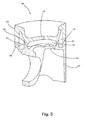
- Piston 60 shown in Fig. 6 has one single cooling chamber 61 formed between the wall section 62 into which the combustion cavity 63 of the piston 60 is moulded and the wall section 64 which forms the top of the piston skirt part 65 of piston 60.
- the cooling chamber 61 extends between the outer wall 66 of the piston 60. Accordingly, the piston head part 67 of the piston 60 is connected with the piston skirt part 65 only by a projection 68 of the outer wall part of the piston skirt part 65 extending into a recess correspondingly formed in the outer wall part of the piston head part 44.
- the positive and non-positive connection between the projection 68 of the skirt part 64 and the recess 69 of the head part 66 is realised in the same manner as the connection between the projection 29 of the piston skirt part 7 and the recess 26 of the piston head part 4 of the piston 1 shown in Fig. 1 .
Abstract
Description
- The invention relates to a piston, having a cooling chamber, for an internal-combustion engine, which piston is made up of two pre-produced parts, and to a method for manufacturing a piston of this type.
- Pistons for internal-combustion engines are conventionally manufactured by casting or forging methods. Production by casting has the advantage of allowing the manufacture of light pistons of complex shape. However, considerable production costs have to be allowed for. This is especially the case if a steel material is to be used as the material for the manufacture of particularly high-strength pistons.
- Depending on their size and on their intended application, forged pistons made of steel can both be of one-part construction and consist of two or more parts. In the case of multi-part pistons, composed of two or more parts, the individual parts are conventionally joined together non-positively, in a material-uniting manner or positively by suitable joining methods in such a way that they withstand the forces acting on them in practical use.
- Specifically in the case of highly stressed diesel engines or highly charged spark-ignition engines, the heads of the pistons inserted in the respective internal-combustion engine are exposed to considerable thermal loads. In order to counteract the danger emanating from these loads, it has long been known to introduce at least one cooling chamber formed as a cooling channel into pistons of this type. The cooling channel can be connected to the atmosphere present in the crank chamber of the respective engine, so air passes through it during operation. To improve the effectiveness of this cooling, it is also known to integrate the cooling channel of a piston into the oil-circulation system of the respective internal-combustion engine.
- A first example of a large number of pistons of this type is described in
EP 0 787 898 A1 . This piston is composed of a piston head part and a piston skirt part. The piston skirt part consists in this case of an intermediate part, which forms the bearing for the bolt of the connecting rod to be linked to the piston, and an outer part forming the piston skirt itself. - In the known piston, there is formed into the underside, associated with the piston skirt part, of the piston head part a recess formed in the manner of a groove and encircling in the outer edge region of the piston head part. Correspondingly, a recess, also formed in the manner of a groove and encircling in the outer edge region of the piston skirt part, is formed in the upper side, associated with the piston skirt part, of the piston skirt part. When the piston is fully assembled, the two recesses jointly form a closed, peripheral cooling channel which is delimited in its upper region by material of the piston head part and in its lower region by material of the piston skirt part. The cooling channel thus formed is in this case connected to the bearing, formed integrally with the piston skirt part, for the connecting rod via a hole guided through the piston skirt part, so during operation the oil conveyed to the bearing of the connecting rod can flow into the cooling channel and discharge the heat present therein.
- In the case of the above-described known piston, the piston skirt and piston head parts, which are pre-produced separately from each other, are connected using a plurality of screws which are screwed from the upper side of the piston head part into the piston skirt part.
- Although the multi-part construction of the known piston allows the cooling channel to be manufactured in a simple manner, the assembly of the known piston is, in particular, complex. The inevitable arrangement of the screw heads of the connecting screws in the combustion cavity of the piston head part also restricts the freedom of the design of a piston of this type.
- Another piston, composed of a plurality of parts, with a cooling channel is described in
WO 00/04286 EP 0 787 898 A1 , the piston head part is composed of an upper part and a lower part receiving the bearing for the connecting rod bolt. The lower part additionally carries, in this case, the sleeve-like piston skirt part. Correspondingly shaped recesses are formed into the mutually associated sides of the piston head upper and lower part. When the piston is fully assembled, the recesses jointly form a cooling channel which is enclosed on its underside by material of the piston head lower part and on its upper side by material of the piston head upper part. The cooling channel can be connected to an oil supply via a hole and an opening. - In the piston known from
WO 00/04286 WO 00/04286 - A further possibility for connecting two parts of a piston for an internal-combustion engine is described in
DE 103 07 908 A1 . In this prior art, the piston has a piston skirt part, the casing portion reaches up to the upper side of the piston, so the grooves for receiving the piston rings can be formed into the upper portion of the piston skirt part. At its upper end, the piston skirt part surrounds an opening into which, as a piston head part, a plate or plug-like piston head part is formed. The external diameter of the piston head part and the internal diameter of the opening in the piston skirt part are, in this case, mutually adapted in such a way that the piston head part is held in the opening in a press fit. At the same time, the underside of the piston head part rests on material of the piston skirt part, so the piston head part is supported against the piston skirt part counter to the drive forces acting on it during practical operation. In addition, screws ensure that the piston head part is secured in the piston skirt part. - Although the piston described in
DE 103 07 908 A1 is intended for high-speed two-stroke engines, no cooling channel is provided in the known piston. Instead, the load capacity of the known piston is to be adapted, by the choice of suitable materials, to the loads resulting during practical use. - A further example of a multi-part piston for an internal-combustion engine is known from
DE 102 44 513 A1 . This piston has firstly a piston head part which is forged from steel and into which a combustion cavity, an annular wall and a cooling channel formed in the manner of a flute are formed. Secondly, the piston has a piston skirt part which carries a piston head part and in which hubs are formed for receiving a piston bolt connecting the piston to a connecting rod. For the manufacture of this piston, the piston head part and the piston skirt part are pre-produced in separate operations by forging and then finished by metal cutting. The finishing of the piston head part includes, in this case, the metal-cutting machining of the wall portions which delimit the cooling channel and via which a connection, uniting materials by welding or soldering, to the piston skirt part is subsequently produced. - Although a multi-part construction of this type allows complex shaping of the piston formed from two parts, apart from the load-capacity problems resulting from the multi-part construction, the production costs associated therewith are considerable.
- Starting from the above-described prior art, the invention was based on the object of providing a piston for internal-combustion engines, which piston can be manufactured cost-effectively and allows maximum design freedom. A method for manufacturing a piston of this type is also to be specified.
- With regard to the piston, this object was achieved, according to the invention, by a piston configured in accordance with
claim 1. The claims dependent onclaim 1 specify advantageous embodiments of such a piston according to the invention. - Particularly suitable for the manufacture of a piston according to the invention is the method specified in
claim 12. Advantageous embodiments of this method according to the invention are specified in the claims dependent onclaim 12. - A piston according to the invention for an internal-combustion engine is made up of at least one first part and a second part, one of the two parts forming the piston head and the other part the piston skirt. At the same time, there is arranged in the piston a cooling chamber which is delimited, in accordance with the prior art described at the outset, by material of the first part and material of the second part. In practise the delimitation of the cooling chamber can be realised for example by at least one wall of the first part and at least one wall of the second part.
- According to the invention, the two parts of a piston of this type are joined together positively and non-positively via a press fit. This press fit is, in this case, formed by a projection of the one part engaging with a recess in the respective other part.
- The invention now applies the possibility, in general previously known from the field of the manufacture of pistons for internal-combustion engines, of connecting two parts via a press fit to the particular problem of the connecting of two piston parts which, when the piston is finished, delimit a cooling chamber. It has surprisingly been found that even in the case of a piston according to the invention having such a composition, a permanently rigid, positive and non-positive connection between the piston head and piston skirt part can be ensured.
- The fundamental advantage of a piston according to the invention is that the form, selected in accordance with the invention, of the connection of the two piston parts can not only be produced cost-effectively but also allows maximum design freedom. In particular, it is readily possible, in the manner according to the invention, to form even cooling chambers of complex shape in the piston. Both the piston head part and the piston skirt part can in this case be pre-produced with high precision, so finishing costs are reduced to a minimum.
- A further important advantage of the invention consists in the simple possibility of being able to combine even the most diverse materials without difficulty. The invention thus allows, for example, the piston head part to be made of a high-strength stainless steel and the piston skirt part to be made of a steel that is less strong but is particularly deformable or has particularly good sliding properties. It is also conceivable to combine a piston head part made of steel, in particular stainless steel, with a piston skirt part made of light metal, in particular an aluminium material.
- The connection, produced in accordance with the invention via at least one press fit, of the two piston parts also allows the press fit to be formed in each case at the location at which it has an optimum effect with regard to the loads occurring during practical operation. The press fit can thus be formed, for example, in the region of the piston wall forming the outer delimitation of the cooling chamber. A press fit of this type, arranged peripherally in the region of the circumference of the piston, allows the risk of opening of the joint seam, inevitably present between the first and the second part of a piston according to the invention, to be reliably minimised.
- Alternatively or additionally, it can also be expedient to form the press fit in a centrally arranged region of the piston. In this embodiment, the comparatively high thicknesses of the walls present in the central region of the piston allow particularly high pressures to be generated between the moulded elements of the piston skirt and piston head part, via which the positive and non-positive connection according to the invention is produced. A particularly operationally secure connection of the two parts of a piston according to the invention is obtained, in this case, if the central pressed fit and the peripheral, outer press fit are combined with each other.
- The at least one cooling chamber of the inventive piston can be a single integral cooling chamber formed in the center of the piston or a cooling channel which surrounds the center of the piston. It is also possible to combine a first cooling chamber placed in the center of the piston and a second cooling chamber in the form of a channel surrounding the central cooling chamber. By the presence of a centrally placed cooling chamber the transfer of heat from the combustion chamber of the engine to the piston skirt is interrupted or at least decisively limited so that the surface temperature of the combustion cavity of the piston rises. Accordingly, the combustion of fuel in the combustion chamber of the engine takes place at high temperatures so that the chemical energy of the fuel can be used with a higher efficiency.
- In principle, it is possible to configure a plurality of cooling chambers in the piston head part or in the piston skirt part of a piston according to the invention in order to achieve maximum cooling effect. If the press fit is formed in the central region of the piston, it is particularly possible to guide a cooling chamber formed as a cooling channel of maximum cross section around the central region. If a press fit between the two parts is additionally formed in the outer peripheral region of the piston, the permanent tightness of the press fit can be reliably ensured.
- A simple possibility for the formation of a press fit between the first and second part consists in there being formed into the side of the one part that is associated with the other part, as a recess, a peripheral groove in which, as a projection, a likewise peripheral shoulder of the second part is held positively and non-positively in a press fit.
- Particularly secure cohesion between the at least two parts of a piston according to the invention can be achieved in that there is formed in the region of the recess in the one part an undercut with which a corresponding moulded element of the projection of the second part engages. The undercut of the recess and the corresponding moulded element of the projection are, in this case, to be mutually adapted in such a way that the change in size, caused, for example, by heating of the part provided with the recess and/or cooling of the part provided with the projection, of at least one of the parts is sufficiently great that the projection, despite its moulded element associated with the undercut, can be inserted into the recess substantially without force. After the subsequent adaptation of the temperatures of both parts and the accompanying adaptation of the dimensions of both parts, the moulded element of the one part then engages with the undercut of the other part and additionally supports the positive connection of both parts. Practical tests have revealed that the undercut formed in the region of the recess in the first part is for this purpose to have a contact face for the complementarily shaped moulded element of the projection, which contact face is inclined by > 0° to 5° relative to the direction in which the projection is guided on fitting of the first part into the second part.
- In order, for example, to form the peripherally arranged press fit in the region of the circumference of the piston, the recess in the one part can be configured as a peripheral shoulder with which a correspondingly shaped shoulder of the second part engages as a projection.
- Although it is in principle conceivable to provide for this purpose an additional constructional element, likewise connected in the manner in accordance with the invention to the other parts of a piston according to the invention, a particularly practical embodiment of the invention that can be produced cost-effectively is obtained if a bearing eyelet for a connecting rod bearing is configured on the part of a piston according to the invention that forms the piston skirt.
- The possibility of pre-machining as completely as possible the piston skirt part and the piston head part of a piston according to the invention for internal-combustion engines allows the piston to be manufactured in a particularly simple manner. The method according to the invention accordingly makes provision for a recess to be formed on the first part and a projection to be formed on the second part during the pre-production of the first part, the dimensions of the recess in the one part and of the projection of the other part being mutually adapted in such a way that they can be joined together at room temperature only by means of a press fit. Obviously, there are also formed into the two parts, during the course of the pre-production process, the moulded elements such as, for example, suitably shaped grooves, recesses, etc., which delimit the respective cooling chamber when the piston according to the invention is fully assembled.
- After pre-production, in accordance with the generally conventional procedure for the production of a press-fit, the temperature of at least one of the parts is adjusted in such a way that there is a difference in temperature between the first and the second part. This difference in temperature is to be set to be sufficiently large that at least one of the parts changes its shape, as a result of the change in its temperature accompanying the production of the difference in temperature, in such a way that the projection of the one part can be fitted substantially without force into the recess in the other part. The projection of the one part can then be fitted into the recess in the other part. After the subsequent equalising of the temperature of the one part to the temperature of the other part, the two parts are positively and/or non-positively linked to each other via the pairing "recess in the one part"/"projection of the other part".
- Depending on the expansion properties of each part on heating, it can be beneficial for the first part provided with the recess to be heated for producing the difference in temperature. For this purpose, the respective first part can, for example, be heated to a heating temperature of 100 to 700°C. Practical tests have revealed in this regard that irrespective of the size of each part and the heat source available, a heating period of 5 to 3,600 s is required for this purpose.
- However, alternatively or additionally, it can also be expedient, in a manner known per se, to cool the part provided with the projection for producing the difference in temperature.
- The invention will be described hereinafter in greater detail with reference to drawings illustrating embodiments. In the drawings:
-
Fig. 1 is a schematic, partially cut-open perspective view of a piston for an internal-combustion engine; -
Fig. 2 is a schematic longitudinal section of a detail of the piston shown inFig. 1 ; -
Fig. 3 is a schematic longitudinal section of a detail of a second piston; -
Fig. 4 is a schematic longitudinal section of a detail of a third piston; -
Fig. 5 is a schematic, partially cut-open perspective view of fourth piston for an internal-combustion engine and -
Fig. 6 is a schematic, partially cut-open perspective view of a fifth piston for an internal-combustion engine. - The
pistons 1 to 3 shown in the figures are each of two-part construction and assembled of apiston head part 4, 5, 6 and apiston skirt part piston head parts 4, 5, 6 each consist, in this regard, of a high-strength steel, in particular a stainless steel, whereas thepiston skirt parts - The
piston head parts 4, 5, 6 and thepiston skirt parts piston skirt part piston head parts 4, 5, 6 a respectiveannular depression central region 13 of the respectivepiston head part 4, 5, 6. Acombustion cavity piston head parts 4, 5, 6. - Also in each case formed into the upper side, associated with the respective
piston head part 4, 5, 6, of the respectivepiston skirt parts annular depression piston skirt part depression indentations piston channel 20, 21, 22 which is delimited in its upper region by material of the respectivepiston head part 4, 5, 6 and in its lower region by material of the respectivepiston skirt part - In the lower region of the
piston skirt parts 6, 7, 8, there is formed in a manner known per se arespective bearing eyelet 23 for a bolt (not shown) via which a connecting rod (which can also not be seen) is articulated to therespective piston - In the embodiment shown in
Fig. 1 and2 , there is formed into thecentral region 13 of the piston head part 4, from the underside thereof, a centrally arrangedrecess 24, the opening of which is oriented normally to the longitudinal axis L of the piston 4 and is separated from thedepression 10 in the piston head part 4 by aperipheral shoulder 25. - In the
piston 1, asecond recess 26 which is formed in the manner of a shoulder and encircles in the outer edge region of the piston head part 4 is formed on the inner edge of thewall 27, outwardly delimiting theindentation 10, of the piston head part 4. - In the
piston 1, corresponding to the centrally arrangedrecess 24 in the piston head part 4, aprojection 28 is formed integrally with the upper side, associated with the piston head part 4, of thepiston skirt part 7. In the pre-produced state, not assembled with the piston head part 4, the external diameter thereof is larger by an excess amount than the internal diameter of therecess 24. This excess amount is such that, on the one hand, the expansion of therecess 24 accompanying in the radial direction heating of the piston head part 4 is sufficient to allow theprojection 28 to be introduced into therecess 24 substantially without force and, on the other hand, the surface pressure achieved between the external circumferential surface of theprojection 28 and the internal circumferential surface of therecess 24 after the assembly and cooling of the twoparts 1, 4 is sufficient for reliable and permanent connection of the piston head part 4 to thepiston skirt part 7. - In addition, a likewise annularly
peripheral projection 29, configured in the manner of a shoulder, is formed on the upper side, associated with the piston head part 4, of thepiston skirt part 7, in the wall 27' outwardly delimiting theindentation 17, of thepiston skirt part 7 so as to correspond to theperipheral recess 26, formed in the manner of a shoulder, in the piston head part 4. In the pre-produced but not yet assembled state, its outer circumferential wall is in this case oriented so as to be offset by an excess amount, based on the common longitudinal axis L of thepiston 1, relative to the internal circumferential surface of the shoulder-like recess 26 in the piston head part 4. As in the case of theprojection 28, this excess is such that, on the one hand, the expansion of therecess 26 accompanying in the radial direction heating of the piston head part 4 is sufficient to allow theprojection 29 to be introduced into therecess 26 substantially without force and, on the other hand, the surface pressure achieved between the external circumferential surface of theprojection 29 and the internal circumferential surface of therecess 26 after the assembly and cooling of the twoparts 1, 4 is sufficient to prevent opening of the seam 30 inevitably present between the piston head part 4 and thepiston skirt part 7. - In the
piston 2, arecess 31 formed in the manner of a groove and encircling thecentral region 13 of thepiston head part 5 is formed into thecentral region 13 of thepiston head part 5, from the underside thereof associated with the piston skirt part 8. In addition, afurther recess 32, in the form of a shoulder encircling the outer lower edge of thepiston head part 5, is formed on thepiston head part 5 of thepiston 2. Thecircumferential surface 33 of therecess 32 is in this case inclined by an angle β of approx. 2° relative to the longitudinal axis L of the piston 3 toward the underside of thepiston head part 5, so an undercut H is formed in the region of therecess 32. - Corresponding to the
recess 31, formed in the manner of a groove, in thepiston head part 5, a first shoulder-likeperipheral projection 34 is formed integrally with the upper side, associated with thepiston head part 5, of the piston skirt part 8. In addition, aprojection 35, corresponding to therecess 32, formed in the manner of a shoulder and encircling the circumference of thepiston skirt part 9, is formed on the outer edge of the upper side, associated with thepiston head part 5, of the piston skirt part 8. The internal circumferential surface of theprojection 35 is in this case inclined, so as to correspond to thecircumferential surface 33 of therecess 32, relative to the longitudinal axis L by an angle of approx. 2°. - The position and dimensions of the
recesses projections projections recesses piston head part 5. After equalisation of the temperatures of the piston skirt part 8 andpiston head part 5, there is then between the circumferential surfaces of therecesses projections 34, 35 a surface pressure which is sufficient reliably to hold together the twoparts piston 5 even during practical use. The connection formed in the region of the pairing "recess 31" and "projection 35" by the undercut and the internal circumferential surface, engaging therewith, of theprojection 35 additionally supports this cohesion. - In the piston 6, a
recess 36, in the form of a shoulder encircling the outer lower edge of the piston head part 6, is formed on the piston head part 6, as in thepiston head part 5 of thepiston 5. In addition, on the inner upper edge of thedepression 12, afurther recess 37, in the form of a peripheral shoulder, is formed into the piston head part 6. -
Projections piston skirt part 9, corresponding to therecesses piston skirt part 9 cannot be joined together in the pre-produced state at room temperature; instead, for this purpose, at least the piston head part 6 has to be cooled sufficiently intensively or thepiston skirt part 9 has to be heated sufficiently intensively that the change in the dimensions, associated with this temperature adjustment, of eachpart 6, 9 is sufficient to allow it to be joined to the respectiveother part 9, 6 substantially without force. -
Piston 40 shown inFig. 4 has an coolingchannel 41 formed and positioned similar to the cooling channel 21 ofpiston 2. Additionally a coolingchamber 42 is formed in the central region of thepiston 40 between thewall section 43 in which the combustion cavity of thepiston head part 44 is moulded and thewall section 45 forming the top of thepiston skirt part 46 ofpiston 40. - The positively and non-positively connection between the
piston head part 44 and thepiston skirt part 46 is realised in the same manner as the connection between thepiston head part 5 and the piston skirt part 8 of thepiston 2 shown inFig. 3 . Accordingly, from theskirt part 46 ofpiston 40projections projections piston 2 engage correspondingrecesses piston head part 44 ofpiston 40. -
Piston 60 shown inFig. 6 has onesingle cooling chamber 61 formed between thewall section 62 into which thecombustion cavity 63 of thepiston 60 is moulded and thewall section 64 which forms the top of thepiston skirt part 65 ofpiston 60. - The cooling
chamber 61 extends between theouter wall 66 of thepiston 60. Accordingly, thepiston head part 67 of thepiston 60 is connected with thepiston skirt part 65 only by aprojection 68 of the outer wall part of thepiston skirt part 65 extending into a recess correspondingly formed in the outer wall part of thepiston head part 44. The positive and non-positive connection between theprojection 68 of theskirt part 64 and therecess 69 of thehead part 66 is realised in the same manner as the connection between theprojection 29 of thepiston skirt part 7 and therecess 26 of the piston head part 4 of thepiston 1 shown inFig. 1 . -
- 1, 2, 3
- Piston
- 4, 5, 6
- Piston head part
- 7, 8, 9
- Piston skirt part
- 10, 11, 12
- Depression
- 13
- Central region of the
piston head part 4, 5, 6 - 14, 15, 16
- Combustion cavity
- 17, 18, 19
- Depression
- 20, 21, 22
- Cooling channel
- 23
- Bearing eyelet
- 24
- Recess in the piston head part 4
- 25
- Shoulder of the piston head part 4
- 26
- Recess in the piston head part 4
- 27
- Wall of the piston head part 4#
- 28
- Projection
- 29
- Projection
- 30
- Seam
- 31
- Recess
- 32
- Recess
- 33
- Circumferential surface of the
recess 32 - 34
- Projection
- 35
- Projection
- 36
- Recess
- 37
- Recess
- 38
- Projection
- 39
- Projection
- 40
- Piston
- 41
- Cooling channel
- 42
- Cooling chamber
- 43
- Wall section
- 44
- Piston head part of
piston 40 - 45
- Wall section
- 46
- Piston skirt part of
piston 40 - 47,48
- Projections
- 49,50
- Recesses
- 60
- Piston
- 61
- Cooling chamber
- 62
- Wall section
- 63
- Combustion cavity of the
piston 60 - 64
- Wall section
- 65
- Piston skirt part
- 66
- Outer wall of the
piston 60 - 67
- Piston head part of the
piston 60 - 68
- Projection
- 69
- Recess
- β
- Angle
- H
- Undercut
- L
- Longitudinal axis L of the
pistons 4, 5, 6
Claims (17)
- Piston for an internal-combustion engine made up of a first part and a second part, one of the two parts forming the piston head (4,5,6,44,67) and the other part forming the piston skirt (7,8,9,46,65) and a cooling chamber (20,21,22,41,42,61), which is delimited by material of the first part and by material of the second part, being configured in the piston (1,2,3,40,60), characterised in that the two parts are joined together positively and non-positively via a press fit formed by a projection (28,29;34,35;38,39;48,49;47,50) of the second part, the projection (28,29;34,35;38,39;47,48;68) engaging with a recess (24,26;31,32;36,37;46,49,50;69) in the first part.
- Piston according to claim 1,
characterised in that the press fit is formed in the region of the piston wall (27,27') forming the outer delimitation of the cooling chamber (20,21,22,41,42,61). - Piston according to any one of the preceding claims,
characterised in that the press fit is formed in a centrally arranged region (13) of the piston. - Piston according to claim 3,
characterised in that the cooling chamber (20,21,22,41,42,61) is guided around the central region (13) in which the press fit is produced. - Piston according to any one of the preceding claims,
characterised in that there is formed into the side of the one part that is associated with the other part, as a recess, a peripheral groove (31) in which, as a projection, a likewise peripheral shoulder (34) of the second part is held positively and non-positively in a press fit. - Piston according to any one of the preceding claims,
characterised in that there is formed in the region of the recess (32) in the one part an undercut (H) with which a corresponding moulded element of the projection (35) of the second part engages. - Piston according to claim 6,
characterised in that the undercut (H) formed in the region of the recess (32) in the first part has a contact face (33) for the complementarily shaped moulded element of the projection (35), which contact face is inclined by >0° to 5° relative to the direction in which the projection is guided on fitting of the first part into the second part. - Piston according to any one of the preceding claims,
characterised in that the recess in the one part is configured as a peripheral shoulder (26) with which a correspondingly shaped shoulder (29) of the second part engages as a projection to produce the press fit. - Piston according to any one of the preceding claims,
characterised in that a bearing eyelet (23) for a connecting rod bearing is configured on the part forming the piston skirt (7). - Piston according to any one of the preceding claims,
characterised in that the part forming the piston head is made of a steel and the other part is made of a light metal. - Piston according to any one of the preceding claims,
characterised in that the cooling chamber is formed as a cooling channel. - Method for manufacturing a piston, composed, in accordance with any one of claims 1 to 11, of two parts, for an internal-combustion engine,- in which the first part (4,5,6,44,67) is pre-produced and in this pre-production a recess (24,31,32,36,37) is formed on the first part,- in which the second part is pre-produced and a projection (28,29,34,35,39) is configured on this second part,- wherein the dimensions of the recess (24,31,32,36,37) in the one part and of the projection (28,29,34,35,39) of the other part are mutually adapted in such a way that they can be joined together at room temperature only by means of a press fit,- producing a difference in temperature between the first and the second part in such a way that at least one of the parts changes its shape, as a result of the change in its temperature accompanying the production of the difference in temperature, in such a way that the projection of the one part can be fitted substantially without force into the recess in the other part,- fitting the projection of the one part into the recess in the other part, and- equalising the temperature of the one part to the temperature of the other part, so the two parts are positively and/or non-positively linked to each other via the pairing "recess in the one part (24,31,32,36,37)"/"projection of the other part (28,29,34,35,39)".
- Method according to claim 12,
characterised in that the first part provided with the recess is (24,31,32,36,37) heated for producing the difference in temperature. - Method according to claim 13,
characterised in that the first part is heated to a heating temperature of 100 to 700°C. - Method according to either claim 13 or claim 14,
characterised in that the first part is heated to the respective heating temperature over a period of 5 to 3,600 s. - Method according to any one of claims 12 to 15,
characterised in that the part provided with the projection (28,29,34,35,39) is cooled for producing the difference in temperature. - Method according to any one of claims 12 to 16,
characterised in that an undercut (H) is formed on the first part in the region of the recess (32) therein and in that a moulded element projecting in a complementary manner to the undercut (H) of the recess is produced on the second part in the region of the projection.
Priority Applications (8)
| Application Number | Priority Date | Filing Date | Title |
|---|---|---|---|
| ES07114934T ES2361777T3 (en) | 2007-08-24 | 2007-08-24 | PISTON FOR AN INTERNAL COMBUSTION ENGINE AND PROCEDURE FOR MANUFACTURING A PISTON OF THIS TYPE. |
| EP07114934A EP2028357B1 (en) | 2007-08-24 | 2007-08-24 | Piston for an internal-combustion engine and method for manufacturing a piston of this type |
| AT07114934T ATE502200T1 (en) | 2007-08-24 | 2007-08-24 | PISTON FOR AN INTERNAL COMBUSTION ENGINE AND METHOD FOR PRODUCING SUCH A PISTON |
| DE602007013219T DE602007013219D1 (en) | 2007-08-24 | 2007-08-24 | Piston for an internal combustion engine and method for producing such a piston |
| MX2010002073A MX2010002073A (en) | 2007-08-24 | 2008-08-22 | Piston for an internal-combustion engine and method for manufacturing a piston of this type. |
| US12/674,869 US20110154984A1 (en) | 2007-08-24 | 2008-08-22 | Piston for an Internal-Combustion Engine and Method for Manufacturing a Piston of this Type |
| BRPI0815571-2A2A BRPI0815571A2 (en) | 2007-08-24 | 2008-08-22 | INTERNAL COMBUSTION ENGINE PISTON AND METHOD FOR MANUFACTURING A PISTON OF THIS TYPE |
| PCT/IB2008/002190 WO2009040617A2 (en) | 2007-08-24 | 2008-08-22 | Piston for an internal-combustion engine and method for manufacturing a piston of this type |
Applications Claiming Priority (1)
| Application Number | Priority Date | Filing Date | Title |
|---|---|---|---|
| EP07114934A EP2028357B1 (en) | 2007-08-24 | 2007-08-24 | Piston for an internal-combustion engine and method for manufacturing a piston of this type |
Publications (2)
| Publication Number | Publication Date |
|---|---|
| EP2028357A1 true EP2028357A1 (en) | 2009-02-25 |
| EP2028357B1 EP2028357B1 (en) | 2011-03-16 |
Family
ID=39174498
Family Applications (1)
| Application Number | Title | Priority Date | Filing Date |
|---|---|---|---|
| EP07114934A Active EP2028357B1 (en) | 2007-08-24 | 2007-08-24 | Piston for an internal-combustion engine and method for manufacturing a piston of this type |
Country Status (8)
| Country | Link |
|---|---|
| US (1) | US20110154984A1 (en) |
| EP (1) | EP2028357B1 (en) |
| AT (1) | ATE502200T1 (en) |
| BR (1) | BRPI0815571A2 (en) |
| DE (1) | DE602007013219D1 (en) |
| ES (1) | ES2361777T3 (en) |
| MX (1) | MX2010002073A (en) |
| WO (1) | WO2009040617A2 (en) |
Cited By (4)
| Publication number | Priority date | Publication date | Assignee | Title |
|---|---|---|---|---|
| WO2014140287A1 (en) * | 2013-03-15 | 2014-09-18 | Ks Kolbenschmidt Gmbh | Two-part steel piston, joining process |
| WO2014139750A1 (en) * | 2013-03-15 | 2014-09-18 | Ks Kolbenschmidt Gmbh | Two-piece piston for internal combustion engine (double joined) |
| WO2017191189A1 (en) * | 2016-05-04 | 2017-11-09 | Ks Kolbenschmidt Gmbh | Piston |
| RU2691455C1 (en) * | 2018-01-09 | 2019-06-14 | Эмель Борисович Ахметов | Internal combustion engine for diesel, gas-diesel or gas motor fuel with spark ignition |
Families Citing this family (8)
| Publication number | Priority date | Publication date | Assignee | Title |
|---|---|---|---|---|
| KR101373805B1 (en) * | 2009-11-26 | 2014-03-12 | 기아자동차주식회사 | Gasoline direct injection engine |
| US8776670B2 (en) * | 2010-02-17 | 2014-07-15 | Mahle International Gmbh | Piston assembly |
| DE102010043837A1 (en) * | 2010-11-12 | 2012-05-16 | Hilti Aktiengesellschaft | Schlagwerkskörper, percussion and hand tool with a striking mechanism |
| DE102011004302A1 (en) | 2011-02-17 | 2012-08-23 | Federal-Mogul Nürnberg GmbH | Method for producing a piston |
| CN102678379A (en) * | 2012-05-25 | 2012-09-19 | 北京理工大学 | Combined piston for highly-intensified reciprocating internal combustion engine |
| DE102012220645B3 (en) * | 2012-11-13 | 2014-04-03 | Federal-Mogul Nürnberg GmbH | Piston for internal combustion engine, has cooling duct that is formed entirely in cast-on upper portion made from aluminum or aluminum alloy, and ring box that is formed in base portion made from steel |
| DE102015201633A1 (en) * | 2015-01-30 | 2016-08-04 | Federal-Mogul Nürnberg GmbH | Piston for an internal combustion engine and method for producing the piston for an internal combustion engine |
| CN104747312A (en) * | 2015-02-16 | 2015-07-01 | 山东滨州渤海活塞股份有限公司 | Internal combustion engine piston with internal cooling oil cavity structure and internal combustion engine |
Citations (8)
| Publication number | Priority date | Publication date | Assignee | Title |
|---|---|---|---|---|
| GB1502790A (en) * | 1976-11-12 | 1978-03-01 | Wellworthy Ltd | Pistons |
| JPH02115556A (en) * | 1988-10-25 | 1990-04-27 | Ngk Insulators Ltd | Ceramics-inserted piston |
| EP0787898A1 (en) | 1996-02-01 | 1997-08-06 | KOLBENSCHMIDT Aktiengesellschaft | Articulated multiparts piston |
| WO2000004286A1 (en) | 1998-07-16 | 2000-01-27 | Federal-Mogul Corporation | Piston having a tube to deliver oil for cooling a crown |
| DE10244513A1 (en) | 2002-09-25 | 2004-04-08 | Mahle Gmbh | Multi-part cooled piston for an internal combustion engine and method for its production |
| DE10307908A1 (en) | 2003-02-19 | 2004-09-09 | Andreas Mozzi | Multi-part piston |
| DE102004058968A1 (en) * | 2004-12-08 | 2006-06-14 | Mahle International Gmbh | Two-piece piston for an internal combustion engine |
| US20070283917A1 (en) * | 2006-06-12 | 2007-12-13 | Lapp Michael T | Piston for a combustion engine |
Family Cites Families (19)
| Publication number | Priority date | Publication date | Assignee | Title |
|---|---|---|---|---|
| US2537174A (en) * | 1948-12-15 | 1951-01-09 | Thompson Prod Inc | Coolant filled piston |
| US3475804A (en) * | 1966-10-31 | 1969-11-04 | Int Harvester Co | Internal combustion engine piston with pre-stressed insert |
| US3613521A (en) * | 1968-11-07 | 1971-10-19 | Komatsu Mfg Co Ltd | Piston for internal combustion engine |
| FR2142146A5 (en) * | 1971-06-14 | 1973-01-26 | Bechir Roger | |
| DE3237469C2 (en) * | 1982-10-09 | 1984-08-09 | Feldmühle AG, 4000 Düsseldorf | Piston with a component made from partially stabilized zirconium oxide |
| GB8804533D0 (en) * | 1988-02-26 | 1988-03-30 | Wellworthy Ltd | Pistons |
| BR8803970A (en) * | 1988-07-15 | 1990-03-20 | Metal Leve Sa | REFRIGERATED ARTICULATED PUMP |
| US6003479A (en) * | 1997-05-12 | 1999-12-21 | Evans; Mark M. | Piston construction |
| US6112642A (en) * | 1998-10-06 | 2000-09-05 | Caterpillar Inc. | Method and apparatus for making a two piece unitary piston |
| AU2459201A (en) * | 1999-12-30 | 2001-07-16 | Federal Mogul Corporation | Piston having uncoupled skirt |
| US6668703B2 (en) * | 2000-10-03 | 2003-12-30 | Christopher Gamble | Piston with oil trap |
| AU2003233547A1 (en) * | 2002-05-15 | 2003-12-02 | Deltahawk Engines, Inc. | A lubricant-cooled and wristpin lubricating piston |
| DE102004028459A1 (en) * | 2004-06-11 | 2005-12-29 | Mahle Gmbh | Built piston for internal combustion engine consists of upper part with bearing edge, recess and nose part on bottom and under part shaped to form a shrink fit with upper part thereby joining them together |
| US7104183B2 (en) * | 2004-07-07 | 2006-09-12 | Karl Schmidt Unisia, Inc. | One-piece steel piston |
| US20060086325A1 (en) * | 2004-10-25 | 2006-04-27 | Ipd, Inc. | Two piece cast ferrous crown piston for internal combustion engine |
| US20070295299A1 (en) * | 2006-06-12 | 2007-12-27 | Mahle Technology, Inc. | Piston for a combustion engine |
| ATE494469T1 (en) * | 2006-09-26 | 2011-01-15 | Thyssenkrupp Metalurgica Campo Limpo Ltda | METHOD FOR PRODUCING A PISTON FOR INTERNAL COMBUSTION ENGINE AND PISTON FOR AN INTERNAL COMBUSTION ENGINE |
| US7533601B2 (en) * | 2006-12-12 | 2009-05-19 | Mahle Technology, Inc. | Multi-part piston for a combustion engine |
| US8171842B2 (en) * | 2007-06-20 | 2012-05-08 | Mahle International Gmbh | Two-piece twist lock piston |
-
2007
- 2007-08-24 ES ES07114934T patent/ES2361777T3/en active Active
- 2007-08-24 AT AT07114934T patent/ATE502200T1/en not_active IP Right Cessation
- 2007-08-24 DE DE602007013219T patent/DE602007013219D1/en active Active
- 2007-08-24 EP EP07114934A patent/EP2028357B1/en active Active
-
2008
- 2008-08-22 BR BRPI0815571-2A2A patent/BRPI0815571A2/en not_active Application Discontinuation
- 2008-08-22 WO PCT/IB2008/002190 patent/WO2009040617A2/en active Application Filing
- 2008-08-22 MX MX2010002073A patent/MX2010002073A/en active IP Right Grant
- 2008-08-22 US US12/674,869 patent/US20110154984A1/en not_active Abandoned
Patent Citations (8)
| Publication number | Priority date | Publication date | Assignee | Title |
|---|---|---|---|---|
| GB1502790A (en) * | 1976-11-12 | 1978-03-01 | Wellworthy Ltd | Pistons |
| JPH02115556A (en) * | 1988-10-25 | 1990-04-27 | Ngk Insulators Ltd | Ceramics-inserted piston |
| EP0787898A1 (en) | 1996-02-01 | 1997-08-06 | KOLBENSCHMIDT Aktiengesellschaft | Articulated multiparts piston |
| WO2000004286A1 (en) | 1998-07-16 | 2000-01-27 | Federal-Mogul Corporation | Piston having a tube to deliver oil for cooling a crown |
| DE10244513A1 (en) | 2002-09-25 | 2004-04-08 | Mahle Gmbh | Multi-part cooled piston for an internal combustion engine and method for its production |
| DE10307908A1 (en) | 2003-02-19 | 2004-09-09 | Andreas Mozzi | Multi-part piston |
| DE102004058968A1 (en) * | 2004-12-08 | 2006-06-14 | Mahle International Gmbh | Two-piece piston for an internal combustion engine |
| US20070283917A1 (en) * | 2006-06-12 | 2007-12-13 | Lapp Michael T | Piston for a combustion engine |
Cited By (8)
| Publication number | Priority date | Publication date | Assignee | Title |
|---|---|---|---|---|
| WO2014140287A1 (en) * | 2013-03-15 | 2014-09-18 | Ks Kolbenschmidt Gmbh | Two-part steel piston, joining process |
| WO2014139750A1 (en) * | 2013-03-15 | 2014-09-18 | Ks Kolbenschmidt Gmbh | Two-piece piston for internal combustion engine (double joined) |
| CN105143652A (en) * | 2013-03-15 | 2015-12-09 | Ks科尔本施密特有限公司 | Two-piece piston for internal combustion engine (double joined) |
| US20160025034A1 (en) * | 2013-03-15 | 2016-01-28 | Ks Kolbenschmidt Gmbh | Two-piece piston for internal combustion engine (double joined) |
| WO2017191189A1 (en) * | 2016-05-04 | 2017-11-09 | Ks Kolbenschmidt Gmbh | Piston |
| CN109312688A (en) * | 2016-05-04 | 2019-02-05 | Ks科尔本施密特有限公司 | Piston |
| US11162453B2 (en) | 2016-05-04 | 2021-11-02 | Ks Kolbenschmidt Gmbh | Piston |
| RU2691455C1 (en) * | 2018-01-09 | 2019-06-14 | Эмель Борисович Ахметов | Internal combustion engine for diesel, gas-diesel or gas motor fuel with spark ignition |
Also Published As
| Publication number | Publication date |
|---|---|
| ATE502200T1 (en) | 2011-04-15 |
| EP2028357B1 (en) | 2011-03-16 |
| US20110154984A1 (en) | 2011-06-30 |
| BRPI0815571A2 (en) | 2015-02-18 |
| WO2009040617A3 (en) | 2010-04-01 |
| DE602007013219D1 (en) | 2011-04-28 |
| WO2009040617A2 (en) | 2009-04-02 |
| ES2361777T3 (en) | 2011-06-22 |
| MX2010002073A (en) | 2010-05-20 |
Similar Documents
| Publication | Publication Date | Title |
|---|---|---|
| EP2028357B1 (en) | Piston for an internal-combustion engine and method for manufacturing a piston of this type | |
| US8950375B2 (en) | Piston for an internal combustion engine | |
| JP4909280B2 (en) | Connecting rod assembly for internal combustion engine and method of manufacturing the same | |
| US20070079775A1 (en) | Welding Forged Steel Single Piece Piston and Its Manufacturing Methods | |
| JP4838808B2 (en) | Method of manufacturing a connecting rod assembly for an internal combustion engine | |
| US20080121205A1 (en) | Piston For A Combustion Engine | |
| US6318243B1 (en) | Two-piece piston assembly | |
| CN101092914A (en) | Welding type single piece piston in forged steel with close internal cooling oil pocket and fabricating method | |
| KR20080043300A (en) | Piston for an internal combustion engine | |
| US5040454A (en) | Piston assembly and piston member thereof having a predetermined compression height to diameter ratio | |
| CN101189424A (en) | Two-part piston for a combustion engine | |
| US8613137B2 (en) | Connecting rod lubrication recess | |
| WO2013004364A1 (en) | Piston with cooling gallery | |
| US6499387B2 (en) | Unified multi-piece piston and method of manufacture | |
| US9702317B2 (en) | Double welded steel piston with full skirt | |
| EP1322852A1 (en) | Piston for internal combustion engine | |
| US9291119B2 (en) | Piston assembly with preloaded support surfaces | |
| EP2812612B1 (en) | Piston and cooled piston ring therefor and method of construction thereof | |
| US20140174400A1 (en) | Split-angle connecting rod | |
| EP0393142B1 (en) | Piston assembly and piston member thereof having a predetermined compression height to diameter ratio | |
| KR101700704B1 (en) | Method of manufacturing the aluminum alloy forged piston | |
| JP2700701B2 (en) | Piston for internal combustion engine | |
| KR102267019B1 (en) | Piston with increasing wear resistance of Piston ring and and method for manufacturing this same | |
| JP4278138B2 (en) | Wear-resistant ring with cooling cavity | |
| JPH11294258A (en) | Piston for internal combustion engine and its assembling method |
Legal Events
| Date | Code | Title | Description |
|---|---|---|---|
| PUAI | Public reference made under article 153(3) epc to a published international application that has entered the european phase |
Free format text: ORIGINAL CODE: 0009012 |
|
| AK | Designated contracting states |
Kind code of ref document: A1 Designated state(s): AT BE BG CH CY CZ DE DK EE ES FI FR GB GR HU IE IS IT LI LT LU LV MC MT NL PL PT RO SE SI SK TR |
|
| AX | Request for extension of the european patent |
Extension state: AL BA HR MK RS |
|
| AKX | Designation fees paid |
Designated state(s): AT BE BG CH CY CZ DE DK EE ES FI FR GB GR HU IE IS IT LI LT LU LV MC MT NL PL PT RO SE SI SK TR |
|
| 17P | Request for examination filed |
Effective date: 20090825 |
|
| 17Q | First examination report despatched |
Effective date: 20091111 |
|
| GRAP | Despatch of communication of intention to grant a patent |
Free format text: ORIGINAL CODE: EPIDOSNIGR1 |
|
| GRAS | Grant fee paid |
Free format text: ORIGINAL CODE: EPIDOSNIGR3 |
|
| RIN1 | Information on inventor provided before grant (corrected) |
Inventor name: OLIVIEEIRA, MAURO APARECIDO FERREIRA DE Inventor name: FURQUIM, HERALDO CARLOS Inventor name: LOPES, JOAO LESTER GARCIA LOPES |
|
| GRAA | (expected) grant |
Free format text: ORIGINAL CODE: 0009210 |
|
| AK | Designated contracting states |
Kind code of ref document: B1 Designated state(s): AT BE BG CH CY CZ DE DK EE ES FI FR GB GR HU IE IS IT LI LT LU LV MC MT NL PL PT RO SE SI SK TR |
|
| REG | Reference to a national code |
Ref country code: GB Ref legal event code: FG4D |
|
| REG | Reference to a national code |
Ref country code: CH Ref legal event code: EP |
|
| REG | Reference to a national code |
Ref country code: IE Ref legal event code: FG4D |
|
| REF | Corresponds to: |
Ref document number: 602007013219 Country of ref document: DE Date of ref document: 20110428 Kind code of ref document: P |
|
| REG | Reference to a national code |
Ref country code: DE Ref legal event code: R096 Ref document number: 602007013219 Country of ref document: DE Effective date: 20110428 |
|
| REG | Reference to a national code |
Ref country code: ES Ref legal event code: FG2A Ref document number: 2361777 Country of ref document: ES Kind code of ref document: T3 Effective date: 20110622 |
|
| REG | Reference to a national code |
Ref country code: NL Ref legal event code: VDEP Effective date: 20110316 |
|
| PG25 | Lapsed in a contracting state [announced via postgrant information from national office to epo] |
Ref country code: LT Free format text: LAPSE BECAUSE OF FAILURE TO SUBMIT A TRANSLATION OF THE DESCRIPTION OR TO PAY THE FEE WITHIN THE PRESCRIBED TIME-LIMIT Effective date: 20110316 Ref country code: LV Free format text: LAPSE BECAUSE OF FAILURE TO SUBMIT A TRANSLATION OF THE DESCRIPTION OR TO PAY THE FEE WITHIN THE PRESCRIBED TIME-LIMIT Effective date: 20110316 Ref country code: SE Free format text: LAPSE BECAUSE OF FAILURE TO SUBMIT A TRANSLATION OF THE DESCRIPTION OR TO PAY THE FEE WITHIN THE PRESCRIBED TIME-LIMIT Effective date: 20110316 Ref country code: GR Free format text: LAPSE BECAUSE OF FAILURE TO SUBMIT A TRANSLATION OF THE DESCRIPTION OR TO PAY THE FEE WITHIN THE PRESCRIBED TIME-LIMIT Effective date: 20110617 |
|
| LTIE | Lt: invalidation of european patent or patent extension |
Effective date: 20110316 |
|
| PG25 | Lapsed in a contracting state [announced via postgrant information from national office to epo] |
Ref country code: SI Free format text: LAPSE BECAUSE OF FAILURE TO SUBMIT A TRANSLATION OF THE DESCRIPTION OR TO PAY THE FEE WITHIN THE PRESCRIBED TIME-LIMIT Effective date: 20110316 Ref country code: AT Free format text: LAPSE BECAUSE OF FAILURE TO SUBMIT A TRANSLATION OF THE DESCRIPTION OR TO PAY THE FEE WITHIN THE PRESCRIBED TIME-LIMIT Effective date: 20110316 Ref country code: FI Free format text: LAPSE BECAUSE OF FAILURE TO SUBMIT A TRANSLATION OF THE DESCRIPTION OR TO PAY THE FEE WITHIN THE PRESCRIBED TIME-LIMIT Effective date: 20110316 Ref country code: CY Free format text: LAPSE BECAUSE OF FAILURE TO SUBMIT A TRANSLATION OF THE DESCRIPTION OR TO PAY THE FEE WITHIN THE PRESCRIBED TIME-LIMIT Effective date: 20110316 Ref country code: BG Free format text: LAPSE BECAUSE OF FAILURE TO SUBMIT A TRANSLATION OF THE DESCRIPTION OR TO PAY THE FEE WITHIN THE PRESCRIBED TIME-LIMIT Effective date: 20110616 |
|
| PG25 | Lapsed in a contracting state [announced via postgrant information from national office to epo] |
Ref country code: BE Free format text: LAPSE BECAUSE OF FAILURE TO SUBMIT A TRANSLATION OF THE DESCRIPTION OR TO PAY THE FEE WITHIN THE PRESCRIBED TIME-LIMIT Effective date: 20110316 |
|
| PG25 | Lapsed in a contracting state [announced via postgrant information from national office to epo] |
Ref country code: PT Free format text: LAPSE BECAUSE OF FAILURE TO SUBMIT A TRANSLATION OF THE DESCRIPTION OR TO PAY THE FEE WITHIN THE PRESCRIBED TIME-LIMIT Effective date: 20110718 Ref country code: EE Free format text: LAPSE BECAUSE OF FAILURE TO SUBMIT A TRANSLATION OF THE DESCRIPTION OR TO PAY THE FEE WITHIN THE PRESCRIBED TIME-LIMIT Effective date: 20110316 |
|
| PG25 | Lapsed in a contracting state [announced via postgrant information from national office to epo] |
Ref country code: CZ Free format text: LAPSE BECAUSE OF FAILURE TO SUBMIT A TRANSLATION OF THE DESCRIPTION OR TO PAY THE FEE WITHIN THE PRESCRIBED TIME-LIMIT Effective date: 20110316 Ref country code: IS Free format text: LAPSE BECAUSE OF FAILURE TO SUBMIT A TRANSLATION OF THE DESCRIPTION OR TO PAY THE FEE WITHIN THE PRESCRIBED TIME-LIMIT Effective date: 20110716 Ref country code: RO Free format text: LAPSE BECAUSE OF FAILURE TO SUBMIT A TRANSLATION OF THE DESCRIPTION OR TO PAY THE FEE WITHIN THE PRESCRIBED TIME-LIMIT Effective date: 20110316 Ref country code: SK Free format text: LAPSE BECAUSE OF FAILURE TO SUBMIT A TRANSLATION OF THE DESCRIPTION OR TO PAY THE FEE WITHIN THE PRESCRIBED TIME-LIMIT Effective date: 20110316 |
|
| PLBI | Opposition filed |
Free format text: ORIGINAL CODE: 0009260 |
|
| PG25 | Lapsed in a contracting state [announced via postgrant information from national office to epo] |
Ref country code: NL Free format text: LAPSE BECAUSE OF FAILURE TO SUBMIT A TRANSLATION OF THE DESCRIPTION OR TO PAY THE FEE WITHIN THE PRESCRIBED TIME-LIMIT Effective date: 20110316 Ref country code: MT Free format text: LAPSE BECAUSE OF FAILURE TO SUBMIT A TRANSLATION OF THE DESCRIPTION OR TO PAY THE FEE WITHIN THE PRESCRIBED TIME-LIMIT Effective date: 20110316 |
|
| PLAX | Notice of opposition and request to file observation + time limit sent |
Free format text: ORIGINAL CODE: EPIDOSNOBS2 |
|
| 26 | Opposition filed |
Opponent name: KS KOLBENSCHMIDT GMBH Effective date: 20111215 |
|
| PG25 | Lapsed in a contracting state [announced via postgrant information from national office to epo] |
Ref country code: PL Free format text: LAPSE BECAUSE OF FAILURE TO SUBMIT A TRANSLATION OF THE DESCRIPTION OR TO PAY THE FEE WITHIN THE PRESCRIBED TIME-LIMIT Effective date: 20110316 |
|
| REG | Reference to a national code |
Ref country code: DE Ref legal event code: R026 Ref document number: 602007013219 Country of ref document: DE Effective date: 20111215 |
|
| PG25 | Lapsed in a contracting state [announced via postgrant information from national office to epo] |
Ref country code: MC Free format text: LAPSE BECAUSE OF NON-PAYMENT OF DUE FEES Effective date: 20110831 |
|
| REG | Reference to a national code |
Ref country code: CH Ref legal event code: PL |
|
| PG25 | Lapsed in a contracting state [announced via postgrant information from national office to epo] |
Ref country code: CH Free format text: LAPSE BECAUSE OF NON-PAYMENT OF DUE FEES Effective date: 20110831 Ref country code: LI Free format text: LAPSE BECAUSE OF NON-PAYMENT OF DUE FEES Effective date: 20110831 |
|
| PLBB | Reply of patent proprietor to notice(s) of opposition received |
Free format text: ORIGINAL CODE: EPIDOSNOBS3 |
|
| REG | Reference to a national code |
Ref country code: IE Ref legal event code: MM4A |
|
| PG25 | Lapsed in a contracting state [announced via postgrant information from national office to epo] |
Ref country code: IE Free format text: LAPSE BECAUSE OF NON-PAYMENT OF DUE FEES Effective date: 20110824 |
|
| PG25 | Lapsed in a contracting state [announced via postgrant information from national office to epo] |
Ref country code: LU Free format text: LAPSE BECAUSE OF NON-PAYMENT OF DUE FEES Effective date: 20110824 |
|
| REG | Reference to a national code |
Ref country code: DE Ref legal event code: R100 Ref document number: 602007013219 Country of ref document: DE |
|
| PLCK | Communication despatched that opposition was rejected |
Free format text: ORIGINAL CODE: EPIDOSNREJ1 |
|
| APBM | Appeal reference recorded |
Free format text: ORIGINAL CODE: EPIDOSNREFNO |
|
| APBP | Date of receipt of notice of appeal recorded |
Free format text: ORIGINAL CODE: EPIDOSNNOA2O |
|
| APAH | Appeal reference modified |
Free format text: ORIGINAL CODE: EPIDOSCREFNO |
|
| PG25 | Lapsed in a contracting state [announced via postgrant information from national office to epo] |
Ref country code: TR Free format text: LAPSE BECAUSE OF FAILURE TO SUBMIT A TRANSLATION OF THE DESCRIPTION OR TO PAY THE FEE WITHIN THE PRESCRIBED TIME-LIMIT Effective date: 20110316 |
|
| PG25 | Lapsed in a contracting state [announced via postgrant information from national office to epo] |
Ref country code: HU Free format text: LAPSE BECAUSE OF FAILURE TO SUBMIT A TRANSLATION OF THE DESCRIPTION OR TO PAY THE FEE WITHIN THE PRESCRIBED TIME-LIMIT Effective date: 20110316 |
|
| APBQ | Date of receipt of statement of grounds of appeal recorded |
Free format text: ORIGINAL CODE: EPIDOSNNOA3O |
|
| REG | Reference to a national code |
Ref country code: FR Ref legal event code: PLFP Year of fee payment: 9 |
|
| APBU | Appeal procedure closed |
Free format text: ORIGINAL CODE: EPIDOSNNOA9O |
|
| PLBN | Opposition rejected |
Free format text: ORIGINAL CODE: 0009273 |
|
| STAA | Information on the status of an ep patent application or granted ep patent |
Free format text: STATUS: OPPOSITION REJECTED |
|
| REG | Reference to a national code |
Ref country code: FR Ref legal event code: PLFP Year of fee payment: 10 |
|
| 27O | Opposition rejected |
Effective date: 20130625 |
|
| REG | Reference to a national code |
Ref country code: FR Ref legal event code: PLFP Year of fee payment: 11 |
|
| PGFP | Annual fee paid to national office [announced via postgrant information from national office to epo] |
Ref country code: CH Payment date: 20170523 Year of fee payment: 5 |
|
| REG | Reference to a national code |
Ref country code: FR Ref legal event code: PLFP Year of fee payment: 12 |
|
| PGFP | Annual fee paid to national office [announced via postgrant information from national office to epo] |
Ref country code: IT Payment date: 20180830 Year of fee payment: 12 Ref country code: FR Payment date: 20180827 Year of fee payment: 12 Ref country code: DE Payment date: 20180823 Year of fee payment: 12 |
|
| PGFP | Annual fee paid to national office [announced via postgrant information from national office to epo] |
Ref country code: GB Payment date: 20180822 Year of fee payment: 12 |
|
| REG | Reference to a national code |
Ref country code: ES Ref legal event code: FD2A Effective date: 20190918 |
|
| PG25 | Lapsed in a contracting state [announced via postgrant information from national office to epo] |
Ref country code: ES Free format text: LAPSE BECAUSE OF NON-PAYMENT OF DUE FEES Effective date: 20180825 |
|
| REG | Reference to a national code |
Ref country code: DE Ref legal event code: R119 Ref document number: 602007013219 Country of ref document: DE |
|
| GBPC | Gb: european patent ceased through non-payment of renewal fee |
Effective date: 20190824 |
|
| PG25 | Lapsed in a contracting state [announced via postgrant information from national office to epo] |
Ref country code: DE Free format text: LAPSE BECAUSE OF NON-PAYMENT OF DUE FEES Effective date: 20200303 Ref country code: FR Free format text: LAPSE BECAUSE OF NON-PAYMENT OF DUE FEES Effective date: 20190831 |
|
| PG25 | Lapsed in a contracting state [announced via postgrant information from national office to epo] |
Ref country code: GB Free format text: LAPSE BECAUSE OF NON-PAYMENT OF DUE FEES Effective date: 20190824 Ref country code: IT Free format text: LAPSE BECAUSE OF NON-PAYMENT OF DUE FEES Effective date: 20190824 |