EP1529953B1 - Einrichtung zur Kraftstoffversorgung für ein Fahrzeug - Google Patents
Einrichtung zur Kraftstoffversorgung für ein Fahrzeug Download PDFInfo
- Publication number
- EP1529953B1 EP1529953B1 EP04025857A EP04025857A EP1529953B1 EP 1529953 B1 EP1529953 B1 EP 1529953B1 EP 04025857 A EP04025857 A EP 04025857A EP 04025857 A EP04025857 A EP 04025857A EP 1529953 B1 EP1529953 B1 EP 1529953B1
- Authority
- EP
- European Patent Office
- Prior art keywords
- fuel
- engine
- buffer tank
- vehicle
- tank
- Prior art date
- Legal status (The legal status is an assumption and is not a legal conclusion. Google has not performed a legal analysis and makes no representation as to the accuracy of the status listed.)
- Expired - Lifetime
Links
Images

Classifications
-
- F—MECHANICAL ENGINEERING; LIGHTING; HEATING; WEAPONS; BLASTING
- F02—COMBUSTION ENGINES; HOT-GAS OR COMBUSTION-PRODUCT ENGINE PLANTS
- F02M—SUPPLYING COMBUSTION ENGINES IN GENERAL WITH COMBUSTIBLE MIXTURES OR CONSTITUENTS THEREOF
- F02M37/00—Apparatus or systems for feeding liquid fuel from storage containers to carburettors or fuel-injection apparatus; Arrangements for purifying liquid fuel specially adapted for, or arranged on, internal-combustion engines
- F02M37/0047—Layout or arrangement of systems for feeding fuel
-
- B—PERFORMING OPERATIONS; TRANSPORTING
- B60—VEHICLES IN GENERAL
- B60K—ARRANGEMENT OR MOUNTING OF PROPULSION UNITS OR OF TRANSMISSIONS IN VEHICLES; ARRANGEMENT OR MOUNTING OF PLURAL DIVERSE PRIME-MOVERS IN VEHICLES; AUXILIARY DRIVES FOR VEHICLES; INSTRUMENTATION OR DASHBOARDS FOR VEHICLES; ARRANGEMENTS IN CONNECTION WITH COOLING, AIR INTAKE, GAS EXHAUST OR FUEL SUPPLY OF PROPULSION UNITS IN VEHICLES
- B60K15/00—Arrangement in connection with fuel supply of combustion engines or other fuel consuming energy converters, e.g. fuel cells; Mounting or construction of fuel tanks
- B60K15/03—Fuel tanks
- B60K15/077—Fuel tanks with means modifying or controlling distribution or motion of fuel, e.g. to prevent noise, surge, splash or fuel starvation
-
- F—MECHANICAL ENGINEERING; LIGHTING; HEATING; WEAPONS; BLASTING
- F02—COMBUSTION ENGINES; HOT-GAS OR COMBUSTION-PRODUCT ENGINE PLANTS
- F02M—SUPPLYING COMBUSTION ENGINES IN GENERAL WITH COMBUSTIBLE MIXTURES OR CONSTITUENTS THEREOF
- F02M37/00—Apparatus or systems for feeding liquid fuel from storage containers to carburettors or fuel-injection apparatus; Arrangements for purifying liquid fuel specially adapted for, or arranged on, internal-combustion engines
- F02M37/0047—Layout or arrangement of systems for feeding fuel
- F02M37/007—Layout or arrangement of systems for feeding fuel characterised by its use in vehicles, in stationary plants or in small engines, e.g. hand held tools
-
- F—MECHANICAL ENGINEERING; LIGHTING; HEATING; WEAPONS; BLASTING
- F02—COMBUSTION ENGINES; HOT-GAS OR COMBUSTION-PRODUCT ENGINE PLANTS
- F02M—SUPPLYING COMBUSTION ENGINES IN GENERAL WITH COMBUSTIBLE MIXTURES OR CONSTITUENTS THEREOF
- F02M37/00—Apparatus or systems for feeding liquid fuel from storage containers to carburettors or fuel-injection apparatus; Arrangements for purifying liquid fuel specially adapted for, or arranged on, internal-combustion engines
- F02M37/0076—Details of the fuel feeding system related to the fuel tank
- F02M37/0088—Multiple separate fuel tanks or tanks being at least partially partitioned
-
- B—PERFORMING OPERATIONS; TRANSPORTING
- B60—VEHICLES IN GENERAL
- B60K—ARRANGEMENT OR MOUNTING OF PROPULSION UNITS OR OF TRANSMISSIONS IN VEHICLES; ARRANGEMENT OR MOUNTING OF PLURAL DIVERSE PRIME-MOVERS IN VEHICLES; AUXILIARY DRIVES FOR VEHICLES; INSTRUMENTATION OR DASHBOARDS FOR VEHICLES; ARRANGEMENTS IN CONNECTION WITH COOLING, AIR INTAKE, GAS EXHAUST OR FUEL SUPPLY OF PROPULSION UNITS IN VEHICLES
- B60K15/00—Arrangement in connection with fuel supply of combustion engines or other fuel consuming energy converters, e.g. fuel cells; Mounting or construction of fuel tanks
- B60K15/03—Fuel tanks
- B60K2015/03118—Multiple tanks, i.e. two or more separate tanks
- B60K2015/03138—Pumping means between the compartments
-
- B—PERFORMING OPERATIONS; TRANSPORTING
- B60—VEHICLES IN GENERAL
- B60K—ARRANGEMENT OR MOUNTING OF PROPULSION UNITS OR OF TRANSMISSIONS IN VEHICLES; ARRANGEMENT OR MOUNTING OF PLURAL DIVERSE PRIME-MOVERS IN VEHICLES; AUXILIARY DRIVES FOR VEHICLES; INSTRUMENTATION OR DASHBOARDS FOR VEHICLES; ARRANGEMENTS IN CONNECTION WITH COOLING, AIR INTAKE, GAS EXHAUST OR FUEL SUPPLY OF PROPULSION UNITS IN VEHICLES
- B60K15/00—Arrangement in connection with fuel supply of combustion engines or other fuel consuming energy converters, e.g. fuel cells; Mounting or construction of fuel tanks
- B60K15/03—Fuel tanks
- B60K2015/03118—Multiple tanks, i.e. two or more separate tanks
- B60K2015/03144—Fluid connections between the tanks
-
- B—PERFORMING OPERATIONS; TRANSPORTING
- B60—VEHICLES IN GENERAL
- B60K—ARRANGEMENT OR MOUNTING OF PROPULSION UNITS OR OF TRANSMISSIONS IN VEHICLES; ARRANGEMENT OR MOUNTING OF PLURAL DIVERSE PRIME-MOVERS IN VEHICLES; AUXILIARY DRIVES FOR VEHICLES; INSTRUMENTATION OR DASHBOARDS FOR VEHICLES; ARRANGEMENTS IN CONNECTION WITH COOLING, AIR INTAKE, GAS EXHAUST OR FUEL SUPPLY OF PROPULSION UNITS IN VEHICLES
- B60K15/00—Arrangement in connection with fuel supply of combustion engines or other fuel consuming energy converters, e.g. fuel cells; Mounting or construction of fuel tanks
- B60K15/03—Fuel tanks
- B60K2015/03328—Arrangements or special measures related to fuel tanks or fuel handling
- B60K2015/03414—Arrangements or special measures related to fuel tanks or fuel handling associated with the fuel tank for cooling heated fuel
-
- F—MECHANICAL ENGINEERING; LIGHTING; HEATING; WEAPONS; BLASTING
- F02—COMBUSTION ENGINES; HOT-GAS OR COMBUSTION-PRODUCT ENGINE PLANTS
- F02B—INTERNAL-COMBUSTION PISTON ENGINES; COMBUSTION ENGINES IN GENERAL
- F02B3/00—Engines characterised by air compression and subsequent fuel addition
- F02B3/06—Engines characterised by air compression and subsequent fuel addition with compression ignition
Definitions
- the present invention relates to a fuel supply arrangement for a vehicle, in particular for a rail vehicle, comprising a main tank for receiving fuel to be supplied to an engine of said vehicle in a supply direction.
- Fuel tanks for low floor rail vehicles are commonly located in an underfloor section of the low floor section of the vehicle. In order to reduce their impact on the space available for the passenger compartment off the vehicle, those tanks usually have very long body of little height. Thus, depending on the degree of filling of the tank, the fuel forms a relatively thin layer within the tank. Nevertheless, due to their large dimensions in the horizontal plane, such tanks may take a sufficient amount of fuel.
- Such tanks suffer from several disadvantages.
- One of those disadvantages is caused by the movement of the vehicle. Due to this movement the fuel surface within the tank is subjected to movements as well. As soon as the degree of filling of the tank has fallen below a certain level, this movement of the fuel surface may cause that certain sections of the tank are temporarily not covered with fuel anymore. In the event that this phenomenon occurs in a section where the fuel outlet of the tank towards the engine is located, air is sucked into the fuel lines and the fuel supply towards the engine is at least temporarily interrupted. Depending on the amount of time this situation prevails this may even lead to a stop of the engine despite the fact that there is still a considerable amount of fuel present within the tank. Furthermore, in particular in case of so-called common rail engines, excessive intake of air into the fuel injection system may even cause damage of the injection system, in particular of the injection pump.
- the present invention is based on the technical teaching that continued fuel supply to the engine even at low degrees of filling of the main tank may be ensured in a cost-efficient manner when, in a generic fuel supply arrangement, a buffer tank is provided, said buffer tank being located after the main tank with respect to supply direction and adapted to receive fuel from said main tank and to supply fuel to said engine.
- Fuel supply arrangements for a vehicle with main and buffer tanks are known from US 5 363 814 A and WO 91/14091 A .
- Such a buffer tank may be easily configured in such a manner that the fuel contained therein is less affected by movements of the vehicle.
- a buffer tank may easily be designed to maintain, even at low degrees of filling, a sufficient distance between the moving fuel surface and the fuel outlet leading to the engine. This may be achieved by keeping the buffer tank's dimensions in the horizontal directions small with respect to its dimension in the vertical direction.
- the buffer tank may be effectively avoided that this leads to a contact between the fuel outlet and air contained within the buffer tank. In other words, intake of air into the fuel supply system may be effectively avoided.
- such a buffer tank may be of very simple design leading to low production and implementation costs of the solution according to the present invention.
- a further advantage of the fuel supply arrangement according to the present invention lies in the fact that, thanks to the compensation for fuel supply interruption from the main tank, the main tank may be operated up to lower degrees of filling of the main tank than in previously known systems. Thus, for certain given amount of fuel to be available for supplying the engine, a main tank of smaller dimensions than in the previously known systems may be used. This leads to a gain in space available for the passenger compartment and, thus, an increase in transport capacity and/or passenger comfort.
- the buffer tank may be of any suitable size.
- the buffer tank has a considerably smaller usable volume than said main tank. It is only recommended to provide the buffer tank with a usable volume that ensures uninterrupted fuel supply for a certain amount of time during which the fuel supply from the main tank to the buffer tank is interrupted due to the phenomenon initially described.
- preferred embodiments of the present invention provide for a usable volume of said buffer tank that corresponds to a volume of fuel sufficient to supply the engine for a predetermined first amount of time during normal operation of the engine.
- Said first amount of time is determined as a function of a second amount of time.
- This second amount of time is representative of the maximum amount of time with continuously missing fuel supply to said buffer tank which is to be expected or admissible during normal operation of said vehicle. It will be appreciated, that such a second amount of time may be easily calculated based on theoretical values or assumptions. Furthermore or in addition thereto, it may be calculated from experience values gathered during operation of such vehicles.
- this second amount of time may be a maximum value depending on the maximum amount of time necessary at a certain operating condition of the engine (e.g. at full load operation or at operation with maximum fuel consumption) to travel through any curve on a given railway network the rail vehicle is dedicated to operate on, and on the fuel consumption associated to said operating condition.
- a certain operating condition of the engine e.g. at full load operation or at operation with maximum fuel consumption
- said second amount of time may also be calculated based on other parameters, such as machine parameters. For example, it may be calculated from the maximum time a fuel pump between the main tank at the buffer tank may run dry, i.e. substantially without supplying fuel. Once this maximum value has been reached other measures will have to be taken to prevent damage to fuel pump which are not an object of the present invention.
- Said first amount of time may be equal to said second amount of time.
- it may be calculated from said second amount of time by multiplying said second amount of time by an appropriate security factor.
- a security factor typically ranges from 1 to 2.
- said security factor ranges from 1 to 1.5.
- said first amount of time ranges between 0.5 and 3 minutes at full load operation of the engine.
- said first amount of time ranges between 1 and 2 minutes.
- the fuel may be supplied from the main tank to the buffer tank in any suitable manner.
- fuel supply may be provided by gravity.
- at least one fuel pump is located between the main tank and the buffer tank for supplying fuel from the main tank to the buffer tank in the supply direction. Said fuel pump may be of any suitable design to supply fuel to the buffer tank.
- said fuel pump is adapted to supply fuel to said buffer tank at a first volumetric flow rate, said first volumetric flow rate being at least equal to a second volumetric flow rate to be supplied to said engine.
- Said second volumetric flow rate may be a given constant flow rate, e.g. the maximum volumetric flow rate to be supplied to said engine during normal operation.
- this recovery may take a certain time.
- preferred embodiments of the present invention provide for a first volumetric flow rate that is greater than said second volumetric flow rate.
- the volumetric flow rate of the fuel supply to the buffer tank may not be constant but may be controlled depending on certain appropriate parameters.
- such parameters may be the fuel level within the buffer tank, the actual fuel intake of the engine of or any other suitable parameter permitting to draw conclusions with respect to the actions to be taken to ensure proper fuel supply interrupt compensation.
- a pump control unit connected to said fuel pump for controlling the volumetric flow rate of the fuel supplied to the buffer tank by the fuel pump.
- Said pump control unit is adapted to receive a first signal.
- said pump control unit is adapted to control the volumetric flow rate supplied by said fuel pump as a function of said first signal.
- Said first signal may be representative of any of the parameters mentioned above for controlling the volumetric flow rate supplied by the fuel pump. It may also be representative of any suitable combination of such parameters.
- said first signal is representative of a variable second volumetric flow rate.
- said second volumetric flow rate is an actual volumetric flow rate of the fuel to be supplied to said engine.
- said buffer tank comprises an overflow device for removing excess fuel from said buffer tank.
- an overflow device for removing excess fuel from said buffer tank.
- buffer tank comprises a fuel inlet for receiving excess fuel from the engine via a second fuel return line.
- a second fuel return line may be connected to said fuel inlet, said second fuel return line comprising a fuel cooling device for cooling the fuel supplied to said buffer tank via said second fuel return line.
- a fuel pre-filter is provided between the main tank and the buffer tank.
- a fuel pre-filter is provided between the main tank and the buffer tank.
- the fuel supply arrangement according to present invention may be used at any location within a vehicle. Preferably, it is used for a so-called underfloor arrangement.
- at least the main tank is adapted to be arranged in an underfloor section of said vehicle.
- the fuel supply arrangement according to present invention may be used with any kind of vehicle design. In particular in combination with so-called low floor vehicles the advantages of the present invention come to their full effect.
- at least the main tank is adapted to be arranged in an underfloor section of a low floor section of such a low floor vehicle.
- the present invention further relates to a vehicle, in particular a rail vehicle, comprising an engine and a fuel supply arrangement according to the present invention as previously described.
- Said fuel supply arrangement is connected to said engine for supplying fuel to said engine.
- the buffer tank may be located at any suitable position within the vehicle.
- the buffer tank is located adjacent to the engine.
- said buffer tank is located within an engine compartment of the vehicle, said engine compartment receiving the engine.
- said vehicle is a rail vehicle having a low floor section, said main tank being located in an underfloor section of said low floor section.
- the present invention provides a high degree of freedom with respect to placement of the components of the vehicle.
- the main tank and the engine are not subject to any restrictions with respect to their spatial relationship.
- the engine may be situated in any location deemed to be convenient.
- the engine may, for example, be located in a conventional engine compartment located between a passenger compartment and a driver cabin.
- the engine may also be located in a roof compartment of the vehicle.
- the engine is located in an underfloor section of said vehicle. Such a configuration allows for further enhancement of passenger comfort and transport capacity.
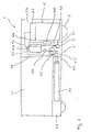
- Figure 1 shows a schematic representation of a low floor rail vehicle 1 according to the present invention having a passenger compartment 1.1, an engine compartment 1.2 and a low floor section 1.3 below the passenger compartment 1.1.
- a common rail diesel engine 2 is located within the engine compartment 1.2.
- the engine 2 serves to provide the power necessary to drive the wheels 3 of the rail vehicle 1 as well as to provide the power necessary for auxiliary units of the rail vehicle 1, such as illumination units, air-conditioning units etc.
- auxiliary units of the rail vehicle 1 such as illumination units, air-conditioning units etc.
- the engine may be, apart from a common rail diesel engine, any other suitable engine to be provided with fuel.
- the engine may, of course, also be dedicated to provide the power for a drive unit or an auxiliary unit exclusively.
- the fuel necessary for driving the engine 1 is provided by a fuel supply arrangement generally denoted by reference numeral 4.
- This fuel supply arrangement 4 comprises a main tank 4.1, a buffer tank 4.2 and a fuel pump 4.3. Via a first fuel line 4.4, the fuel pump 4.3 sucks fuel from the main tank 4.1 and supplies it in a fuel supply direction 4.5 to the buffer tank 4.2. Via a second fuel line 4.6, a common rail fuel injection device 2.1 of the engine 2 sucks fuel from the buffer tank 4.2 and supplies it to the engine 2.
- the buffer tank is located close to the engine 2 within the engine compartment 1.2. This leads to a very short second fuel line 4.6 helping to maintain the strict pressure requirements at the fuel inlet to the injection device 2.1.
- the fuel supply arrangement 4 is designed in such a manner that the fuel supply to the engine is less sensitive to vehicle movement induced movement of the fuel. On the one hand, this is achieved by the buffer tank 4.2 itself. Contrary to the design of the main tank 4.1, the vertical dimensions of the buffer tank 4.2 are not small in relation to its horizontal dimensions. Thus, even at low degrees of filling of the buffer tank 4.2, a sufficient distance between the moving fuel surface and the fuel outlet leading to the second fuel line 4.6 and to the engine 2 is maintained. To increase this effect, the buffer tank's dimensions in the horizontal directions are preferably kept small with respect to its dimension in the vertical direction.
- the buffer tank 4.2 has a considerably smaller usable volume than the main tank 4.1.
- the buffer tank 4.2 has a usable volume that ensures, when completely filled with fuel, uninterrupted fuel supply to the engine 2 for a certain first amount of time during which the fuel supply from the main tank 4.1 to the buffer tank 4.2 is interrupted.
- a fuel supply interruption may be the case when the fuel pump 4.3 sucks air from the main tank 4.1 due to vehicle movement induced movements of the fuel within the main tank 4.1.
- the first amount of time is determined as a function of a second amount of time.
- This second amount of time is representative of the maximum amount of time with continuously missing fuel supply to said buffer tank which is to be expected during normal operation of vehicle 1.
- This second amount of time may be easily calculated based on theoretical values, assumptions and experience values gathered during operation of comparable vehicles.
- the second amount of time may be calculated using statistical information on the curvature, length etc. of the curves to be traveled by the vehicle as well as on the traveling speeds within such curves.
- the first amount of time is calculated from the second amount of time by multiplying said second amount of time by a first security factor of 1.5.
- higher or lower security factors may be chosen depending on the importance of uninterrupted fuel supply during operation of the engine 2.
- the usable volume of the buffer tank is 5 liters. With a specific fuel consumption of about 214 g/kWh, a fuel density of about 0.83 kg/m 3 and an engine power of 662 kW under maximum load conditions, this usable volume is sufficient to supply the engine 2 with fuel for a first amount of time of about 1.8 minutes. With a conventional railway network, any curve will have been traveled through at these operating conditions. Usually, at these operating conditions, any curve will have been traveled through within a second amount of time of about 1.5 minutes. Thus, a security factor of 1.2 has been used.
- the usable volume may also be calculated based on the maximum amount of time the fuel pump 4.3 may run dry, i.e. substantially without supplying fuel. For example, this maximum amount of time may be about 15 minutes.
- the usable volume may be calculated based on the specific consumption of the engine and the power provided by the engine under coasting conditions, i.e. with power being supplied only to auxiliary units. This is due to the fact that such a long interruption of fuel supply from the main tank is only to be expected during such conditions.
- the fuel pump 4.3 is adapted to supply fuel to the buffer tank 4.2 at a first volumetric flow rate which is greater than a second volumetric flow rate to be supplied to the engine 2.
- the second volumetric flow rate is a given constant flow rate, namely the maximum volumetric flow rate to be supplied to the engine 2 during normal operation.
- the buffer tank 4.2 is provided with an overflow device 4.7.
- This overflow device 4.7 comprises a simple fuel outlet of the buffer tank 4.2 connected to a first fuel return line 4.8 leading from the buffer tank 4.2 back to the main tank 4.1.
- additional fuel supply to the buffer tank leads to a fuel return to the main tank 4.1 via the first fuel return line 4.8 of the overflow device 4.7.
- the first volumetric flow rate determined by determined by multiplying the second volumetric flow rate by a second security factor of 1.2 to ensure sufficiently rapid recovery.
- second security factors may be chosen that may be higher or lower mainly depending on the expected delays between subsequent events of interrupted fuel supply to the buffer tank 4.2.
- a second fuel return line 4.9 is connected to a fuel inlet of the buffer tank 4.2.
- This second fuel return line 4.9 returns excess fuel not consumed by the engine 2 back to the buffer tank 4.2.
- the second fuel return line 4.9 is provided with a fuel cooling device 4.10 cooling down the fuel returned from the engine 2 to the buffer tank 4.2 by a desired amount.
- a fuel pre-filter 4.11 is provided between the main tank 4.1 and the buffer tank 4.2, in particular between the fuel pump 4.3 and the buffer tank 4.2. Due to the lower instantaneous flow rates at this location compared to the instantaneous flow rates in the fuel injection device 2.1 of the engine 2, smaller and lighter filters may be used.
- an advantage of the fuel supply arrangement according to the present invention lies in the fact that, thanks to the compensation for fuel supply interruption from the main tank 4.1, the main tank 4.1 may be operated up to lower degrees of filling than in previously known systems.
- the main tank 4.1 may have smaller dimensions than in the previously known systems. In particular, its vertical dimension may be reduced leading to a gain in space available for the passenger compartment 1.1 and, thus; an increase in transport capacity as well as passenger comfort of the vehicle 1.
- the present invention has been described in the context of an embodiment with a fuel pump providing a constant first volumetric flow rate.
- the volumetric flow rate of the fuel supply to the buffer tank may not be constant but may be controlled depending on certain appropriate parameters.
- Figure 2 One such embodiment is shown in Figure 2 .
- This embodiment corresponds in its basic design to the one of Figure 1 .
- identical parts have been denoted by the same reference numerals. With respect to the description of those parts it is here referred to the preceding description with reference to Figure 1 . Only the differences in relation to the embodiment of Figure 1 will be described in the following.
- fuel pump 4.3' is adapted to provide a variable volumetric flow rate.
- a pump control unit 5 connected to the fuel pump 4.3' for controlling the volumetric flow rate of the fuel supplied to the buffer tank 4.2 by the fuel pump 4.3'.
- This pump control unit 5 is adapted to receive a first signal and to control the volumetric flow rate supplied by said fuel pump as a function of said first signal.
- Said first signal may be representative of any of the parameters mentioned above for controlling the volumetric flow rate supplied by the fuel pump 4.3'. It may also be representative of any suitable combination of such parameters.
- said first signal is representative of a variable second volumetric flow rate, said second volumetric flow rate being a mean value of the actual volumetric flow rate of fuel to be supplied to the engine 2.
- This first signal is received by the pump control unit 5 via a first signal line 5.1 from an engine control unit (not shown) of the engine 2.
- the minimum necessary volumetric flow rate to be supplied to the buffer tank 4.2 for maintaining its degree of filling may be selected leading to a minimized energy consumption of the system.
- the pump control unit 5 is further adapted to receive a third signal and to control the volumetric flow rate supplied by the fuel pump 4.3' as a function of said third signal.
- This third signal is representative of the fuel level within the buffer tank 4.2.
- the third signal is provided to the pump control unit 5 via a second signal line 5.2 from a fuel level detector of the buffer tank 4.2 (not shown).
- This consideration of the fuel level within the buffer tank 4.2 allows to appropriately react on situations where, due to several and/or long events with interrupted fuel supply to the buffer tank, the degree of filling of the buffer tank 4.2 reaches a critical level where compensation for such events is not available anymore for a sufficient amount of time. In such a situation the pump control unit 5 may temporarily increase the volumetric flow rate supplied by the fuel pump 4.3' in dependence on the information on the fuel level within the buffer tank 4.2 provided via said third signal.
Landscapes
- Engineering & Computer Science (AREA)
- Chemical & Material Sciences (AREA)
- Combustion & Propulsion (AREA)
- Mechanical Engineering (AREA)
- General Engineering & Computer Science (AREA)
- Life Sciences & Earth Sciences (AREA)
- Sustainable Development (AREA)
- Sustainable Energy (AREA)
- Transportation (AREA)
- Cooling, Air Intake And Gas Exhaust, And Fuel Tank Arrangements In Propulsion Units (AREA)
- Loading And Unloading Of Fuel Tanks Or Ships (AREA)
Claims (18)
- Brennstoffzufuhranordnung für ein Fahrzeug, insbesondere ein Schienenfahrzeug, das einen Haupttank (4.1) zur Aufnahme von Brennstoff, der einem Motor (2) des Fahrzeugs in einer Zufuhrrichtung (4.5) zugeführt wird, und einen Puffertank (4.2) umfasst, wobei der Puffertank (4.2) bezüglich der Zufuhrrichtung nach dem Haupttank (4.1) angeordnet ist und dafür ausgelegt ist Brennstoff vom Haupttank (4.1) zu erhalten und dem Motor (2) Brennstoff zuzuführen, wobei das verwendbare Volumen des Puffertanks (4.2) einem Brennstoffvolumen entspricht, das ausreicht, um den Motor (2) für eine vorbestimmte erste Zeitdauer bei normalem Betrieb des Motors (2) zu versorgen,
dadurch gekennzeichnet, dass
eine erste Zeitdauer als eine Funktion einer zweiten Zeitdauer festgelegt wird, wobei die zweite Zeitdauer repräsentativ ist für die maximale Zeitdauer mit kontinuierlich fehlender Brennstoffzufuhr zum Puffertank (4.2), die bei normalem Betrieb des Fahrzeugs erwartet wird oder zulässig ist. - Brennstoffzufuhranordnung nach Anspruch 1, dadurch gekennzeichnet, dass der Puffertank (4.2) ein beträchtlich kleineres verwendbares Volumen aufweist als der Haupttank (4.1).
- Brennstoffzufuhranordnung nach Anspruch 1 oder 2, dadurch gekennzeichnet, dass die erste Zeitdauer durch Multiplizieren der zweiten Zeitdauer mit einem Sicherheitsfaktor festgelegt wird, wobei der Sicherheitsfaktor in einem Bereich von 1 bis 1,5 liegt.
- Brennstoffzufuhranordnung nach einem der vorhergehenden Ansprüche,
dadurch gekennzeichnet, dass die erste Zeitdauer bei Volllastbetrieb des Motors (2) in einem Bereich zwischen 0,5 und 3 Minuten, insbesondere zwischen 1 und 2 Minuten, liegt. - Brennstoffzufuhranordnung nach einem der vorhergehenden Ansprüche,
gekennzeichnet durch mindestens eine Brennstoffpumpe (4.3; 4.3'), die zwischen dem Haupttank (4.1) und dem Puffertank (4.2) zur Brennstoffzufuhr vom Haupttank (4.1) zum Puffertank (4.2) in der Zufuhrrichtung (4.5) angeordnet ist. - Brennstoffzufuhranordnung nach Anspruch 5, dadurch gekennzeichnet, dass die Brennstoffpumpe (4.3; 4.3') dafür ausgelegt ist, dem Puffertank (4.2) Brennstoff mit einem ersten Volumenstrom zuzuführen, wobei der erste Volumenstrom mindestens gleich wie, bevorzugt größer als, ein zweiter dem Motor (2) zuzuführender Volumenstrom ist.
- Brennstoffzufuhranordnung nach Anspruch 6, dadurch gekennzeichnet, dass der zweite Volumenstrom der maximale Volumenstrom ist, der dem Motor (2) bei normalem Betrieb des Motors zuzuführen ist.
- Brennstoffzufuhranordnung nach Anspruch 6, dadurch gekennzeichnet, dass eine mit der Brennstoffpumpe (4.3') verbundene Pumpenkontrolleinheit (5) vorgesehen ist, zur Kontrolle des Volumenstroms des dem Puffertank (4.2) von der Brennstoffpumpe (4.3') zugeführten Brennstoffs, wobei die Pumpenkontroileinheit (5) dafür ausgelegt ist ein erstes Signal zu erhalten und den von der Brennstoffpumpe (4.3') zugeführten Volumenstrom als eine Funktion des ersten Signals zu kontrollieren, wobei das erste Signal repräsentativ für den zweiten Volumenstrom ist.
- Brennstoffzufuhranordnung nach Anspruch 8, dadurch gekennzeichnet, dass der zweite Volumenstrom ein tatsächlicher Volumenstrom des dem Motor (2) zuzuführenden Brennstoffs ist.
- Brennstoffzufuhranordnung nach einem der vorhergehenden Ansprüche,
dadurch gekennzeichnet, dass der Puffertank (4.2) eine Überlaufvorrichtung (4.7) zum Entfernen von überschüssigem Brennstoff aus dem Puffertank (4.2) aufweist, wobei die Überlaufvorrichtung (4.7) vorzugsweise mit dem Haupttank (4.1) über eine erste Brennstoffrücklaufleitung (4.8) zur Rückführung von überschüssigem Brennstoff zum Haupttank (4.1) entgegen der Zufuhrrichtung (4.5) verbunden ist. - Brennstoffzufuhranordnung nach einem der vorhergehenden Ansprüche,
dadurch gekennzeichnet, dass der Puffertank (4.2) einen Brennstoffeinlass zum Empfangen von überschüssigem Brennstoff vom Motor über eine zweite Brennstoffrücklaufleitung (4.9) aufweist. - Brennstoffzufuhranordnung nach Anspruch 11, gekennzeichnet durch eine zweite Brennstoffrücklaufleitung (4.9), die mit dem Brennstoffeinlass verbunden ist, wobei die zweite Brennstoffrücklaufleitung (4.9) eine Brennstoffkühivorrichtung (4.10) zum Kühlen des dem Puffertank (4.2) über die zweite Brennstoffrücklaufleitung (4.9) zugeführten Brennstoffs aufweist.
- Brennstoffzufuhranordnung nach einem der vorhergehenden Ansprüche,
dadurch gekennzeichnet, dass ein Brennstoffvorfilter (4.11) zwischen dem Haupttank (4.1) und dem Puffertank (4.2) vorgesehen ist. - Brennstoffzufuhranordnung nach einem der vorhergehenden Ansprüche,
dadurch gekennzeichnet, dass der Haupttank (4.1) dafür ausgelegt ist in einem Unterbodenabschnitt (1.3) des Fahrzeugs angeordnet zu sein, insbesondere in einem Unterbodenabschnitt eines niederflurigen Abschnitts des Fahrzeugs. - Fahrzeug, insbesondere Schienenfahrzeug, das einen Motor (2) und eine Brennstoffzufuhranordnung (4; 4') nach einem der vorhergehenden Ansprüche aufweist, die mit dem Motor (2) verbunden ist, um dem Motor (2) Brennstoff zuzuführen.
- Fahrzeug nach Anspruch 15, dadurch gekennzeichnet, dass der Puffertank (4.2) neben dem Motor (2) angeordnet ist, insbesondere innerhalb eines Motorraums (1.2) des Fahrzeugs, der den Motor (2) aufnimmt.
- Fahrzeug nach Anspruch 15 oder 16, dadurch gekennzeichnet, dass es sich um ein Schienenfahrzeug mit einem niederflurigen Abschnitt handelt, wobei der Haupttank in einem Unterbodenabschnitt (1.3) des niederflurigen Abschnitts angeordnet ist.
- Fahrzeug nach einem der Ansprüche 15 bis 17, dadurch gekennzeichnet, dass der Motor (2) in einem Unterbodenabschnitt des Fahrzeugs angeordnet ist.
Priority Applications (1)
| Application Number | Priority Date | Filing Date | Title |
|---|---|---|---|
| PL04025857T PL1529953T3 (pl) | 2003-11-05 | 2004-10-30 | Zespół podawania paliwa dla pojazdu |
Applications Claiming Priority (2)
| Application Number | Priority Date | Filing Date | Title |
|---|---|---|---|
| GB0325909A GB2407802A (en) | 2003-11-05 | 2003-11-05 | Buffer fuel tank arrangement for rail vehicle |
| GB0325909 | 2003-11-05 |
Publications (2)
| Publication Number | Publication Date |
|---|---|
| EP1529953A1 EP1529953A1 (de) | 2005-05-11 |
| EP1529953B1 true EP1529953B1 (de) | 2010-09-29 |
Family
ID=29726047
Family Applications (1)
| Application Number | Title | Priority Date | Filing Date |
|---|---|---|---|
| EP04025857A Expired - Lifetime EP1529953B1 (de) | 2003-11-05 | 2004-10-30 | Einrichtung zur Kraftstoffversorgung für ein Fahrzeug |
Country Status (6)
| Country | Link |
|---|---|
| EP (1) | EP1529953B1 (de) |
| AT (1) | ATE483105T1 (de) |
| DE (1) | DE602004029321D1 (de) |
| GB (1) | GB2407802A (de) |
| HR (1) | HRP20100703T1 (de) |
| PL (1) | PL1529953T3 (de) |
Families Citing this family (5)
| Publication number | Priority date | Publication date | Assignee | Title |
|---|---|---|---|---|
| SE528925C2 (sv) * | 2006-06-19 | 2007-03-20 | Scania Cv Ab | Bufferttank jämte fordon |
| CN102897174B (zh) * | 2012-10-31 | 2015-08-19 | 中国北车集团大连机车车辆有限公司 | 机车冷却系统的液体加注及回收装置 |
| CN108291499B (zh) * | 2015-10-28 | 2020-02-04 | 瓦锡兰芬兰有限公司 | 内燃发动机的多燃料供给系统以及操作该系统的方法 |
| CN108286482A (zh) * | 2017-01-09 | 2018-07-17 | 福油特化工科技(深圳)有限公司 | 半自动乳化油促成系统及方法 |
| SE540432C2 (en) * | 2017-01-17 | 2018-09-18 | Scania Cv Ab | Fuel supply arrangement and ground based vehicle |
Family Cites Families (12)
| Publication number | Priority date | Publication date | Assignee | Title |
|---|---|---|---|---|
| US1983539A (en) * | 1930-07-07 | 1934-12-11 | Int Harvester Co | Steam propelled railway vehicle |
| DE3107141A1 (de) * | 1981-02-26 | 1982-09-09 | Kienzle Apparate Gmbh, 7730 Villingen-Schwenningen | Anordnung zum kuehlen des kraftstoffs in einem betriebssystem eines dieselmotors mit einem geschlossenen einspritzkreislauf |
| EP0086602A1 (de) * | 1982-02-05 | 1983-08-24 | Nigel Carle-Hay | Vorrichtung zur Temperaturregelung von Brennstoff für die Versorgung eines Fahrzeugmotors oder ähnlichem |
| JPS5937258A (ja) * | 1982-08-25 | 1984-02-29 | Hitachi Zosen Corp | 内燃機関の燃料供給装置 |
| JPS6251750A (ja) * | 1985-08-30 | 1987-03-06 | Mitsubishi Heavy Ind Ltd | 燃料油処理装置 |
| DE3707271C1 (de) * | 1987-03-06 | 1988-05-19 | Mannesmann Kienzle Gmbh | Ventilanordnung fuer einen Gasabscheider |
| CA2009408C (en) * | 1989-02-07 | 1995-09-12 | Keisuke Daikoku | Fuel injection type multiple cylinder engine unit |
| ATA52490A (de) * | 1990-03-06 | 1995-10-15 | Frick Peter | Einrichtung zur bestimmung der kraftstoffdurchflussmenge bei verbrennungskraftmaschinen |
| AU657189B2 (en) * | 1992-01-23 | 1995-03-02 | Air Products And Chemicals Inc. | Internal combustion engine with cooling of intake air using refrigeration of liquefied fuel gas |
| US5942127A (en) * | 1993-09-21 | 1999-08-24 | Wilcox; Steven Ian | Fuel oil treatment unit and associated method |
| US5566712A (en) * | 1993-11-26 | 1996-10-22 | White; George W. | Fueling systems |
| US6397759B1 (en) * | 2000-05-11 | 2002-06-04 | Bombardier Inc. | Non-electric locomotive and enclosure for a turbine engine for a non-electric locomotive |
-
2003
- 2003-11-05 GB GB0325909A patent/GB2407802A/en not_active Withdrawn
-
2004
- 2004-10-30 AT AT04025857T patent/ATE483105T1/de not_active IP Right Cessation
- 2004-10-30 EP EP04025857A patent/EP1529953B1/de not_active Expired - Lifetime
- 2004-10-30 PL PL04025857T patent/PL1529953T3/pl unknown
- 2004-10-30 DE DE602004029321T patent/DE602004029321D1/de not_active Expired - Lifetime
-
2010
- 2010-12-20 HR HR20100703T patent/HRP20100703T1/hr unknown
Also Published As
| Publication number | Publication date |
|---|---|
| EP1529953A1 (de) | 2005-05-11 |
| PL1529953T3 (pl) | 2011-03-31 |
| GB2407802A (en) | 2005-05-11 |
| ATE483105T1 (de) | 2010-10-15 |
| GB0325909D0 (en) | 2003-12-10 |
| DE602004029321D1 (de) | 2010-11-11 |
| HRP20100703T1 (hr) | 2011-01-31 |
Similar Documents
| Publication | Publication Date | Title |
|---|---|---|
| JP5838162B2 (ja) | 自動車の燃料タンク | |
| US6792966B2 (en) | Fuel transfer pump and control | |
| CN108136877B (zh) | 用于车辆的多区加热、通风和空调系统的能耗管理和方法 | |
| JPH09324716A (ja) | 車両用燃料ポンプの制御装置 | |
| US9239032B2 (en) | Fuel system and method for operating a fuel system | |
| US11697341B2 (en) | Combined cooling and water braking system for a vehicle, and a method for cooling a propulsion device of a vehicle and water braking a pair of wheels of a vehicle | |
| CN109109646B (zh) | 液压悬置刚度调节系统、刚度调节方法及汽车 | |
| EP3412912B1 (de) | Flüssigkeitsausgabesystem | |
| CN116476630B (zh) | 一种集成式车用副燃油箱 | |
| EP1529953A1 (de) | Einrichtung zur Kraftstoffversorgung für ein Fahrzeug | |
| JPH0655944A (ja) | 車両用燃料タンク | |
| US8955496B2 (en) | Fuel system | |
| US20250289289A1 (en) | Passenger car multi-system integration | |
| CN111186291B (zh) | 一种高置油箱加油装置 | |
| EP1525388B1 (de) | Anordnung zur beförderung von kraftstoff in einem verbrennungsmotor | |
| JP2001173534A (ja) | 燃料供給装置及び燃料ポンプ | |
| WO2004050400A1 (en) | System for heating the cabin of a work machine by using residual heat | |
| SE520422C2 (sv) | Anordning för bränsletransport vid förbränningsmotor | |
| KR20200040293A (ko) | 모터의 에너지 소비에 영향을 주기 위한 방법 | |
| SE0950318A1 (sv) | Bränslesystem, samt fordon innefattande nämnda bränslesystem | |
| JP2011047302A (ja) | 車両の省燃費運転システム | |
| EP1600318A1 (de) | Kraftstoffbehälter für ein Fahrzeug, insbesondere ein Schienenfahrzeug | |
| KR101858197B1 (ko) | 차량에 대한 레인지를 결정하는 방법 및 시스템 | |
| JP2009013969A (ja) | ディーゼルエンジン及び燃温演算装置 | |
| EP4699834A1 (de) | Lüftungsanordnung und fahrzeug |
Legal Events
| Date | Code | Title | Description |
|---|---|---|---|
| PUAI | Public reference made under article 153(3) epc to a published international application that has entered the european phase |
Free format text: ORIGINAL CODE: 0009012 |
|
| AK | Designated contracting states |
Kind code of ref document: A1 Designated state(s): AT BE BG CH CY CZ DE DK EE ES FI FR GB GR HU IE IT LI LU MC NL PL PT RO SE SI SK TR |
|
| AX | Request for extension of the european patent |
Extension state: AL HR LT LV MK |
|
| 17P | Request for examination filed |
Effective date: 20051111 |
|
| AKX | Designation fees paid |
Designated state(s): AT BE BG CH CY CZ DE DK EE ES FI FR GB GR HU IE IT LI LU MC NL PL PT RO SE SI SK TR |
|
| AXX | Extension fees paid |
Extension state: LT Payment date: 20051111 Extension state: HR Payment date: 20051111 Extension state: AL Payment date: 20051111 Extension state: MK Payment date: 20051111 Extension state: LV Payment date: 20051111 |
|
| GRAP | Despatch of communication of intention to grant a patent |
Free format text: ORIGINAL CODE: EPIDOSNIGR1 |
|
| GRAS | Grant fee paid |
Free format text: ORIGINAL CODE: EPIDOSNIGR3 |
|
| GRAA | (expected) grant |
Free format text: ORIGINAL CODE: 0009210 |
|
| RAP1 | Party data changed (applicant data changed or rights of an application transferred) |
Owner name: BOMBARDIER TRANSPORTATION GMBH |
|
| AK | Designated contracting states |
Kind code of ref document: B1 Designated state(s): AT BE BG CH CY CZ DE DK EE ES FI FR GB GR HU IE IT LI LU MC NL PL PT RO SE SI SK TR |
|
| AX | Request for extension of the european patent |
Extension state: AL HR LT LV MK |
|
| REG | Reference to a national code |
Ref country code: GB Ref legal event code: FG4D |
|
| REG | Reference to a national code |
Ref country code: CH Ref legal event code: EP |
|
| REG | Reference to a national code |
Ref country code: IE Ref legal event code: FG4D |
|
| REF | Corresponds to: |
Ref document number: 602004029321 Country of ref document: DE Date of ref document: 20101111 Kind code of ref document: P |
|
| REG | Reference to a national code |
Ref country code: HR Ref legal event code: TUEP Ref document number: P20100703 Country of ref document: HR |
|
| REG | Reference to a national code |
Ref country code: RO Ref legal event code: EPE |
|
| PG25 | Lapsed in a contracting state [announced via postgrant information from national office to epo] |
Ref country code: FI Free format text: LAPSE BECAUSE OF FAILURE TO SUBMIT A TRANSLATION OF THE DESCRIPTION OR TO PAY THE FEE WITHIN THE PRESCRIBED TIME-LIMIT Effective date: 20100929 Ref country code: AT Free format text: LAPSE BECAUSE OF FAILURE TO SUBMIT A TRANSLATION OF THE DESCRIPTION OR TO PAY THE FEE WITHIN THE PRESCRIBED TIME-LIMIT Effective date: 20100929 |
|
| REG | Reference to a national code |
Ref country code: HR Ref legal event code: T1PR Ref document number: P20100703 Country of ref document: HR Ref country code: CH Ref legal event code: NV Representative=s name: TROESCH SCHEIDEGGER WERNER AG |
|
| REG | Reference to a national code |
Ref country code: NL Ref legal event code: VDEP Effective date: 20100929 |
|
| LTIE | Lt: invalidation of european patent or patent extension |
Effective date: 20100929 |
|
| PG25 | Lapsed in a contracting state [announced via postgrant information from national office to epo] |
Ref country code: SI Free format text: LAPSE BECAUSE OF FAILURE TO SUBMIT A TRANSLATION OF THE DESCRIPTION OR TO PAY THE FEE WITHIN THE PRESCRIBED TIME-LIMIT Effective date: 20100929 |
|
| PG25 | Lapsed in a contracting state [announced via postgrant information from national office to epo] |
Ref country code: SE Free format text: LAPSE BECAUSE OF FAILURE TO SUBMIT A TRANSLATION OF THE DESCRIPTION OR TO PAY THE FEE WITHIN THE PRESCRIBED TIME-LIMIT Effective date: 20100929 |
|
| REG | Reference to a national code |
Ref country code: PL Ref legal event code: T3 |
|
| PG25 | Lapsed in a contracting state [announced via postgrant information from national office to epo] |
Ref country code: SK Free format text: LAPSE BECAUSE OF FAILURE TO SUBMIT A TRANSLATION OF THE DESCRIPTION OR TO PAY THE FEE WITHIN THE PRESCRIBED TIME-LIMIT Effective date: 20100929 Ref country code: CZ Free format text: LAPSE BECAUSE OF FAILURE TO SUBMIT A TRANSLATION OF THE DESCRIPTION OR TO PAY THE FEE WITHIN THE PRESCRIBED TIME-LIMIT Effective date: 20100929 Ref country code: IT Free format text: LAPSE BECAUSE OF FAILURE TO SUBMIT A TRANSLATION OF THE DESCRIPTION OR TO PAY THE FEE WITHIN THE PRESCRIBED TIME-LIMIT Effective date: 20100929 Ref country code: EE Free format text: LAPSE BECAUSE OF FAILURE TO SUBMIT A TRANSLATION OF THE DESCRIPTION OR TO PAY THE FEE WITHIN THE PRESCRIBED TIME-LIMIT Effective date: 20100929 Ref country code: MC Free format text: LAPSE BECAUSE OF NON-PAYMENT OF DUE FEES Effective date: 20101031 Ref country code: PT Free format text: LAPSE BECAUSE OF FAILURE TO SUBMIT A TRANSLATION OF THE DESCRIPTION OR TO PAY THE FEE WITHIN THE PRESCRIBED TIME-LIMIT Effective date: 20110131 Ref country code: NL Free format text: LAPSE BECAUSE OF FAILURE TO SUBMIT A TRANSLATION OF THE DESCRIPTION OR TO PAY THE FEE WITHIN THE PRESCRIBED TIME-LIMIT Effective date: 20100929 |
|
| PG25 | Lapsed in a contracting state [announced via postgrant information from national office to epo] |
Ref country code: BE Free format text: LAPSE BECAUSE OF FAILURE TO SUBMIT A TRANSLATION OF THE DESCRIPTION OR TO PAY THE FEE WITHIN THE PRESCRIBED TIME-LIMIT Effective date: 20100929 |
|
| PG25 | Lapsed in a contracting state [announced via postgrant information from national office to epo] |
Ref country code: ES Free format text: LAPSE BECAUSE OF FAILURE TO SUBMIT A TRANSLATION OF THE DESCRIPTION OR TO PAY THE FEE WITHIN THE PRESCRIBED TIME-LIMIT Effective date: 20110109 |
|
| PLBE | No opposition filed within time limit |
Free format text: ORIGINAL CODE: 0009261 |
|
| STAA | Information on the status of an ep patent application or granted ep patent |
Free format text: STATUS: NO OPPOSITION FILED WITHIN TIME LIMIT |
|
| GBPC | Gb: european patent ceased through non-payment of renewal fee |
Effective date: 20101229 |
|
| PG25 | Lapsed in a contracting state [announced via postgrant information from national office to epo] |
Ref country code: DK Free format text: LAPSE BECAUSE OF FAILURE TO SUBMIT A TRANSLATION OF THE DESCRIPTION OR TO PAY THE FEE WITHIN THE PRESCRIBED TIME-LIMIT Effective date: 20100929 |
|
| 26N | No opposition filed |
Effective date: 20110630 |
|
| REG | Reference to a national code |
Ref country code: DE Ref legal event code: R097 Ref document number: 602004029321 Country of ref document: DE Effective date: 20110630 |
|
| PG25 | Lapsed in a contracting state [announced via postgrant information from national office to epo] |
Ref country code: IE Free format text: LAPSE BECAUSE OF NON-PAYMENT OF DUE FEES Effective date: 20101030 |
|
| PG25 | Lapsed in a contracting state [announced via postgrant information from national office to epo] |
Ref country code: GB Free format text: LAPSE BECAUSE OF NON-PAYMENT OF DUE FEES Effective date: 20101229 |
|
| PG25 | Lapsed in a contracting state [announced via postgrant information from national office to epo] |
Ref country code: CY Free format text: LAPSE BECAUSE OF FAILURE TO SUBMIT A TRANSLATION OF THE DESCRIPTION OR TO PAY THE FEE WITHIN THE PRESCRIBED TIME-LIMIT Effective date: 20100929 |
|
| PG25 | Lapsed in a contracting state [announced via postgrant information from national office to epo] |
Ref country code: HU Free format text: LAPSE BECAUSE OF FAILURE TO SUBMIT A TRANSLATION OF THE DESCRIPTION OR TO PAY THE FEE WITHIN THE PRESCRIBED TIME-LIMIT Effective date: 20110330 Ref country code: LU Free format text: LAPSE BECAUSE OF NON-PAYMENT OF DUE FEES Effective date: 20101030 |
|
| PG25 | Lapsed in a contracting state [announced via postgrant information from national office to epo] |
Ref country code: TR Free format text: LAPSE BECAUSE OF FAILURE TO SUBMIT A TRANSLATION OF THE DESCRIPTION OR TO PAY THE FEE WITHIN THE PRESCRIBED TIME-LIMIT Effective date: 20100929 |
|
| REG | Reference to a national code |
Ref country code: HR Ref legal event code: ODRP Ref document number: P20100703 Country of ref document: HR Payment date: 20150924 Year of fee payment: 12 |
|
| REG | Reference to a national code |
Ref country code: FR Ref legal event code: PLFP Year of fee payment: 12 |
|
| PGFP | Annual fee paid to national office [announced via postgrant information from national office to epo] |
Ref country code: RO Payment date: 20150922 Year of fee payment: 12 |
|
| PGFP | Annual fee paid to national office [announced via postgrant information from national office to epo] |
Ref country code: PL Payment date: 20150921 Year of fee payment: 12 |
|
| PGFP | Annual fee paid to national office [announced via postgrant information from national office to epo] |
Ref country code: CH Payment date: 20151021 Year of fee payment: 12 Ref country code: BG Payment date: 20151014 Year of fee payment: 12 Ref country code: GR Payment date: 20151013 Year of fee payment: 12 Ref country code: DE Payment date: 20151022 Year of fee payment: 12 |
|
| PGFP | Annual fee paid to national office [announced via postgrant information from national office to epo] |
Ref country code: FR Payment date: 20151023 Year of fee payment: 12 |
|
| REG | Reference to a national code |
Ref country code: GR Ref legal event code: EP Ref document number: 20100403030 Country of ref document: GR Effective date: 20110119 |
|
| REG | Reference to a national code |
Ref country code: DE Ref legal event code: R119 Ref document number: 602004029321 Country of ref document: DE |
|
| REG | Reference to a national code |
Ref country code: HR Ref legal event code: PBON Ref document number: P20100703 Country of ref document: HR Effective date: 20161030 |
|
| REG | Reference to a national code |
Ref country code: CH Ref legal event code: PL |
|
| REG | Reference to a national code |
Ref country code: FR Ref legal event code: ST Effective date: 20170630 |
|
| PG25 | Lapsed in a contracting state [announced via postgrant information from national office to epo] |
Ref country code: GR Free format text: LAPSE BECAUSE OF NON-PAYMENT OF DUE FEES Effective date: 20170504 Ref country code: DE Free format text: LAPSE BECAUSE OF NON-PAYMENT OF DUE FEES Effective date: 20170503 Ref country code: CH Free format text: LAPSE BECAUSE OF NON-PAYMENT OF DUE FEES Effective date: 20161031 Ref country code: LI Free format text: LAPSE BECAUSE OF NON-PAYMENT OF DUE FEES Effective date: 20161031 Ref country code: RO Free format text: LAPSE BECAUSE OF NON-PAYMENT OF DUE FEES Effective date: 20161030 Ref country code: FR Free format text: LAPSE BECAUSE OF NON-PAYMENT OF DUE FEES Effective date: 20161102 |
|
| PG25 | Lapsed in a contracting state [announced via postgrant information from national office to epo] |
Ref country code: PL Free format text: LAPSE BECAUSE OF NON-PAYMENT OF DUE FEES Effective date: 20161030 |
|
| PG25 | Lapsed in a contracting state [announced via postgrant information from national office to epo] |
Ref country code: BG Free format text: LAPSE BECAUSE OF NON-PAYMENT OF DUE FEES Effective date: 20170808 |