EP1529917A2 - Fenster oder Türkonstruktion und sein Einbauverfahren in einem Gebäude - Google Patents
Fenster oder Türkonstruktion und sein Einbauverfahren in einem Gebäude Download PDFInfo
- Publication number
- EP1529917A2 EP1529917A2 EP04466029A EP04466029A EP1529917A2 EP 1529917 A2 EP1529917 A2 EP 1529917A2 EP 04466029 A EP04466029 A EP 04466029A EP 04466029 A EP04466029 A EP 04466029A EP 1529917 A2 EP1529917 A2 EP 1529917A2
- Authority
- EP
- European Patent Office
- Prior art keywords
- batten
- window
- termination
- constructional
- frame
- Prior art date
- Legal status (The legal status is an assumption and is not a legal conclusion. Google has not performed a legal analysis and makes no representation as to the accuracy of the status listed.)
- Withdrawn
Links
Images


Classifications
-
- E—FIXED CONSTRUCTIONS
- E06—DOORS, WINDOWS, SHUTTERS, OR ROLLER BLINDS IN GENERAL; LADDERS
- E06B—FIXED OR MOVABLE CLOSURES FOR OPENINGS IN BUILDINGS, VEHICLES, FENCES OR LIKE ENCLOSURES IN GENERAL, e.g. DOORS, WINDOWS, BLINDS, GATES
- E06B3/00—Window sashes, door leaves, or like elements for closing wall or like openings; Layout of fixed or moving closures, e.g. windows in wall or like openings; Features of rigidly-mounted outer frames relating to the mounting of wing frames
- E06B3/30—Coverings, e.g. protecting against weather, for decorative purposes
- E06B3/308—Wing frames covered on the outside by a rigidly-mounted outer frame
Definitions
- the invention belongs to the area of building industry and it concerns the structural arrangement and solution of window frame, wing frame and window wing panel and their location within the constructional exterior structure or structural arrangement of the doorframe, door wing frame and door wing panel and its location within the constructional exterior structure and their completion by new elements increasing the protection against heat losses, safety, length of life and possibilities of the increase of variants of aesthetic appearance.
- the windows/doors created by wing/door frame, wing panel and eventually wing frame are used for fitting the openings of constructional exterior structure as panels when the above mentioned elements are usually visible both from exterior and the interior of the constructional exterior structure - window frame and wing frame are usually mutually interconnected by ironwork.
- Windows/doors or as the case may be their frames are made of wood, plastic, aluminium or other similar materials or of their combinations as the case may be.
- the ironwork of windows/doors enables their opening, tilting, shifting or other systems of positioning of the wing in relation to the frame.
- the windows/doors are fixed to the constructional exterior structure by anchoring or by another way and the structural part of the constructional exterior structure us usually connected to the window/door frame.
- the illumination of the interior and making entrance possible at the simultaneous securing against unauthorized entry on the satisfactory level of safety are the reasons of the using the opening panels (of the doors/windows).
- the window structure and by its installation to the constructional exterior structure pursuant to the invention the nature of which consists in the fact that at least one side of the window structure or eventually of the door structure, however usually all their sides are executed in such a way that the termination batten overlapping the wing structure or eventually the part of panel is a non-divisible part of the window frame, door or fixed part of constructional exterior structure.
- the termination batten is completely or at least partially overlapped from its external side by the covering profile which has the function of the thermal insulation or aesthetics, safety or fire prevention or which may eventually serve as the guide for window blinds, Venetian blinds, insect screen or other additional equipment moving towards the frame or wing.
- Optional combination of above-mentioned functions is also possible in fact.
- the termination batten is adjacent directly to the wing panel from the inside or to the front batten fixing the wing panel or it is adjacent to the wing frame structure in the case that the front batten is an integral part of the wing frame.
- the front side of termination batten is either not overlapped or it may be overlapped by covering profile or by the batten serving for fixation of the panel of the wing, for example by weatherboarding.
- the part of frame and part of termination batten are overlapped by constructional exterior structure in a scope, which is given by the size of the covering profile.
- the covering profile may be executed in such a way that it simultaneously creates a covering profile either completely or partially.
- the constructional exterior structure is created by one or by combination of more known structural elements, for example thermal insulation with plaster or cladding, masonry with plaster or cladding, ecru masonry, poured structural materials as for example concrete, aggregate, wood, steel, concrete supporting and non-supporting structures, coatings and paints.
- the window sill which is simultaneously adapted to the structural design of the window pursuant to the invention, is also being considered to be a part of constructional exterior structure for the purposes of the description of this invention.
- the profiles of the window frames and wings or door frames and wings may be made of common materials - which means of the wood, plastic, aluminium or other similar materials or of their combinations.
- the shape of the frame and wing profiles must be adapted to the structural design pursuant to this invention as stated below and described in following parts of the invention description; it must also be adapted to other parameters ordered for a particular window production as for example aesthetic parameter, parameter of thickness, height, then to the capabilities of the manufacturing device, way of anchoring and panel execution, kind of used ironwork, sealing and the like.
- the material and pattern of covering profile are given by the requirement of functionality of the covering profile - for example wood profile, profile out of polystyrene equipped with external finishing or with cladding and a great number of other possibilities.
- the covering profiles are usually installed after the installation of the window or door into the building and after articulation of the constructional exterior structure to the window or the door.
- the covering profiles may be advantageously changed during the life time of the window, door or building because of the change of requirement for the functionality or because of their wear and tear because of huge load caused by external environment, and then due to the low costs on their exchange.
- the covering profile may be a part of the window delivery or the door delivery as the case may be or of the delivery of external exterior structure or by the way of independent delivery, for example in a form of heated guides of window blinds.
- the window or the door is then equipped by other common elements like for example ironwork, sealing, panel and other elements.
- the termination batten and the window frame are completely or at least partially overlapped from their internal side and in principle stably connected by sunken profile, which is usually thermally insulating and/or fire resistant.
- the termination batten and sunken profile in the bottom part of the window is at the same time modified for the possibility of the window sill installation.
- the termination part is adjacent directly to the wing panel partially from the inside or to the front batten fixing the wing panel or it is adjacent to the wing frame structure in the case that the front batten is an integral part of the wing frame.
- the front side of termination batten is either not overlapped or it may be terminated by the sealing or overlapped by cover or by the batten serving for fixation of the panel of the wing, for example by weatherboarding.
- the window is then installed to the building in a common way pursuant to the invention so thereby the structural elements usually overlap part or the whole of sunk profile from the outside - exterior part and the remaining of sunk profile and part of termination batten which, is not overlapped is overlapped by the cover.
- the profiles of the window frames and wings or door frames and wings may be made of common materials - which means of wood, aluminium, plastic or other similar materials or of their combinations as the case may be.
- Battens and covers may be advantageously made of plastics, materials based on fibreglass and the like, the cover may also be only in a form of foil or paint. It is advantageous to execute the sunk profile out of hardened thermally insulating materials as for example hardened PUR foam, hardened polystyrene but also for example out of common structural timber impregnated by pressure.
- the design pursuant to the invention provides another set of advantages in which design in the bottom part of the window there is a weatherboarding connected to the panel or to the batten fixing the panel which weatherboarding withdraws the water to the window sill which is eventually advantageously part of constructional exterior structure.
- another design is advantageous in which the window sill or the batten fixing the panel are equipped with the sealing fit closely to the wing panel or as the case may be to the window sill or where the window sill fits closely to the sealing connected to the wing panel or as the case may be the nature of the invention may be developed in such a way that the window sill is terminated under the window wing or door wing and than the nature of the invention is extended by the possibility to execute the window sill in its double version.
- the design when the constructional exterior structure or the window frame or batten overlapping the wing frame and part of the panel are equipped with at least by one withdrawal duct in the bottom part of the window for water discharge is another advantage.
- the design pursuant to the invention increases the thermal resistance of the opening panels, reduces the costs for their maintenance and at the same time it extends their lifetime, it increases the security of the building against unauthorized entry via opening panels, against fire, it increases power savings or as the case may be savings achieved by the means of opening panels, execution pursuant to the invention makes another architectural or as the case may be aesthetic designs of the building possible - all of this at advantageous financial costs.
- the covering profile may be made in a different colour, or as the case may be in a different wood than the execution of their frames and that the installation of covering profiles may be done by the way of cut-out during the installation at the site out of rod materials which are not demanding from the point of view of manufacture and finances namely after the work activities which may stain these profiles.
- the design pursuant to the invention increases the thermal resistance of opening panels, reduces the costs for their maintenance and at the same time it increases the security of the building against unauthorized entry via opening panels, it reduces the costs of the manufacture of opening panels and thereby constructional costs within the appropriate part, it increases the power savings or as the case may be savings achieved by the means of opening panels installed pursuant to the invention, it makes a different architectural or as the case may be aesthetic designs of the buildings possible - especially at the cases where the cladding element has been used in the role of decorative element as a part of constructional exterior structure and then it simplifies the execution of opening panel as a new architectural design with antifire effects.
- the structure of the window pursuant to the invention the nature of which consists in a fact that at least one side of the window structure or as the case may be of the door however usually all the sides of the window or door are executed in such a way that the termination batten overlapping the wing structure or eventually the part of panel is a non-divisible part of the window frame, door or fixed part of constructional exterior structure.
- All the exemplar window executions do not include flexible sealing elements, ironwork, the way of panel fixation to the window frame and so on because of simplification of the drawings and description at which elements there is an execution with using of known elements presupposed for the purposes of this invention description.
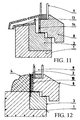
- Fig. 1 represents a cross section of one side of the window structure and its placing into the constructional exterior structure 1 in such a way that the termination batten 2 is a non-divisible part of the frame 3 of the window or fixed part of a constructional exterior structure 1.
- the above mentioned termination batten overlaps the structure of the wing frame 8 as well as the panel part 9 made by insulation prefabricated insulation double glazing in all described examples of the execution of the invention however any other known materials may be used for example advantageous prefabricated insulation triple glazing and so on.
- the termination batten 2 is completely overlapped by constructional exterior structure 1 from its external part.
- the constructional exterior structure is created by one or by a combination of more common structural elements for the purposes of this description.
- These elements may be for example thermal insulation with a plaster or cladding, masonry with a plaster or cladding, concrete, ecru masonry, poured structural materials as for example concrete, aggregate, wood, steel, concrete supporting and non-supporting structures, coatings and paints, claddings, wood profiles of the window shutters and the like; also the window sill, which is simultaneously adapted to the structural design of the window pursuant to the invention, is also being considered to be a part of constructional exterior structure for the purposes of the description of this invention.
- the shape of profiles of the frame and wings has been executed only in general which means without details as for example ironwork, sealing and other parameters which may be different pursuant to the specific manufacturing, aesthetic and other requirements and these various execution do not influence the nature of the invention.
- Fig. 2 there is an arrangement represented in the cross section of the part of the structure when in constructional exterior structure 1 there is a window frame 3 inserted on the circumferential surface of which there fits the termination batten 2 in the shape of triangle which is simultaneously inserted in circumferential surfaces of the view batten 7 making a part of constructional exterior structure 1.
- Internal circumferential surface of view batten 7 protrudes also the window frame 8 as well as a part of surface of the panel 9 consisting of insulation prefabricated double glazing from the inside view.
- Fig. 3 represents the similar structural arrangement as having been described in a clarification of the example of the invention execution to Fig. 2 when the view batten 7 is connected to the constructional exterior structure which batten simultaneously protrudes an upper part of the inserted window frame 3 and which covers the frame structure 8 of the wing with a panel 9 from the outside view.
- the view batten 7 may be also made as a part of window frame 3.
- Fig. 4 there is an example of execution represented where the constructional exterior structure 1 is equipped with an inserted window frame 3 from the internal side on the circumferential surface of which there is a termination batten 2 placed.
- the window frame 8 is equipped with a panel 9 equipped with a front batten 10 fixing also the panel 9 in the wing frame 8 on the surface of the near side of the constructional exterior structure.
- Fig. 5 represents a cross section of the window structure part where the constructional exterior structure 1 is equipped with a frame 3 on the internal side on the circumferential surface of which there is a window blind batten 11 set.
- the bearing wing frame 8 with a panel 9 is concurrently equipped with a sealing 12 on the surface of the near side of the constructional exterior structure 1 or as the case may be window blind batten 11 .
- FIG. 6 there is an example of execution represented which is similar to the example already described in Fig. 1 where in the constructional exterior structure 1 there is a window frame 3 placed on the internal circumferential surface of which there is a triangle termination batten 2 placed.
- the window frame 8 with a panel 9 is equipped with a sealing 12 on the surface near to the window frame 3 and to the termination angle piece 2 while the sealing 12 and window frame 8 protrude the upper surface of constructional exterior structure 1 and termination area 2 from the external view.
- Fig. 7 represents an execution in the cross section of the part of the window structure when the upper surface of constructional exterior structure 1 and thereby inserted window frame 3 is equipped with a connected window sill 13 .
- the window frame 8 with a panel 9 is equipped with a weatherboarding 14 on the surface near to the window frame 3, which protrudes the window sill 13 by its free end.
- Fig. 8 represents an execution where there is a window sill 13 placed on the upper surface of constructional exterior structure 1 and on a part of upper frame surface 3 of the window the internal end of which window sill interferes under the wing frame 8 equipped with a panel 9 and front batten 10.
- Fig. 9 there is an example of execution represented where there is a window frame 3 placed in the constructional exterior structure 1 on the upper circumferential surface of which frame there is a withdrawal duct 15 with a drainage 16 placed.
- the withdrawal duct 15 and constructional exterior structure 1 are thereby equipped with a window sill 13 on the upper circumferential surface being equipped by a sealing not designated here by any relational mark on the surface fitting closely to the panel 9.
- the window frame 8 with a panel 9 is equipped with a weatherboarding 14 on the surface near to the withdrawal duct 15.
- Fig. 10 represents an example of execution where in the constructional exterior structure 1 there is a window frame 3 placed and on the upper surfaces of which there is a double window sill 13 placed which sill is equipped with a sealing 12 on the bearing surface of the frame panel 9 of the wing frame 8.
- Fig. 11 represents an arrangement in the cross section of the window part where on the constructional exterior structure 1 with a placed window frame 3 there is a double window sill 13 placed with a partially open upper surface.
- the wing frame 8 with a panel 9 is equipped with a connected weatherboarding 14 on the surface near to the window frame 3 and to the double window sill 13 the free end of which weatherboarding interferes to the open upper surface of the double window sill 13 .
- Fig. 12 there is an example of execution represented where the constructional exterior structure 1 is equipped with an inserted window frame 3 with a placed termination batten 2 overlapped by a structural profile 4.
- the window frame 8 is equipped with a panel 9 fixed to the front batten 10 in a wing frame 8.
- Fig. 13 represents a cross section of one side of the window structure and its placing into the constructional exterior structure 1 made in such a way that the termination batten 2 overlapping the wing frame structure 8 and part of the panel 9 is a non-divisible part of the window frame 3.
- the termination batten 2 is completely covered by covering profile 4 from its external part. At the same time the covering profile 4 overlaps a part of frame 3.
- Fig. 14 there is an arrangement represented in a cross section of the part of structure where in a constructional exterior structure 1 there is a window frame 3 placed on the internal circumferential surface of which there fits the termination batten 2 in a shape of triangle which overlaps a window frame 8 with a panel 9 where the termination batten 2 is overlapped from its external and front side by covering profile 4.
- Fig. 15 represents a cross section of the part of a window structure where the constructional exterior structure 1 is equipped with a frame 3 on the internal circumferential surface of which there is a covering profile 4 with a window blind guide placed.
- the wing frame 8 is with a panel 9, which is fixed by the front batten 10.
- Fig. 16 there is an example of execution represented which example is similar to the example having been described in Fig. 13 where in the constructional exterior structure 1 there is a window frame 3 placed on the internal circumferential surface if which frame there is a triangle termination batten 2 placed which batten is overlapped by the covering profile 4.
- the wing frame 8 with a panel 9 is equipped with a front batten 10 on the surface near to the window frame 3 and to the termination angle piece 2 while the front batten 10 is not completely covered by a termination batten 2.
- Fig. 17 represents an arrangement in a cross section of a part of the window where there is a covering profile 4 placed on constructional exterior structure 1 with a placed window frame 3 which profile overlaps a termination batten 2 from its external part which batten fits partially to the wing panel 9 and partially o the front batten 10 fixing the panel 9 which has been placed in the wing frame 8 .
- Fig. 18 represents an arrangement in a cross section of a part of the window where there is a covering profile placed on constructional exterior structure 1 with a placed window frame 3 which covering profile consists of two materially different parts 4a, 4b (in a described execution of the invention there is for example a combination of polystyrene/ceramic cladding used) and which overlaps the termination batten 2 from its external part which batten is covered by sealing 12 from its front side which fits to the wing frame 8 at which the front batten is an integral part of. Then a filling 9 is inserted into the wing frame 8 via the guide 11. The wing frame 8 is with a filling 9, which is fixed by a front batten 10.
- Fig. 19 represents an example of the execution where in the constructional exterior structure 1 there is a window frame 3 placed and on its upper surfaces there is a double window sill 13 placed which sill is equipped with a weatherboarding 14 on the bearing surface of the wing frame 8 panel 9.
- Fig. 20 represents a cross section of one side of the window structure arranged in such a way that the termination batten 2 with a sealing 12 is a non-divisible part of the window frame 3 which batten overlaps the part of the wing frame 8 structure, front batten 10 and part of panel 9 .
- the part of termination batten 2 and of a window frame 3 are covered by sunk profile 5 from its external part.
- Fig. 21 represents a cross section of one side of the window structure in such a way that the termination batten 2 is a non-divisible part of the window frame 3 which batten is modified to the outlet to the window sill 13 by its shape.
- the termination batten 2 overlaps the part of the frame structure of the wing frame 8, panel 9 and front batten 10.
- the front batten 10 is fit with a weatherboarding 14.
- the part of a termination batten 2 and of window frame 3 are overlapped by a sunk profile 5 from their external side.
- Fig. 22 represents a cross section of one side of the window structure made in such a way that the termination batten 2 with a sealing 12 is a non-divisible part of the window frame 3 which batten overlaps the part of the wing frame 8 structure, front batten 10 and part of panel 9.
- the part of termination batten 2 and of a window frame 3 are covered by sunk profile 5 from its external part.
- the window in the described drawing is represented in its built in conditions in a constructional structure 1 with a cover 7.
- Fig. 23 represents a cross section of one side of the window structure made in such a way that the termination batten 2 with a sealing 12 is a non-divisible part of the window frame 3 which batten overlaps the part of the wing frame 8 structure, front batten 10 and part of panel 9.
- the part of termination batten 2 and of a window frame 3 are covered by sunk profile 5 from its external part.
- the structure of the window/door and its building into the constructional exterior structure pursuant to the invention is utilizable almost in all common structural buildings without limitation where when compared with a present windows/doors it increases thermal resistance of the opening panels, it reduces costs for their maintenance and simultaneously extends their life time, it increases the security of the building against entry via opening panels, it reduces costs for manufacture of opening panels and thereby civil costs in appropriate part, it increases energetic savings or as the case may be savings achieved via opening panels installed pursuant to the invention, it makes a different architectural and aesthetic designs possible, it simplifies an execution of opening panel as a new architectural design with antifire effects. '
Landscapes
- Engineering & Computer Science (AREA)
- Civil Engineering (AREA)
- Structural Engineering (AREA)
- Specific Sealing Or Ventilating Devices For Doors And Windows (AREA)
- Door And Window Frames Mounted To Openings (AREA)
Applications Claiming Priority (6)
| Application Number | Priority Date | Filing Date | Title |
|---|---|---|---|
| CZ20033028A CZ20033028A3 (cs) | 2003-11-07 | 2003-11-07 | Konstrukce okna a nebo dveří a jejich umístění ve stavební exteriérové konstrukci |
| CZ20033028 | 2003-11-07 | ||
| CZ20040146 | 2004-01-28 | ||
| CZ2004146A CZ2004146A3 (cs) | 2004-01-28 | 2004-01-28 | Konstrukce okna a/nebo dveří a jejich umístění ve stavební exteriérové konstrukci |
| CZ2004192A CZ2004192A3 (cs) | 2004-02-04 | 2004-02-04 | Konstrukce okna a/nebo dveří |
| CZ20040192 | 2004-02-04 |
Publications (2)
| Publication Number | Publication Date |
|---|---|
| EP1529917A2 true EP1529917A2 (de) | 2005-05-11 |
| EP1529917A3 EP1529917A3 (de) | 2006-08-30 |
Family
ID=34437461
Family Applications (1)
| Application Number | Title | Priority Date | Filing Date |
|---|---|---|---|
| EP04466029A Withdrawn EP1529917A3 (de) | 2003-11-07 | 2004-11-05 | Fenster oder Türkonstruktion und sein Einbauverfahren in einem Gebäude |
Country Status (1)
| Country | Link |
|---|---|
| EP (1) | EP1529917A3 (de) |
Cited By (3)
| Publication number | Priority date | Publication date | Assignee | Title |
|---|---|---|---|---|
| EP1719868A1 (de) * | 2005-04-07 | 2006-11-08 | Gegg Götz | Fenster oder Tür |
| EP2105567A1 (de) * | 2008-03-26 | 2009-09-30 | VKR Holding A/S | Fensterbaugruppe mit Abdeckplattenanordnung zur Abdeckung der Fensteröffnung |
| CN104763281A (zh) * | 2015-03-30 | 2015-07-08 | 多维联合集团有限公司 | 一种窗体包边节点结构及其施工方法 |
Citations (8)
| Publication number | Priority date | Publication date | Assignee | Title |
|---|---|---|---|---|
| DE2605844A1 (de) * | 1976-02-13 | 1977-08-18 | Heinrich Schultes | Schallschutzfenster |
| EP0823530A2 (de) * | 1996-08-08 | 1998-02-11 | Saint-Gobain Vitrage | Aussenwand mit hoher Wärmeisolierung |
| WO1998017887A1 (de) * | 1996-10-23 | 1998-04-30 | Ruepp Beratungen | Fenster-system |
| DE29819948U1 (de) * | 1998-11-07 | 1999-05-12 | Caldonazzi Richard Ing | Fenster- oder Türöffnung in einer Gebäudewand |
| DE20008697U1 (de) * | 1999-11-10 | 2000-08-03 | Fleck Erwin | Profil |
| DE19910320A1 (de) * | 1999-03-09 | 2000-10-12 | Holzbau Kaustraeter Gmbh | Fenster- oder Türrahmen |
| AT4382U1 (de) * | 2000-10-10 | 2001-06-25 | Guenter Reautschnig | Fenster |
| DE10125902A1 (de) * | 2000-06-07 | 2002-01-31 | Josko Fenster Und Tueren Gmbh | Fenster- oder Türkonstruktion |
-
2004
- 2004-11-05 EP EP04466029A patent/EP1529917A3/de not_active Withdrawn
Patent Citations (8)
| Publication number | Priority date | Publication date | Assignee | Title |
|---|---|---|---|---|
| DE2605844A1 (de) * | 1976-02-13 | 1977-08-18 | Heinrich Schultes | Schallschutzfenster |
| EP0823530A2 (de) * | 1996-08-08 | 1998-02-11 | Saint-Gobain Vitrage | Aussenwand mit hoher Wärmeisolierung |
| WO1998017887A1 (de) * | 1996-10-23 | 1998-04-30 | Ruepp Beratungen | Fenster-system |
| DE29819948U1 (de) * | 1998-11-07 | 1999-05-12 | Caldonazzi Richard Ing | Fenster- oder Türöffnung in einer Gebäudewand |
| DE19910320A1 (de) * | 1999-03-09 | 2000-10-12 | Holzbau Kaustraeter Gmbh | Fenster- oder Türrahmen |
| DE20008697U1 (de) * | 1999-11-10 | 2000-08-03 | Fleck Erwin | Profil |
| DE10125902A1 (de) * | 2000-06-07 | 2002-01-31 | Josko Fenster Und Tueren Gmbh | Fenster- oder Türkonstruktion |
| AT4382U1 (de) * | 2000-10-10 | 2001-06-25 | Guenter Reautschnig | Fenster |
Cited By (3)
| Publication number | Priority date | Publication date | Assignee | Title |
|---|---|---|---|---|
| EP1719868A1 (de) * | 2005-04-07 | 2006-11-08 | Gegg Götz | Fenster oder Tür |
| EP2105567A1 (de) * | 2008-03-26 | 2009-09-30 | VKR Holding A/S | Fensterbaugruppe mit Abdeckplattenanordnung zur Abdeckung der Fensteröffnung |
| CN104763281A (zh) * | 2015-03-30 | 2015-07-08 | 多维联合集团有限公司 | 一种窗体包边节点结构及其施工方法 |
Also Published As
| Publication number | Publication date |
|---|---|
| EP1529917A3 (de) | 2006-08-30 |
Similar Documents
| Publication | Publication Date | Title |
|---|---|---|
| EP2161402B2 (de) | Vorgefertigte Tür- oder Fensterrahmen-Einheit mit isolierender Randeinfassung | |
| CZ300321B6 (cs) | Protipožární dvere | |
| ITBZ20110056A1 (it) | Telai per serramenti in materiale termoplastico saldabile, rivestibili con materiali diversi | |
| EP1529917A2 (de) | Fenster oder Türkonstruktion und sein Einbauverfahren in einem Gebäude | |
| Krippner et al. | Basics Facade Apertures | |
| WO2017068408A1 (en) | Frame construction profile for closure of an opening in a construction wall, frames made of such profiles, windows or doors having such frames and a method of fastening such windows or doors, in insulating section of the walls | |
| US20160108658A1 (en) | Invisible window frames | |
| EP1601839B1 (de) | Erweiterung an einem bestehenden Gebäude | |
| KR200417783Y1 (ko) | 발코니 확장용 창호 구조물 | |
| WO1989008767A1 (en) | Improvements in the installation of roller shutters | |
| RU2272115C2 (ru) | Окно или дверь | |
| KR100478433B1 (ko) | 창호의 가틀 조립구조 | |
| GB2374096A (en) | Facade for remedial support lintel | |
| AU714654B2 (en) | Building component | |
| EP0566562B1 (de) | Struktur paneel und verbindungsstück zwischen solchen paneelen und verfahren zur herstellung und verwendung | |
| CN220645643U (zh) | 一种新型飘窗结构及建筑 | |
| CN217106652U (zh) | 一种复合型古建门窗 | |
| Hochberg et al. | Open I close: windows, doors, gates, loggias, filters | |
| RU74151U1 (ru) | Теплоизоляционное обрамление окон | |
| EP3748116B1 (de) | Tür oder fenster | |
| Sutherland | Façade performance | |
| WO2021088312A1 (zh) | 一种应用于建筑物的墙单元及组合式墙体 | |
| DE19711149C1 (de) | Fenster- und Außentüreinsätze mit vorgefertigtem Rolladenaufnahmekasten für Elektro-Rolläden aus Beton, starren Kunststoffen, Verbundgußmassen und Verbundwerkstoffen, insbesondere für den Rohbau von Wohnhäusern | |
| KR200269611Y1 (ko) | 창호의 시공방법 및 가틀 조립구조 | |
| DE19704762C1 (de) | Fenster- und Außentüreinsätze mit vorgefertigtem Rolladenaufnahmekasten und Gurtrollerschacht aus Beton, starren Kunststoffen und Verbundgußmassen, insbesondere für den Rohbau von Wohnhäusern |
Legal Events
| Date | Code | Title | Description |
|---|---|---|---|
| PUAI | Public reference made under article 153(3) epc to a published international application that has entered the european phase |
Free format text: ORIGINAL CODE: 0009012 |
|
| AK | Designated contracting states |
Kind code of ref document: A2 Designated state(s): AT BE BG CH CY CZ DE DK EE ES FI FR GB GR HU IE IS IT LI LU MC NL PL PT RO SE SI SK TR |
|
| AX | Request for extension of the european patent |
Extension state: AL HR LT LV MK YU |
|
| 17P | Request for examination filed |
Effective date: 20051013 |
|
| PUAL | Search report despatched |
Free format text: ORIGINAL CODE: 0009013 |
|
| AK | Designated contracting states |
Kind code of ref document: A3 Designated state(s): AT BE BG CH CY CZ DE DK EE ES FI FR GB GR HU IE IS IT LI LU MC NL PL PT RO SE SI SK TR |
|
| AX | Request for extension of the european patent |
Extension state: AL HR LT LV MK YU |
|
| AKX | Designation fees paid |
Designated state(s): AT BE BG CH CY CZ DE DK EE ES FI FR GB GR HU IE IS IT LI LU MC NL PL PT RO SE SI SK TR |
|
| STAA | Information on the status of an ep patent application or granted ep patent |
Free format text: STATUS: THE APPLICATION IS DEEMED TO BE WITHDRAWN |
|
| 18D | Application deemed to be withdrawn |
Effective date: 20070310 |