EP1529907B1 - Vorhängeschloss mit zwei getrennten unabhängigen Schliesssystemen - Google Patents
Vorhängeschloss mit zwei getrennten unabhängigen Schliesssystemen Download PDFInfo
- Publication number
- EP1529907B1 EP1529907B1 EP20040256580 EP04256580A EP1529907B1 EP 1529907 B1 EP1529907 B1 EP 1529907B1 EP 20040256580 EP20040256580 EP 20040256580 EP 04256580 A EP04256580 A EP 04256580A EP 1529907 B1 EP1529907 B1 EP 1529907B1
- Authority
- EP
- European Patent Office
- Prior art keywords
- shackle
- padlock
- movement
- zone
- housing
- Prior art date
- Legal status (The legal status is an assumption and is not a legal conclusion. Google has not performed a legal analysis and makes no representation as to the accuracy of the status listed.)
- Expired - Lifetime
Links
- 238000010276 construction Methods 0.000 claims description 57
- 230000000903 blocking effect Effects 0.000 claims description 13
- 230000009977 dual effect Effects 0.000 description 33
- 238000007789 sealing Methods 0.000 description 11
- 230000003213 activating effect Effects 0.000 description 6
- 230000002093 peripheral effect Effects 0.000 description 5
- 238000011179 visual inspection Methods 0.000 description 4
- 230000002860 competitive effect Effects 0.000 description 3
- 238000011109 contamination Methods 0.000 description 3
- 230000007613 environmental effect Effects 0.000 description 3
- 230000000007 visual effect Effects 0.000 description 3
- 101000793686 Homo sapiens Azurocidin Proteins 0.000 description 2
- 230000004323 axial length Effects 0.000 description 2
- 230000015556 catabolic process Effects 0.000 description 2
- 239000000356 contaminant Substances 0.000 description 2
- 238000006731 degradation reaction Methods 0.000 description 2
- 239000012467 final product Substances 0.000 description 2
- 238000003780 insertion Methods 0.000 description 2
- 230000037431 insertion Effects 0.000 description 2
- 238000007689 inspection Methods 0.000 description 2
- 230000007774 longterm Effects 0.000 description 2
- 230000002411 adverse Effects 0.000 description 1
- 238000009937 brining Methods 0.000 description 1
- 230000007812 deficiency Effects 0.000 description 1
- 230000000694 effects Effects 0.000 description 1
- 230000002452 interceptive effect Effects 0.000 description 1
- 238000004519 manufacturing process Methods 0.000 description 1
- 239000000463 material Substances 0.000 description 1
- 238000000034 method Methods 0.000 description 1
- 230000037361 pathway Effects 0.000 description 1
- 239000000047 product Substances 0.000 description 1
Images

Classifications
-
- E—FIXED CONSTRUCTIONS
- E05—LOCKS; KEYS; WINDOW OR DOOR FITTINGS; SAFES
- E05B—LOCKS; ACCESSORIES THEREFOR; HANDCUFFS
- E05B67/00—Padlocks; Details thereof
- E05B67/06—Shackles; Arrangement of the shackle
- E05B67/08—Padlocks with shackles hinged on the case
- E05B67/10—Padlocks with shackles hinged on the case with devices for securing the free end of the shackle
-
- E—FIXED CONSTRUCTIONS
- E05—LOCKS; KEYS; WINDOW OR DOOR FITTINGS; SAFES
- E05B—LOCKS; ACCESSORIES THEREFOR; HANDCUFFS
- E05B35/00—Locks for use with special keys or a plurality of keys ; keys therefor
- E05B35/08—Locks for use with special keys or a plurality of keys ; keys therefor operable by a plurality of keys
- E05B35/10—Locks for use with special keys or a plurality of keys ; keys therefor operable by a plurality of keys with master and pass keys
- E05B35/105—Locks allowing opening by official authorities, e.g. master key opening of luggage locks by customs officials
-
- E—FIXED CONSTRUCTIONS
- E05—LOCKS; KEYS; WINDOW OR DOOR FITTINGS; SAFES
- E05B—LOCKS; ACCESSORIES THEREFOR; HANDCUFFS
- E05B37/00—Permutation or combination locks; Puzzle locks
- E05B37/02—Permutation or combination locks; Puzzle locks with tumbler discs or rings arranged on a single axis, each disc being adjustable independently of the others
- E05B37/025—Permutation or combination locks; Puzzle locks with tumbler discs or rings arranged on a single axis, each disc being adjustable independently of the others in padlocks
-
- E—FIXED CONSTRUCTIONS
- E05—LOCKS; KEYS; WINDOW OR DOOR FITTINGS; SAFES
- E05B—LOCKS; ACCESSORIES THEREFOR; HANDCUFFS
- E05B37/00—Permutation or combination locks; Puzzle locks
- E05B37/0031—Locks with both permutation and key actuation
- E05B37/0034—Locks with both permutation and key actuation actuated by either
-
- E—FIXED CONSTRUCTIONS
- E05—LOCKS; KEYS; WINDOW OR DOOR FITTINGS; SAFES
- E05B—LOCKS; ACCESSORIES THEREFOR; HANDCUFFS
- E05B37/00—Permutation or combination locks; Puzzle locks
- E05B37/0048—Permutation or combination locks; Puzzle locks with changeable combination
- E05B37/0058—Permutation or combination locks; Puzzle locks with changeable combination by axial disengagement between hub and rim of tumbler discs or rings
-
- E—FIXED CONSTRUCTIONS
- E05—LOCKS; KEYS; WINDOW OR DOOR FITTINGS; SAFES
- E05B—LOCKS; ACCESSORIES THEREFOR; HANDCUFFS
- E05B67/00—Padlocks; Details thereof
- E05B67/06—Shackles; Arrangement of the shackle
- E05B67/22—Padlocks with sliding shackles, with or without rotary or pivotal movement
-
- Y—GENERAL TAGGING OF NEW TECHNOLOGICAL DEVELOPMENTS; GENERAL TAGGING OF CROSS-SECTIONAL TECHNOLOGIES SPANNING OVER SEVERAL SECTIONS OF THE IPC; TECHNICAL SUBJECTS COVERED BY FORMER USPC CROSS-REFERENCE ART COLLECTIONS [XRACs] AND DIGESTS
- Y10—TECHNICAL SUBJECTS COVERED BY FORMER USPC
- Y10T—TECHNICAL SUBJECTS COVERED BY FORMER US CLASSIFICATION
- Y10T70/00—Locks
- Y10T70/40—Portable
- Y10T70/413—Padlocks
- Y10T70/415—Combination and/or key-controlled
-
- Y—GENERAL TAGGING OF NEW TECHNOLOGICAL DEVELOPMENTS; GENERAL TAGGING OF CROSS-SECTIONAL TECHNOLOGIES SPANNING OVER SEVERAL SECTIONS OF THE IPC; TECHNICAL SUBJECTS COVERED BY FORMER USPC CROSS-REFERENCE ART COLLECTIONS [XRACs] AND DIGESTS
- Y10—TECHNICAL SUBJECTS COVERED BY FORMER USPC
- Y10T—TECHNICAL SUBJECTS COVERED BY FORMER US CLASSIFICATION
- Y10T70/00—Locks
- Y10T70/40—Portable
- Y10T70/413—Padlocks
- Y10T70/417—Combination-controlled
- Y10T70/422—Rigid shackle
- Y10T70/424—Sliding
-
- Y—GENERAL TAGGING OF NEW TECHNOLOGICAL DEVELOPMENTS; GENERAL TAGGING OF CROSS-SECTIONAL TECHNOLOGIES SPANNING OVER SEVERAL SECTIONS OF THE IPC; TECHNICAL SUBJECTS COVERED BY FORMER USPC CROSS-REFERENCE ART COLLECTIONS [XRACs] AND DIGESTS
- Y10—TECHNICAL SUBJECTS COVERED BY FORMER USPC
- Y10T—TECHNICAL SUBJECTS COVERED BY FORMER US CLASSIFICATION
- Y10T70/00—Locks
- Y10T70/70—Operating mechanism
- Y10T70/7141—Combination and key
-
- Y—GENERAL TAGGING OF NEW TECHNOLOGICAL DEVELOPMENTS; GENERAL TAGGING OF CROSS-SECTIONAL TECHNOLOGIES SPANNING OVER SEVERAL SECTIONS OF THE IPC; TECHNICAL SUBJECTS COVERED BY FORMER USPC CROSS-REFERENCE ART COLLECTIONS [XRACs] AND DIGESTS
- Y10—TECHNICAL SUBJECTS COVERED BY FORMER USPC
- Y10T—TECHNICAL SUBJECTS COVERED BY FORMER US CLASSIFICATION
- Y10T70/00—Locks
- Y10T70/70—Operating mechanism
- Y10T70/7153—Combination
- Y10T70/7322—Permutation
- Y10T70/7345—Removable change element
Definitions
- This invention relates to padlocks and lock systems and, more particularly, to padlocks constructed to provide two separate an independent modes by which the padlock can be opened and closed.
- combination lock which employs a plurality of rotatable independent dials, each of which forms one of the indicia, usually numerals or letters, which comprise the combination for releasing the lock.
- the combination lock has one mode or position in which the user is able to set or reset the desired combination sequence.
- key operated locks do not suffer from the difficulty of having the combination changed or altered without the user's knowledge, users are frequently incapable of using key operated locks, due to the key being lost or misplaced. As a result, prior art key operated locks are also frequently discarded due to the user's inability to find a particular key for operating the lock.
- all luggage must be scanned or inspected to prevent the transportation of potentially dangerous items or products which are deemed to be undesirable.
- the inspectors have the authority to open the luggage for visual inspection, including physically breaking any lock which may be on the luggage.
- US 2003/0000 264 A1 discloses a padlock constructed for providing two separate and independent locking means in a single, integrated construction, with a first locking assembly being controlled by a combination and a second locking assembly being key controlled.
- the padlock essentially comprises a housing; a generally J-shaped shackle; a plurality of dials mounted in a dial receiving zone of the housing and a key controlled lock assembly mounted in the housing and comprising a cylinder assembly.
- the Shackle will be movable to an unlocked position by establishing the correct combination using the dials, or by rotating the cylinder assembly after insertion of a designated key member into the key receiving slot.
- the goal of the present invention is to provide an alternative arrangement of two separate and indepedent locking systems in a single padlock.
- a single housing and shackle assembly are employed and constructed for enabling the shackle to be released from locked engagement with the housing using either a rotatable dial combination construction or a key activating tumbler construction. In this way, a dual locking and releasing padlock is achieved.
- a generally conventional J-shaped shackle is employed with one portion of the housing cooperatively associated with the longer leg of the shackle.
- this portion of the housing is also constructed with rotatable, combination defining dials which control the axial movement of the longer leg of the shackle.
- axial movement of the shackle in the housing is completely controlled by the rotatable, combination defining dials, enabling the locking and releasing of the shackle relative to the housing by employing the known combination.
- a plurality of tumbler sleeves is thereby rotationally mounted to the long leg of the shackle and the dials are peripherally surrounding a respective tumbler sleeve.
- the key activating portion of the housing is constructed for lockingly engaging and releasing the short leg of the shackle.
- a tumbler and rotatable chamber lock assembly which is responsive to the cuts on a key for positioning the tumblers to be properly aligned for enabling the chamber to be rotatable, in contrast to the state of the art, controlled movement of a shackle engaging cavity is achieved, which either lockingly engages the shackle to the housing or releases the shackle for rotatable movement relative to the housing.
- the user is capable of employing either of two separate and independent shackle controlling locking systems for releasing the shackle from locked engagement with the housing whenever release is desired.
- the control system for one of the locking modes is not available, the second mode can be employed for completely operating the padlock in the desired manner.
- a Master Key is created which is able to open the key controlled section of all dual mode padlocks.
- the Customs officer or security personnel is able to open the dual locking mode padlocks by employing the Master Key, which is provided to all such individuals. In this way, physically breaking a lock is totally eliminated and, once visual inspection has been completed, the dual locking mode pad-locks would be replaced on the luggage and locked in position, in order to assure that the contents remains secure throughout the remainder of the trip.
- the padlocks of the present invention are constructed with the interior chambers virtually sealed from the ambient surroundings, thereby preventing unwanted contamination from entering the interior of the padlock and the rotating component thereof. In this way, prior art degradation and interference of the lock operation by contamination is virtually eliminated.
- a minimum number of components are employed in combination with the housing and the movable shackle, in order to provide the desired unique, dual mode padlock constructions of the present invention.
- the shackle and housing only the plurality of rotating dials, plurality of tumblers sleeves, key operated tumblers and rotatable chamber are required to provide the dual mode padlock constructions of this invention.
- the present invention achieves a dual mode padlock using a minimum number of independent components, each of which is capable of being quickly assembled into the final product.
- a construction is attained which is capable of being manufactured at a competitive price, while providing a high quality, highly effective dual mode padlock which virtually eliminates any degradation due to exposure to environmental contamination.
- the invention accordingly comprises an article of manufacture assessing the features, properties, and the relation of elements which will be exemplified in the article hereinafter described, and the scope of the invention as defined by the claims.
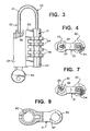
- FIGURES 1-26 the construction and operation of two alternate embodiments of dual mode padlock 20 of the present invention can best be understood.
- the preferred two, alternate embodiment of the present invention are fully disclosed.
- this disclosure is provided for exemplary purposes only and, since the present invention can be implemented using further alternate constructions, it is intended that these alternate constructions are within the scope of the present invention.
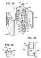
- FIGURES 1-19 one preferred embodiment of dual mode padlock 20 of the present invention is depicted using a minimum of principal components, thereby achieving a dual mode padlock, while also substantially reducing the complexity found in most prior art padlocks.
- the present invention provides a highly effective, commercially desirable construction which is capable of being produced at a competitive cost, while also providing the unique attributes of the present invention and all of the locking and theft deterrent features typically incorporated in prior art padlocks.
- the two principal components which form the dual mode padlock 20 comprise central housing 21 and shackle 22, with central housing 21 incorporating combination controlled locking section 23 formed on one side thereof and key controlled locking section 24 formed on the opposed side thereof.
- the components required for forming and operating combination controlled locking section 23, as well as the components required for forming and operating key controlled locking section 24 are all detailed below.
- the cooperative engagement of shackle 22 with housing 21 is employed.
- shackle 22 comprises a conventional J-shape incorporating short leg 25 which has a terminating end 26, and long leg 27 having terminating end portion or section 28.
- shackle 22 is in its locked and fully engaged position when a major portion of long leg 27 is contained within housing 21 and terminating end 26 of short leg 25 is engaged within locking collar 29.
- terminating end 26 of short leg 25 must be released or disengaged from locking collar 29.
- short leg 25 is engaged or released from locking collar 29 by activating one of the two locking sections formed in housing 21.
- combination controlled locking section 23 By employing combination controlled locking section 23, and properly inputting the correct preset combination, the long leg 27 of shackle 22 is released and is able to move longitudinally or axially relative to housing 21. This longitudinal or axial movement enables terminating end 26 of short leg 25 to be axially removed from locking collar 29 resulting in the opening of dual mode padlock 20, as shown in FIGURE 5 .
- locking collar 29 is able to be arcuately pivoted, preferably through an angular distance of about 90°, positioning slot 30 formed in locking collar 29 to a location which allows shackle 22 to be arcuately pivotable relative to housing 21, enabling terminating end 26 of short leg 25 to be moved out of engagement within locking collar 29, as shown in FIGURES 6 and 7 .
- shackle 22 is released from locked engagement with collar 29, enabling the removal of padlock 20 from the items to which it had been secured or, alternatively, enabling items to be securely engaged therewith.
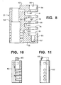
- combination controlled locking section 23 incorporates four separate and independent tumbler sleeves 33 and four separate and independent rotatable dials 34. By employing these components, along with housing 21 and shackle 22, an easily produced, highly effective combination controlled locking section is realized.
- Each tumbler sleeve 33 comprises a generally cylindrical shape incorporating a single locking fin 35 radially extending from outer, circular-shaped surface 36.
- each tumbler sleeve 33 also comprises an inside, circular-shaped surface 37 which is coaxially aligned with outside surface 36.
- the diameter of inside surface 37 of tumbler sleeve 33 is constructed to enable each tumbler sleeve 33 to freely pivot about the outer surface of shackle 22.
- Each dial 34 is constructed for peripherally surrounding and cooperating with a tumbler sleeve 33.
- each dial 34 comprises two separate and distinct, circular-shaped inside surfaces 38 and 39.
- Side surface 38 comprises a diameter slightly greater than the diameter of outside surface 36 of tumbler sleeve 33, in order to enable tumbler sleeve 33 and dial 34 to cooperate with each other while being independently rotationally movable about 22.
- each dial 34 comprises a plurality of slots 40 formed in inside surface 38, with each slot being constructed for receiving and retaining radially extending fin 35 of tumbler sleeve 33. In this way, whenever radially extending fin 35 is mounted in a slot 40 of dial 34, tumbler sleeve 33 and dial 34 are in interlocked engagement, causing both members to rotate together about shackle 22.
- the number of slots 40 formed in dial 34 corresponds to the number of separate and distinct indicia formed on the outer surface of dial 34.
- ten indicia are employed on the outside surface of dial 34 and ten slots 40 are formed in surface 38.
- dial 34 Inside surface 39 of dial 34 comprises a circular shape formed by a diameter which is aligned with the axis of surface 38, but is greater than the length of fin 35. In this way, when fin 35 is disengaged from slot 40 of dial 34, dial 34 is able to rotate about shackle 22 independently of tumbler sleeve 33. Each tumbler sleeve 33 is rotationally mounted to leg 27 of shackle 22, with each tumbler sleeve having a dial 34 rotationally associated therewith.
- each dial 34 has a plurality of indicia formed on the outer peripheral surface thereof, each of which represents one component of the combination for positioning tumbler sleeves 33 in the requisite location for releasing shackle 22.
- indicia any desired indicia can be employed, numerals or letters are typically employed on prior art constructions.
- each dial 34 comprises an outer surface 44 on which ten panels 45 are formed with slots separating each panel 45.
- one numeral ranging from 0, 1, 2, 3, 4, 5, 6, 7, 8 and 9 is formed on each panel 45. The numeral in each panel 45 of each dial 24 is then employed to define the combination for padlock 20.
- leg 27 of shackle 22 incorporates ribs 48 and 49 formed on the outer surface thereof and a locking ring receiving slot 50 formed directly adjacent terminating end section 28 of leg 27 of shackle 22.
- the axial distance between ribs 48 and 49 and slot 50 is constructed for being substantially equivalent to the axial length required for enabling locking ring 46, when mounted in slot 50, to retain the four tumbler sleeves 33 on leg 27 of shackle 22, with each tumbler sleeves 33 being capable of independent rotational movement, while substantially eliminating any axial movement thereof.
- tumbler sleeves 33 are able to provide the desired locking and unlocking function, while achieving this result in an easily manufactured and easily assembled construction.
- a visual indicator of the proper orientation for each numeral or letter of each panel 45 of each dial 34 is also provided by incorporating on housing 21 a position orientating line. This line enables the user to visually position each numeral in the proper location for a pre-set combination.
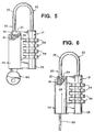
- housing 21 comprises a single piece construction, within which various cavities, bores, and receiving zones are formed for enabling the dual, independent, locking systems to operate.
- housing 21 comprises a top surface 50, a bottom surface 51, a front panel 52, a rear panel 53, and two side panels 54 and 55.
- combination controlled locking section 23 of housing 21 incorporates a central, elongated bore 56 which extends through section 23 from top surface 50 to bottom surface 51.
- bore 56 comprises portal 68, formed with top surface 50.
- bore 56 comprises three separate diameters, forming three separate and independent coaxial zones 57, 58, and 59.
- Zone 57 comprises the lowermost zone of bore 56, and comprises a diameter slightly greater than the diameter of shackle 22. In this way, terminating end section 28 of leg 27 of shackle 22 is capable of axial movement in zone 57, while also preventing any other components mounted to leg 33 of shackle 22 from entering zone 57.
- Zone 58 comprises the intermediate zone of bore 56 and has a diameter slightly greater than the outside diameter of tumbler sleeves 33. In this way, tumbler sleeves 33 are capable of axial movement through zone 58 of central bore 56.
- zone 58 also comprises an elongated slot or channel 60 formed along one wall of zone 58, providing the release position for each radially extending fin 35 of each tumbler sleeve 33.
- shackle 22 when each locking fin of each tumbler sleeve 33 is aligned with release channel 60, shackle 22 is capable of axial movement, thereby enabling shackle 22 to be removed from its locked position or, if desired, inserted into its locked position, or axially advanced into zone 57 of bore 56 of housing 21, to enable the combination to be changed, set or re-set.
- the final zone of bore 56 is upper zone 59 which comprises the largest diameter of bore 56.
- the diameter of zone 59 is constructed to enable each tumbler sleeve 33 with its radially extending fin 35 to be easily advanced through first portal 68 of zone 59. In this way, assembly of combination section 23 of padlock 20 is easily attained.
- sealing cap 47 comprises a cylindrical shape formed by outer surface 70 and upper flange 71.
- the diameter of zone 59 is substantially equivalent to the diameter of outer surface 70 of cap 47 in order to require cap 37 to be forced into first portal 68 and zone 59 and, once inserted therein, securely affixed thereto.
- tumbler sleeves 34 and locking ring 46 are mounted to leg 27 of shackle 22. Then, when dials 34 are mounted in place, the fully assembled leg 27 of shackle 22 is inserted into first portal 68 of bore 56 of housing 21. The assembly is then completed by forcing sealing cap 47 into first portal 68 of zone 59 of bore 56 until the entire outer surface 70 of cap 47 is fully engaged in zone 59 and peripheral flange 71 contacts top surface 50.
- combination controlled locking section 23 of housing 21 incorporates four separate and independent dial receiving zones 61.
- Each dial receiving zone 61 is formed in juxtaposed spaced aligned parallel relationship with each other, while also being cooperatively associated with zone 58 of central bore 56 and elongated release channel 60.
- each dial receiving zone 61 is defined by an upper surface 62 and a lower surface 63 which are parallel to each other.
- each dial receiving zone 61 may be cooperatively associated with spring plate 78 which incorporates flexible arms 79.
- arms 79 are positioned for interengagement with dial 34, in order to prevent unwanted rotation of dials 34. In this way, physical movement of dials 34 by the user is required to rotate dials 34.
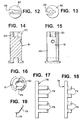
- FIGURES 17-19 the preferred construction of spring plate 78 is depicted.
- dials 34 can be arcuately rotated into any desired position. By individually rotating each dial 34 into a particular desired position, a unique or personalized code or sequence is created. Once each dial has been placed into the precisely desired position or alignment, shackle 22 is axially moved upwardly, bringing the locking fins 35 of each tumbler 33 into engagement in one slot 40 of one dial 34. Once these steps have been completed, the precisely desired new combination or code is established.
- dual mode padlock 20 of the present invention also incorporates key controlled locking section 24 formed as a part of housing 21 for enabling padlock 20 to be unlocked in a separate and independent alternate manner.
- key controlled locking section 24 formed as a part of housing 21 for enabling padlock 20 to be unlocked in a separate and independent alternate manner.
- key controlled locking section 24 of housing 21 incorporates elongated bore 80 extending from top surface 50 through to bottom surface 51. As depicted, elongated bore 80 extends substantially parallel to elongated bore 56 formed in combination controlled locking section 23.
- key controlled locking section 24 incorporates cooperating cylinders 81 and 82.
- Cylinders 81 and 82 are each rotationally journalled in elongated bore 80 and are mounted in controlled engagement with each other. If desired, a single elongated cylinder may be employed. However, it has been found for ease of construction, the use of two separate cylinders is preferred. In order to assure that cylinders 81 and 82 are arcuately pivoted simultaneously, effectively functioning as a single elongated cylinder, cylinder 81 incorporates channel 83 formed in the bottom surface thereof, while cylinder 82 incorporates an upstanding flange or ridge 84 formed in its top section. By lockingly engaging flange/ridge 84 in channel 83, cylinders 81 and 82 are arcuately pivoted simultaneously.
- key controlled locking section 24 incorporates locking collar 29 which is constructed for controlled engagement with terminating end 26 of short leg 25 of shackle 22.
- locking collar 29 is formed with a substantially U-shape as an integral component of cylinder 81, thereby assuring that the arcuate pivoting movement of locking collar 29 occurs simultaneously with the arcuate pivoting movement of cylinders 81 and 82.
- cylinder 82 incorporates key receiving slot 88 formed in the base thereof which is constructed for cooperating controlled relationship with key 89. Furthermore, cylinder 82 incorporates a plurality of spring biased tumblers 87 which are constructed for cooperating with cut-out zones formed on key 89.
- tumblers 87 prevent the arcuate movement of cylinder 82 unless all tumblers 87 are positioned in a precise, predetermined alignment and/or arrangement. When in the desired aligned position, cylinder 82 is capable of being arcuately rotated.
- key 89 is employed for axially positioning each tumbler 87 in the precisely desired, predetermined position.
- key 89 provides the necessary leverage for enabling cylinder 82 to be arcuately pivoted.
- tumblers 87 are aligned in the precisely desired predetermined position, enabling cylinder 82 to be arcuately rotated.
- flange 84 of cylinder 82 is engaged within channel or slot 83 of tumbler 82, the arcuate pivoting movement of the cylinder 82 simultaneously causes cylinder 81 to arcuately pivot therewith.
- locking collar 29 formed as an integral component of cylinder 81, the arcuate pivoting movement of cylinder 81 causes locking collar 29 to also pivot.
- U-shaped locking collar 29 incorporates slot or portal 30, which is normally positioned inwardly, generally facing housing 21 and preventing shackle 22 from being arcuately pivoted about its longitudinal axis.
- slot/portal 30 faces outwardly towards the side surface of housing 21, enabling terminating end 26 of leg 25 of shackle 22 to be arcuately pivoted out of engagement with locking collar 29, thereby releasing shackle 22 from locked engagement therein. In this way, the second separate and independent locking mode for padlock 20 is easily activated, in complete control by the user.
- a holding pin 82 is mounted in housing 21 and engaged within slotted opening 86 formed in cylinder 82. In this way, cylinder 82 is freely pivotal about its central axis, while being incapable of axial movement in bore 80 of housing 21.
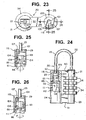
- FIGURES 20-26 a second preferred embodiment of dual mode padlock 20 of the present invention is depicted.
- a minimum of principal components is also employed, thereby achieving a dual mode padlock, while also substantially reducing the complexity found in most prior art padlocks.
- the present invention provides a highly effective, commercially desirable construction which is capable of being produced at a competitive cost, while also providing the unique attributes of the present invention and all of the locking and theft deterrent features typically incorporated in prior art padlocks.
- the two principal components which form the dual mode padlock 20 comprise central housing 21 and shackle 22, with central housing 21 incorporating combination controlled locking section 23 formed on one side thereof and key controlled locking section 24 formed on the opposed side thereof.
- the components required for forming and operating combination controlled locking section 23, as well as the components required for forming and operating key controlled locking section 24 are all detailed below.
- the cooperative engagement of shackle 22 with housing 21 is employed.
- shackle 22 comprises a conventional J-shape incorporating short leg 25 which has a terminating end 26, and long leg 27 having terminating end portion or section 28.
- shackle 22 is in its locked and fully engaged position when a major portion of long leg 27 is contained within housing 21 and terminating end 26 of short leg 25 is engaged within locking collar 29.
- terminating end 26 of short leg 25 must be released or disengaged from locking collar 29.
- short leg 25 is engaged or released from locking collar 29 by activating one of the two locking sections formed in housing 21.
- combination controlled locking section 23 By employing combination controlled locking section 23, and properly inputting the correct preset combination, the long leg 27 of shackle 22 is released and is able to move longitudinally or axially relative to housing 21. This longitudinal or axial movement enables terminating end 26 of short leg 25 to be axially removed from locking collar 29 resulting in the opening of dual mode padlock 20, as shown in FIGURE 5 .
- wall member 100 of locking collar 29 is moved vertically, relative to housing 21, effectively forming portal or open zone 101 in collar 29 which allows shackle 22 to be arcuately pivotable relative to housing 21, enabling terminating end 26 of short leg 25 to be moved out of engagement within locking collar 29, as shown in FIGURE 26 .
- shackle 22 is released from locked engagement with collar 29, enabling the removal of padlock 20 from the items to which it had been secured or, alternatively, enabling items to be securely engaged therewith.
- combination controlled locking section 23 of this embodiment of the present invention is constructed in a manner substantially identical to the embodiment detailed above.
- combination controlled locking section 23 incorporates four separate and independent tumbler sleeves 33 and four separate and independent rotatable dials 34.
- each tumbler sleeve 33 comprises a generally cylindrical shape incorporating a single locking fin 35 radially extending from outer, circular-shaped surface 36.
- each tumbler sleeve 33 also comprises an inside, circular-shaped surface 37 which is coaxially aligned with outside surface 36. The diameter of inside surface 37 of tumbler sleeve 33 is constructed to enable each tumbler sleeve 33 to freely pivot about the outer surface of shackle 22.
- Each dial 34 is constructed for peripherally surrounding and cooperating with a tumbler sleeve 33.
- each dial 34 comprises two separate and distinct, circular-shaped inside surfaces 38 and 39.
- Side surface 38 comprises a diameter slightly greater than the diameter of outside surface 36 of tumbler sleeve 33, in order to enable tumbler sleeve 33 and dial 34 to cooperate with each other while being independently rotationally movable about 22.
- each dial 34 comprises a plurality of slots 40 formed in inside surface 38, with each slot being constructed for receiving and retaining radially extending fin 35 of tumbler sleeve 33. In this way, whenever radially extending fin 35 is mounted in a slot 40 of dial 34, tumbler sleeve 33 and dial 34 are in interlocked engagement, causing both members to rotate together about shackle 22.
- the number of slots 40 formed in dial 34 corresponds to the number of separate and distinct indicia formed on the outer surface of dial 34.
- ten indicia are employed on the outside surface of dial 34 and ten slots 40 are formed in surface 38.
- dial 34 Inside surface 39 of dial 34 comprises a circular shape formed by a diameter which is aligned with the axis of surface 38, but is greater than the length of fin 35. In this way, when fin 35 is disengaged from slot 40 of dial 34, dial 34 is able to rotate about shackle 22 independently of tumbler sleeve 33. Each tumbler sleeve 33 is rotationally mounted to leg 27 of shackle 22, with each tumbler sleeve having a dial 34 rotationally associated therewith.
- each dial 34 has a plurality of indicia formed on the outer peripheral surface thereof, each of which represents one component of the combination for positioning tumbler sleeves 33 in the requisite location for releasing shackle 22.
- indicia any desired indicia can be employed, numerals or letters are typically employed on prior art constructions.
- each dial 34 comprises an outer surface 44 on which ten panels 45 are formed with slots separating each panel 45.
- one numeral ranging from 0, 1, 2, 3, 4, 5, 6, 7, 8 and 9 is formed on each panel 45. The numeral in each panel 45 of each dial 24 is then employed to define the combination for padlock 20.
- leg 27 of shackle 22 incorporates ribs 48 and 49 formed on the outer surface thereof and a locking ring receiving slot 50 formed directly adjacent terminating end section 28 of leg 27 of shackle 22.
- the axial distance between ribs 48 and 49 and slot 50 is constructed for being substantially equivalent to the axial length required for enabling locking ring 46, when mounted in slot 50, to retain the four tumbler sleeves 33 on leg 27 of shackle 22, with each tumbler sleeves 33 being capable of independent rotational movement, while substantially eliminating any axial movement thereof.
- tumbler sleeves 33 are able to provide the desired locking and unlocking function, while achieving this result in an easily manufactured and easily assembled construction.
- a visual indicator of the proper orientation for each numeral or letter of each panel 45 of each dial 34 is also provided by incorporating on housing 21 a position orientating line. This line enables the user to visually position each numeral in the proper location for a pre-set combination.
- housing 21 comprises a single piece construction, within which various cavities, bores, and receiving zones are formed for enabling the dual, independent, locking systems to operate.
- housing 21 comprises a top surface 50, a bottom surface 51, a front panel 52, a rear panel 53, and two side panels 54 and 55.
- cover panels 98 and 99 are mounted to housing 21 for peripherally surrounding and enveloping housing 21. In this way, any desired outer surface configuration, color, visual appearance etc. can be attained for providing a desired aesthetic appeal and/or providing added protection to the surface of the housing.
- combination controlled locking section 23 of housing 21 incorporates a central, elongated bore 56 which extends through section 23 from top surface 50 to bottom surface 51.
- bore 56 comprises portal 68, formed with top surface 50.
- bore 56 comprises three separate diameters, forming three separate and independent coaxial zones 57, 58, and 59.
- Zone 57 comprises the lowermost zone of bore 56, and comprises a diameter slightly greater than the diameter of shackle 22. In this way, terminating end section 28 of leg 27 of shackle 22 is capable of axial movement in zone 57, while also preventing any other components mounted to leg 33 of shackle 22 from entering zone 57.
- Zone 58 comprises the intermediate zone of bore 56 and has a diameter slightly greater than the outside diameter of tumbler sleeves 33. In this way, tumbler sleeves 33 are capable of axial movement through zone 58 of central bore 56.
- zone 58 also comprises an elongated slot or channel 60 formed along one wall of zone 58, providing the release position for each radially extending fin 35 of each tumbler sleeve 33.
- shackle 22 when each locking fin of each tumbler sleeve 33 is aligned with release channel 60, shackle 22 is capable of axial movement, thereby enabling shackle 22 to be removed from its locked position or, if desired, inserted into its locked position, or axially advanced into zone 57 of bore 56 of housing 21, to enable the combination to be changed, set or re-set.
- the final zone of bore 56 is upper zone 59 which comprises the largest diameter of bore 56.
- the diameter of zone 59 is constructed to enable each tumbler sleeve 33 with its radially extending fin 35 to be easily advanced through first portal 68 of zone 59. In this way, assembly of combination section 23 of padlock 20 is easily attained.
- sealing cap 47 comprises a cylindrical shape formed by outer surface 70 and upper flange 71.
- the diameter of zone 59 is substantially equivalent to the diameter of outer surface 70 of cap 47 in order to require cap 37 to be forced into first portal 68 and zone 59 and, once inserted therein, securely affixed thereto.
- tumbler sleeves 34 and locking ring 46 are mounted to leg 27 of shackle 22. Then, when dials 34 are mounted in place, the fully assembled leg 27 of shackle 22 is inserted into first portal 68 of bore 56 of housing 21. The assembly is then completed by forcing sealing cap 47 into first portal 68 of zone 59 of bore 56 until the entire outer surface 70 of cap 47 is fully engaged in zone 59 and peripheral flange 71 contacts top surface 50.
- combination controlled locking section 23 of housing 21 incorporates four separate and independent dial receiving zones 61.
- Each dial receiving zone 61 is formed in juxtaposed spaced aligned parallel relationship with each other, while also being cooperatively associated with zone 58 of central bore 56 and elongated release channel 60.
- each dial receiving zone 61 is defined by an upper surface 62 and a lower surface 63 which are parallel to each other. If desired, each dial receiving zone 61 may be cooperatively associated with a spring plate as detailed above. However, if desired, this component may be eliminated.
- dials 34 can be arcuately rotated into any desired position. By individually rotating each dial 34 into a particular desired position, a unique or personalized code or sequence is created. Once each dial has been placed into the precisely desired position or alignment, shackle 22 is axially moved upwardly, brining the locking fins 35 of each tumbler 33 into engagement in one slot 40 of one dial 34. Once these steps have been completed, the precisely desired new combination or code is established.
- this embodiment of dual mode padlock 20 of the present invention also incorporates key controlled locking section 24 formed as a part of housing 21 for enabling padlock 20 to be unlocked in a separate and independent alternate manner.
- key controlled locking section 24 formed as a part of housing 21 for enabling padlock 20 to be unlocked in a separate and independent alternate manner.
- key controlled locking section 24 of housing 21 incorporates elongated bore 110 extending from top surface 50 through to bottom surface 51. As depicted, elongated bore 110 extends substantially parallel to elongated bore 56 formed in combination controlled locking section 23.
- key controlled locking section 24 incorporates cooperating cylinders 111 and 112.
- Cylinders 111 and 112 are each rotationally journalled in elongated bore 110 and are mounted in controlled engagement with each other. If desired, a single elongated cylinder may be employed. However, it has been found for ease of construction, the use of two separate cylinders is preferred. In order to assure that cylinders 111 and 112 are arcuately pivoted simultaneously, effectively functioning as a single elongated cylinder, cylinder 111 incorporates channel 113 formed in the bottom surface thereof, while cylinder 112 incorporates an upstanding flange or ridge 114 formed in its top section. By lockingly engaging flange/ ridge 114 in channel 113, cylinders 111 and 112 are arcuately pivoted simultaneously.
- cylinder 112 preferably incorporates axial slotted aperture 86 formed therein which cooperates with pin 85 mounted through housing 21 for extending into aperture 86. In this way, axial movement of cylinders 111 and 112 is prevented, while assuring free pivotal movement therein.
- locking collar 29 which is constructed for controlled engagement with terminating end 26 of short leg 25 of shackle 22.
- locking collar 29 comprises a substantially circular shaped member incorporating support base 102 on which upstanding, generally U-shaped wall portion 103 is formed.
- portal or open zone 101 is formed between the terminating ends of wall portion 103.
- locking collar 29 is securely mounted in elongated bore 110 directly adjacent top surface 50 of housing 21.
- locking collar 29 is press-fitted or frictionally engaged in bore 110 in order to assure movement-free affixation of locking collar 29 with housing 21.
- portal/open zone 101 of locking collar 29 is positioned in alignment with cutout zone 115 formed in housing 21 for cooperating with locking collar 29. In this way, a pathway is established for the passage of short leg 25 of shackle 22 when key controlled section 24 of padlock 20 is in the open position, as is detailed below.
- this embodiment of padlock 20 incorporates movable plate member 100, which is constructed for co-operating with locking collar 29, portal/open zone 101, and cutout zone 115.
- plate member 100 is constructed for being vertically movable relative to locking collar 29, for effectively opening and closing portal/open zone 101 and cutout zone 115. In this way, the arcuate pivoting movement of shackle 22 about the axis of its long leg 27 is completely controlled by locking section 24 of padlock 20.
- cylinders 111 and 112 are coaxially mounted in elongated bore 110 for rotational movement therein about the central axes of cylinders 111 and 112.
- rotational movement of cylinders 111 and 112 is attainable only when the designated key 89 is inserted in the key receiving slot formed in cylinder 112.
- the key-controlled rotational movement of cylinder 112 causes cylinder 111 to rotate simultaneously therewith, due to the secure interengagement of cylinders 111 and 112.
- cylinder 111 is constructed with a substantially circular shaped base portion 118, with channel 113 formed in one end thereof. On the opposed end, axially extending support pin 119 is formed, with circular shaped plate 120 mounted on the opposed end of pin 119. Finally, the construction of cylinder 111 is completed by positioning upstanding, axially extending, substantially cylindrical post 121 on the upper surface of plate 120, with post 121 comprising a substantially flat, top surface 122 and a curved outer surface 123. In addition, as depicted, post 121 is constructed with an overall diameter less than the diameter of plate 120 and base 118.
- Post 121 also incorporates cam slot 124 formed in curved, outer surface 123, with cam slot 124 extending at a sloping angle relative to substantially flat top surface 122.
- the slope angle employed for cam slot 124 ranges between about 30° and 60°.
- sloping cam slot 124 terminates directly adjacent top surface 122, in a substantially horizontally extending section 125, with section 125 extending substantially parallel to top surface 122.
- movable plate member 100 is mounted in elongated bore 110 directly adjacent top surface 50 of housing 21 in co-operating relationship with locking collar 29, while also being movably controlled by the rotation of cylinder 111.
- movable plate member 100 comprises wall member 104, having an inside surface 105 and outside surface 106, with wall member 104 being constructed with an arcuately curved configuration that is dimensioned for insertion in co-operating sliding engagement with elongated bore 110.
- the overall thickness of wall member 104 is constructed for nested, sliding engagement between outer surface 123 of post 121 and the inside surface of bore 110.
- plate member 100 incorporates arcuately curved blocking segment 107 which is mounted to inside surface 106 of wall member 104. As depicted, blocking segment 107 is mounted near the upper edge of wall member 104, with a portion of blocking segment 104 extending beyond the terminating upper edge of wall member 104. Finally, the construction of movable plate member 100 is completed by forming cam follower pin 108 on inside surface 105 of wall member 104, positioned near the bottom edge thereof, with pin 108 radially extending inwardly from wall member 104.
- blocking segment 107 is dimensioned with an overall, arcuately curved width which is substantially equivalent to the arcuate curved width of portal/open zone 101 of locking collar 29. In this way, as shown in FIGURE 25 , when movable plate member 100 is in its first, upper, raised position, blocking segment 107 effectively closes upstanding, U-shaped wall portion 103, sealing portal/open zone 101 and effectively locking short leg 25 of shackles 22 in locking collar 29 by peripheral, surrounding engagement thereof.
- plate member 100 is positioned in elongated bore 111 with the movement thereof completely controlled by the rotational movement of cylinder 111.
- outside surface 106 of wall member 104 is positioned in sliding engagement with the inside surface of bore 110, while inside surface 105 of wall member 104 is positioned in sliding engagement with outside surface 123 of post 121.
- radially extending, follower pin 108 is mounted in cam slot 124 and/or slot 125 for controlled movement therein.
- cylinders 111 and 112 causes plate member 100 to vertically move between its first positioned and its second position.
- cylinders 111 and 112 are capable of only rotational movement about their central axes. Vertical movement of cylinders 111 and 112 is prevented. Consequently, when the designated key is inserted into cylinder 112 for enabling cylinder 112 to be rotated about its central axis, cylinder 111 simultaneously rotates therewith. This rotational movement causes follower pin 108 to first move from extension slot 125 into sloping cam slot 124 and, thereafter, to move through sloping slot 124.
- cylinder 112 incorporates key receiving slot 88 formed in the base thereof which is constructed for cooperating controlled relationship with key 89. Furthermore, cylinder 112 incorporates a plurality of spring biased tumblers 87 which are constructed for cooperating with cut-out zones formed on key 89.
- tumblers 87 prevent the arcuate movement of cylinder 112 unless all tumblers 87 are positioned in a precise, predetermined alignment and/or arrangement. When in the desired aligned position, cylinder 112 is capable of being arcuately rotated.
- key 89 is employed for axially positioning each tumbler 87 in the precisely desired, predetermined position.
- key 89 provides the necessary leverage for enabling cylinder 112 to be arcuately pivoted.
Landscapes
- Lock And Its Accessories (AREA)
- Switch Cases, Indication, And Locking (AREA)
Claims (20)
- Vorhängeschloss, das so aufgebaut ist, dass zwei getrennte und unabhängige Schließmittel in einer einzelnen, integrierten Ausführung bereitgestellt werden, wobei eine erste Schließeinheit durch eine Kombination und eine zweite Schließeinheit durch Schlüssel betätigt werden, wobei das Vorhängeschloss Folgendes umfasst:ein Gehäuse (21), das Folgendes beinhaltet:eine erste längliche Bohrung (56) und eine zweite längliche Bohrung (80, 110),mehrere Drehscheibenaufnahmezonen (61), die im Gehäuse (21) in einer der ersten länglichen Bohrung (56) zugeordneten Ausführung ausgebildet sind, undeinen länglichen Freigabekanal (60), der in der ersten länglichen Bohrung (56) ausgebildet ist und sich axial damit erstreckt, wobei der längliche Freigabekanal (60) eine Zone definiert, in der die durch Kombination betätigte Schließeinheit entsperrt werden kann;Schließmittel in der Form eines Bügels (22), der eine allgemein J-förmige Form aufweist und Folgendes beinhaltet:einen kurzen Schenkel (25) mit einem Abschlussende, das so ausgeführt ist, dass ein zusammenwirkender Schließ- und Entsperrungseingriff mit einem im Gehäuse (21) montierten Haltekragen (29) möglich ist, undeinen langen Schenkel (27), der in zusammenwirkender Weise in der ersten länglichen Bohrung (56) des Gehäuses (21) so montiert ist, dass eine axiale Bewegung und eine Schwenkbewegung im Verhältnis dazu durchführbar sind;mehrere Zuhaltehülsen (33), wobei jede der Zuhaltehülsen drehbar am langen Schenkel (27) des Bügels (22) montiert ist, um eine Drehbewegung um dessen zentrale Achse zu ermöglichen, und wobei jede der Zuhaltehülsen eine sich radial erstreckende Rippe (35) beinhaltet, die an der Außenfläche davon ausgebildet und so ausgeführt ist, dass eine zusammenwirkende Zuordnung zum länglichen Freigabekanal (60) geschaffen wird, um eine axiale Bewegung des langen Schenkels (27) des Bügels zu verhindern sowie eine axiale Bewegung davon zu ermöglichen, wenn jede der radialen Rippen im länglichen Freigabekanal positioniert ist;mehrere Drehscheiben (34), wobei jede der Drehscheiben1. in einer Drehscheibenaufnahmezone (61) des Gehäuses (21) montiert ist, und2. am Umfang eine Zuhaltehülse (33) umgibt, um damit zusammenzuwirken, wobei die durch Kombination betätigte Einheit des Vorhängeschlosses geschaffen wird; undeine durch Schlüssel betätigte Schließeinheit, die in der zweiten länglichen Bohrung (80, 110) des Gehäuses (21) montiert und so aufgebaut ist, dass sie auf ein zugewiesenes Schlüsselelement (89) reagiert, um eine Bewegung zwischen einer ersten Position, in der sich der Bügel (22) in verriegeltem Eingriff befindet, und einer zweiten Position, in der der Bügel (22) entsperrt und bewegbar ist, zu ermöglichen, wobei die Schließeinheit Folgendes umfasst:eine Zylindereinheit, diein der zweiten länglichen Bohrung (80) montiert ist, um darin eine kontrollierte Drehbewegung zu ermöglichen, undeinen Schlüsselaufnahmeschlitz (88) beinhaltet, der in zusammenwirkender Weise mehreren Zuhaltungen (87) zugeordnet ist, um die Drehbewegung des Zylinders immer dann zu verhindern, wenn das zugewiesene Schlüsselelement (89) nicht vorhanden ist, und der eine Drehbewegung des Zylinders in Reaktion auf das Vorhandensein des zugewiesenen Schlüsselelements (89) ermöglicht, undden Haltekragen (29), dereinen Bügeleingriffskragen (29) bildet, der in zusammenwirkender Weise dem Abschlussende des kurzen Schenkels (25) des Bügels (22) zugeordnet ist und auf die Drehbewegung des Zylinders reagiert, um eine Bewegung des Bügels (22) in einer ersten Position zu verhindern sowie eine Bewegung des Bügels (22) zu ermöglichen, wenn sich die Zylindereinheit in einer zweiten Position befindet.
- Vorhängeschloss nach Anspruch 1, bei dem der Bügeleingriffskragen (29) allgemein U-förmig, aufrecht ausgebildet und in der zweiten länglichen Bohrung (80, 110) des Gehäuses (21) montiert und so ausgebildet ist, dass er den Umfang des Abschlussendes des kurzen Schenkels (25) des Bügels (22) im Wesentlichen vollständig umgibt, wobei ein Abschnitt des Kragens (29) eine offene Zone (101) bildet, um die bogenförmige Schwenkbewegung des Bügels (22) um die zentrale Achse des langen Schenkels davon zu kontrollieren.
- Vorhängeschloss nach Anspruch 1, bei dem die Zylindereinheit, die einen Teil der durch Schlüssel betätigten Schließeinheit davon bildet, weiterhin ein erstes, im Wesentlichen zylindrisch geformtes Element (82, 112) und ein zweites, im Wesentlichen zylindrisch geformtes Element (81, 111) umfasst, die beide koaxial in ineinandergreifender und miteinander zusammenwirkender Weise montiert sind.
- Vorhängeschloss nach Anspruch 3, bei dem das erste, im Wesentlichen zylindrisch geformte Element (82) weiterhin den Schlüsselaufnahmeschlitz (88), der in einem ersten Ende davon ausgebildet ist, sowie eine aufrechte Leiste (84) beinhaltet, die an einem zweiten Ende davon ausgebildet ist.
- Vorhängeschloss nach Anspruch 4, bei dem das zweite, im Wesentlichen zylindrisch geformte Element (81) weiterhin einen Schlitz umfasst, der in einem ersten Ende davon ausgebildet ist, wobei der Schlitz so positioniert ist, dass er in zusammenwirkender Weise in die aufrechte Leiste (83) des ersten zylindrisch geformten Elements (82) eingreift, wobei die Drehbewegung des ersten zylindrisch geformten Elements (82) eine Drehbewegung des zweiten zylindrisch geformten Elements (81) bewirkt.
- Vorhängeschloss nach Anspruch 5, bei dem der U-förmige Bügeleingriffskragen (29) weiterhin an einem zweiten Ende des zweiten zylindrisch geformten Elements (81) integral ausgebildet ist, um mit der Bewegung des zweiten zylindrisch geformten Elements (81) eine bogenförmige Schwenkbewegung um dessen zentrale Achse durchzuführen, wobei in wirksamer Weise ein bewegbares Portal oder eine offene Zone (101) für den kurzen Schenkel (25) des Bügels (22) um seine zentrale Achse gebildet wird, wobei die bogenförmige Schwenkbewegung des Bügels (22) blockiert ist, wenn sich die offene Zone (101) des Kragens (29) in einer ersten Blockierposition befindet, und eine bogenförmige Schwenkbewegung des Bügels (22) ermöglicht wird, wenn sich die offene Zone (101) des Kragens (29) in einer zweiten Position in Ausrichtung mit dem Bewegungspfad des Bügelschenkels befindet.
- Vorhängeschloss nach Anspruch 6, bei dem der U-förmige Bügeleingriffskragen (29) eine Schwenkbewegung durch einen Bogen von etwa 90° in Reaktion auf die bogenförmige Schwenkbewegung der Zylindereinheit durch einen Bogen von etwa 90° durchführt, wobei in wirksamer Weise die offene Zone (101) des U-förmigen Kragens (29) zwischen ihren zwei wechselnden Positionen bewegt wird, und wobei in wirksamer Weise eine Bewegung des Bügels (22) verhindert wird, wenn sich die offene Zone (101) des Kragens (29) in ihrer ersten Position befindet, und eine Bewegung des Bügels (22) ermöglicht wird, wenn sich die offene Zone des Kragens (29) in ihrer zweiten Position befindet.
- Vorhängeschloss nach Anspruch 2, das weiterhin ein Plattenelement (100) umfasst, das in zusammenwirkender Weise der offenen Zone (101) des U-förmigen Bügeleingriffskragens (29) zugeordnet ist, um die offene Zone (101) zu blockieren, wenn sich das Plattenelement (100) in einer ersten Position befindet, und die offene Zone (101) zu schaffen, wenn sich das Plattenelement in einer zweiten Position befindet, wobei die Bewegung des Plattenelements (100) in wirksamer Weise eine Schwenkbewegung des Bügels (22) in seiner ersten Position blockiert und eine Schwenkbewegung des Bügels (22) in seiner zweiten Position ermöglicht.
- Vorhängeschloss nach Anspruch 8, bei dem das Plattenelement (100) weiterhin im Verhältnis zum U-förmigen Bügeleingriffskragen (29) in zusammenwirkender Ausrichtung zur offenen Zone (101) davon vertikal bewegbar ist, um in wirksamer Weise die Bewegung des Bügels (22) in einer ersten Position zu blockieren und eine Bewegung des Bügels (22) in einer zweiten Position zu ermöglichen.
- Vorhängeschloss nach Anspruch 9, bei dem das Plattenelement (100) in kontrollierbarer Weise in das zweite, im Wesentlichen zylindrisch geformte Element (111) eingreift, um in Reaktion auf die Drehbewegung des zweiten zylindrisch geformten Elements (111) vertikal bewegbar zu sein.
- Vorhängeschloss nach Anspruch 10, bei dem das zweite, im Wesentlichen zylindrisch geformte Element (111) einen darin ausgebildeten Nockenschlitz (124) beinhaltet, und wobei das Plattenelement (100) einen sich radial erstreckenden, im Nockenschlitz (124) montierten Abtaststift (108) beinhaltet, um in wirksamer Weise zu bewirken, dass sich das Plattenelement (100) in Reaktion auf die Drehbewegung des zweiten zylindrischen Elements (111) vertikal bewegt, wobei das Plattenelement (100) in kontrollierbarer Weise zwischen seiner ersten Blockierposition und seiner zweiten entsperrten Position bewegt wird.
- Vorhängeschloss nach Anspruch 11, bei dem der Nockenschlitz (124) weiterhin einen ersten Bereich, der im Verhältnis zur zentralen Achse des zweiten zylindrisch geformten Elements (111) einen schrägen Winkel aufweist, sowie einen zweiten Bereich (125) umfasst, der am oberen Ende des ersten Bereichs ausgebildet ist und sich im Wesentlichen senkrecht zur zentralen Achse des zweiten zylindrisch geformten Elements (111) erstreckt.
- Vorhängeschloss nach Anspruch 12, bei dem der schräge Winkel des ersten Bereichs des Nockenschlitzes (124) in einem Bereich von etwa 30° bis 60° liegt.
- Vorhängeschloss nach Anspruch 11, bei dem das Plattenelement (100) weiterhin einen bogenförmig gekrümmten Wandabschnitt umfasst, der in der zweiten länglichen Bohrung (110) zwischen der Innenwand der zweiten länglichen Bohrung (110) und der Außenfläche des zweiten zylindrisch geformten Elements (111) montiert ist, um dazwischen eine vertikale Bewegung zuzulassen.
- Vorhängeschloss nach Anspruch 14, bei dem das Plattenelement (100) weiterhin einen Blockierabschnitt (107) umfasst, der an der Innenfläche (106) des Wandabschnitts (104) montiert und so positioniert ist, dass eine zusammenwirkende Bewegung im Verhältnis zur im U-förmigen Bügeleingriffskragen (29) ausgebildeten offenen Zone möglich ist.
- Vorhängeschloss nach Anspruch 1, bei dem die erste längliche Bohrung (56) drei separate und getrennte Zonen umfasst, die durch eine unterste Zone (57), eine zentrale Zone (58) und eine oberste Zone (59) gebildet sind, wobei jede Zone unterschiedliche Durchmesser aufweist, und wobei die unterste Zone (57) den kleinsten Durchmesser und die oberste Zone (59) den größten Durchmesser umfasst.
- Vorhängeschloss nach Anspruch 16, bei dem jede der Drehscheiben (34) weiterhin eine allgemein zylindrische Form mit mehreren kennungstragenden Feldern auf einer Außenfläche davon umfasst, um leicht identifizierbare Kennungen zu schaffen, die Elemente definieren, die als Kombination verwendbar sind, um den Freigabemodus des ersten Schließmittels zu definieren.
- Vorhängeschloss nach Anspruch 17, bei dem jede der Drehscheiben (34) weiterhin einen Schlitz umfasst, der an der Außenfläche davon zwischen jedem angrenzenden kennungstragenden Feld ausgebildet ist.
- Vorhängeschloss nach Anspruch 18, bei dem das Gehäuse weiterhin einen Hohlraum direkt angrenzend an jede Drehscheibenaufnahmezone umfasst, wobei das erste Schließmittel weiterhin ein Feder- und Stiftelement umfasst, das in jedem Hohlraum montiert ist, um einen zusammenwirkenden Eingriff mit jeder Drehscheibe (34) zu ermöglichen, wobei eine Anzeige für die Bezeichnung der Position der sich drehbaren Drehscheibe geschaffen und angezeigt wird, wenn sich jedes Feld in einer gewünschten Orientierung befindet, um so ein Element der Kombination zu bezeichnen.
- Vorhängeschloss nach Anspruch 19, bei dem jede der Zuhaltehülsen (33) weiterhin am langen Schenkel (27) des Bügels (22) montiert ist, um eine Drehbewegung um die Achse des Bügels (22) zu ermöglichen, während eine translatorische Bewegung entlang der Achse des langen Schenkels des Bügels (22) im Wesentlichen nicht möglich ist.
Applications Claiming Priority (4)
| Application Number | Priority Date | Filing Date | Title |
|---|---|---|---|
| US517006 | 1983-07-25 | ||
| US51700603P | 2003-11-04 | 2003-11-04 | |
| US850838 | 2004-05-21 | ||
| US10/850,838 US7140209B2 (en) | 2003-11-04 | 2004-05-21 | Padlock with fully integrated dual locking systems |
Publications (3)
| Publication Number | Publication Date |
|---|---|
| EP1529907A2 EP1529907A2 (de) | 2005-05-11 |
| EP1529907A3 EP1529907A3 (de) | 2010-03-03 |
| EP1529907B1 true EP1529907B1 (de) | 2012-12-12 |
Family
ID=34437348
Family Applications (1)
| Application Number | Title | Priority Date | Filing Date |
|---|---|---|---|
| EP20040256580 Expired - Lifetime EP1529907B1 (de) | 2003-11-04 | 2004-10-26 | Vorhängeschloss mit zwei getrennten unabhängigen Schliesssystemen |
Country Status (3)
| Country | Link |
|---|---|
| US (1) | US7140209B2 (de) |
| EP (1) | EP1529907B1 (de) |
| JP (1) | JP2005139895A (de) |
Cited By (6)
| Publication number | Priority date | Publication date | Assignee | Title |
|---|---|---|---|---|
| WO2020125617A1 (en) * | 2018-12-18 | 2020-06-25 | The Sun Lock Company Limited | Combination padlock with anti-picking and decode mechanism |
| US11713593B2 (en) | 2019-12-18 | 2023-08-01 | The Sun Lock Company Limited | Hook lock with dual locking function with key captive design |
| USD1011865S1 (en) | 2022-01-05 | 2024-01-23 | The Sun Lock Company Limited | Combination padlock |
| US12037816B2 (en) | 2020-08-28 | 2024-07-16 | The Sun Lock Company Limited | Dual locking combination padlock with decode function |
| US12281500B2 (en) | 2021-08-06 | 2025-04-22 | The Sun Lock Company Limited | High security combination padlock and locking bar with advanced anti-picking mechanism |
| USD1102867S1 (en) | 2023-09-06 | 2025-11-25 | The Sun Lock Company Limited | Combination padlock |
Families Citing this family (58)
| Publication number | Priority date | Publication date | Assignee | Title |
|---|---|---|---|---|
| TWM247655U (en) | 2003-01-29 | 2004-10-21 | Jiun-De You | Lock specific for security inspection |
| TW590146U (en) | 2003-05-14 | 2004-06-01 | Sinox Co Ltd | Padlock structure with hook locking and opening |
| US7159422B1 (en) * | 2003-08-05 | 2007-01-09 | The Eastern Company | Combination and key operated padlock with indicator |
| US7832238B2 (en) | 2003-08-05 | 2010-11-16 | The Eastern Company | Combination and key operated locks with indicators |
| US7363782B1 (en) | 2003-08-05 | 2008-04-29 | The Eastern Company | Combination and key operated padlock with indicator |
| US8881558B2 (en) | 2003-08-05 | 2014-11-11 | The Eastern Company | Combination and key operated locks with indicators |
| USD674266S1 (en) | 2003-08-05 | 2013-01-15 | The Eastern Company | Cable shackle padlock having a sidewall aperture for a status indicator |
| US20050034492A1 (en) * | 2003-08-15 | 2005-02-17 | Yu Chun Te | Padlock |
| US20060225469A1 (en) * | 2003-09-29 | 2006-10-12 | Yu Chun T | Padlock with block member |
| US7210318B2 (en) * | 2003-09-29 | 2007-05-01 | Chun Te Yu | Padlock |
| US20050126233A1 (en) * | 2003-09-30 | 2005-06-16 | Chun-Te Yu | Hanging lock structure |
| US7225648B2 (en) * | 2003-11-04 | 2007-06-05 | The Sun Lock Company Ltd. | Padlock with fully integrated dual locking system with indicator/signal assembly |
| US8145576B2 (en) * | 2003-11-12 | 2012-03-27 | Iowa Hawkeyes LLC | Method of facilitating screening of airline luggage |
| TWM256895U (en) * | 2004-01-20 | 2005-02-11 | Fullyear Brother Entpr Co Ltd | Improved structure of padlock |
| US7370497B2 (en) * | 2005-01-11 | 2008-05-13 | Chun Te Yu | Multifunctional padlock having shackle limit knob |
| TWI248999B (en) * | 2004-04-21 | 2006-02-11 | Sinox Co Ltd | Locking device with double-lock mechanism |
| US20080011027A1 (en) * | 2004-04-28 | 2008-01-17 | Yu Chun T | Padlock |
| TWI235778B (en) * | 2004-05-27 | 2005-07-11 | Sinox Co Ltd | State identification lock |
| AU2005203013A1 (en) * | 2004-07-08 | 2006-02-02 | Chun Te Yu | Padlock |
| TW200624646A (en) * | 2005-01-11 | 2006-07-16 | Jiun-De You | Padlock having an identification function |
| US7100401B2 (en) * | 2004-11-23 | 2006-09-05 | Chun Te Yu | Padlock having an identification function |
| TWM282017U (en) * | 2004-10-08 | 2005-12-01 | Jiun-De You | Double-locking lock device with reminder function |
| US7146830B2 (en) * | 2004-11-03 | 2006-12-12 | Chien-Yung Huang | Error-proofing combination padlock |
| US20120279264A1 (en) | 2005-01-11 | 2012-11-08 | Chun Te Yu | Padlock with indication device |
| US8256250B2 (en) * | 2004-11-23 | 2012-09-04 | Chun Te Yu | Padlock with indication device |
| US20080156046A1 (en) * | 2005-01-11 | 2008-07-03 | Chun Te Yu | Multifunctional padlock having shackle limit knob |
| US8353184B2 (en) | 2005-01-21 | 2013-01-15 | Sinox Company Ltd. | Tamper indicating padlock |
| TWM286264U (en) * | 2005-01-27 | 2006-01-21 | Jiun-De You | Double lock for locking an insertion |
| TWM281053U (en) * | 2005-03-30 | 2005-11-21 | Jiun-De You | Padlock structure capable of controlling open/close state of shackle |
| TWI276730B (en) * | 2005-05-11 | 2007-03-21 | Chun-Te Yu | Luggage lock with dual locking devices |
| TWI288792B (en) * | 2006-03-31 | 2007-10-21 | Sinox Co Ltd | Padlock having an open indication function |
| US20080178649A1 (en) * | 2006-08-15 | 2008-07-31 | Chun Te Yu | Lock with indicator and multiple key-operable core |
| US7293439B1 (en) * | 2007-02-02 | 2007-11-13 | Jin Tay Industries Co., Ltd. | Combination padlock |
| JP5022055B2 (ja) * | 2007-02-09 | 2012-09-12 | 有限会社ケイ・ワイ・ティ | 複合ロックアッセンブリ |
| US7685851B2 (en) * | 2007-04-13 | 2010-03-30 | The Sun Lock Company Ltd. | Security padlock having a secondary locking system |
| CN101280650B (zh) * | 2008-05-29 | 2011-05-18 | 尹复顺 | 多功能防盗锁 |
| KR200464724Y1 (ko) | 2011-01-26 | 2013-01-16 | 이상곤 | 번호교체용 다이얼 자물쇠 |
| US8931313B2 (en) * | 2011-07-25 | 2015-01-13 | The Sun Lock Company Ltd. | Lock with dual locking system |
| CN102304990A (zh) * | 2011-08-31 | 2012-01-04 | 东莞市怡丰锁业有限公司 | 一种机械密码锁 |
| US8776556B2 (en) * | 2011-11-15 | 2014-07-15 | The Sun Lock Company, Ltd. | Combination padlock with secondary opening mechanism |
| USD695976S1 (en) * | 2012-04-11 | 2013-12-17 | James C. Allen, JR. | Leash |
| US9194159B2 (en) * | 2013-06-11 | 2015-11-24 | ABUS August Bremicker Söhne KG | Padlock |
| CN106460407B (zh) | 2014-05-07 | 2018-09-04 | 特新实业有限公司 | 一种具有完全集成双锁定机构以及丢失密码定义系统的挂锁 |
| US9487969B2 (en) | 2014-10-10 | 2016-11-08 | The Sun Lock Company Ltd. | Combination padlock with anti-pick and anti-peek mechanism |
| US9803398B2 (en) | 2015-06-30 | 2017-10-31 | The Sun Lock Company Ltd. | Combination padlock with dual locking and advanced anti-pick mechanism |
| US9890559B2 (en) | 2015-03-25 | 2018-02-13 | The Sun Lock Company, Ltd. | Padlock with fully integrated dual locking mechanism with reset mechanism |
| US10221591B2 (en) | 2015-07-07 | 2019-03-05 | The Sun Lock Company, Ltd. | Padlock with fully integrated dual locking mechanism with reset mechanism |
| WO2017004719A1 (en) | 2015-07-09 | 2017-01-12 | Rynan Technologies Pte. Ltd. | Padlock |
| US10047541B2 (en) * | 2015-09-16 | 2018-08-14 | The Sun Lock Company, Ltd. | Dual locking system with user controllable plate |
| US10267062B2 (en) * | 2015-12-11 | 2019-04-23 | The Sun Lock Company, Ltd. | Electronic combination lock with different levels of access control |
| US10443272B2 (en) | 2017-05-04 | 2019-10-15 | The Sun Lock Company, Ltd. | Dual unlocking mode padlock |
| EP3682074B1 (de) | 2017-09-11 | 2022-06-08 | The Sun Lock Company Ltd. | Elektronisches kombinationsschloss mit verschiedenen stufen der zugangskontrolle |
| US11346127B2 (en) | 2019-06-27 | 2022-05-31 | The Sun Lock Company Limited | Hook lock with dual locking function |
| US11261622B2 (en) | 2019-08-28 | 2022-03-01 | The Sun Lock Company Limited | High security combination padlock with ease of use reset mechanism |
| USD902691S1 (en) | 2019-10-01 | 2020-11-24 | The Sun Lock Company Limited | Combination padlock |
| USD914481S1 (en) | 2019-10-15 | 2021-03-30 | The Sun Lock Company Limited | Padlock |
| US11866961B2 (en) * | 2021-10-08 | 2024-01-09 | Aba Locks International Co., Ltd. | Anti-vandal padlock |
| SE2250726A1 (en) * | 2022-06-16 | 2023-12-17 | Anchor Laas Ab | An improved padlock body for engaging with a locking cylinder |
Family Cites Families (16)
| Publication number | Priority date | Publication date | Assignee | Title |
|---|---|---|---|---|
| US952291A (en) * | 1909-09-21 | 1910-03-15 | Edward A Withers | Cotton-baling press. |
| US1993408A (en) * | 1929-05-04 | 1935-03-05 | Yale & Towne Mfg Co | Padlock |
| US2487608A (en) * | 1948-05-24 | 1949-11-08 | Master Lock Co | Dual permutation and cylinder padlock |
| US4351171A (en) * | 1980-07-01 | 1982-09-28 | China National Light Industrial Products Import Export Corporation, Shantung Branch | Sequential locking two key lock |
| US4730467A (en) * | 1985-02-20 | 1988-03-15 | Master Lock Company | Double locking combination lock |
| US4733548A (en) * | 1987-02-24 | 1988-03-29 | Ling Chong Kuan | Anti-sensing locking mechanism for combination padlock |
| US6176109B1 (en) * | 1999-09-28 | 2001-01-23 | Kwong Wah Lock Manufactory Ltd. | Combination lock |
| US20020088256A1 (en) * | 2001-01-10 | 2002-07-11 | Stop Lock, Inc. | Combination push button and/or key operated padlock |
| US6539761B2 (en) * | 2001-06-28 | 2003-04-01 | Kuo-Tsung Yang | Padlock by combining key-operated lock and combination lock |
| CN1203242C (zh) * | 2002-09-09 | 2005-05-25 | 台山华一五金制品有限公司 | 具弹子锁和字码锁双重功能并可更换锁胆的挂锁 |
| US20050034492A1 (en) * | 2003-08-15 | 2005-02-17 | Yu Chun Te | Padlock |
| TWM250363U (en) * | 2003-08-15 | 2004-11-11 | L & K Precision Tech Co Ltd | Electronic card connector |
| TWM247658U (en) * | 2003-08-25 | 2004-10-21 | Jiun-De You | Lock specific for security inspection |
| TWM240471U (en) * | 2003-08-28 | 2004-08-11 | Fullyear Brother Entpr Co Ltd | Improved structure of combination lock shell |
| US6792778B1 (en) * | 2003-09-09 | 2004-09-21 | Glox Industry Co., Ltd. | Combination lock |
| US6904776B1 (en) * | 2004-01-12 | 2005-06-14 | Chu Pao-Feng Lin | Combination lock capable of being opened by a key |
-
2004
- 2004-05-21 US US10/850,838 patent/US7140209B2/en not_active Expired - Lifetime
- 2004-10-26 EP EP20040256580 patent/EP1529907B1/de not_active Expired - Lifetime
- 2004-11-04 JP JP2004320111A patent/JP2005139895A/ja active Pending
Cited By (8)
| Publication number | Priority date | Publication date | Assignee | Title |
|---|---|---|---|---|
| WO2020125617A1 (en) * | 2018-12-18 | 2020-06-25 | The Sun Lock Company Limited | Combination padlock with anti-picking and decode mechanism |
| US11199025B2 (en) | 2018-12-18 | 2021-12-14 | The Sun Lock Company Limited | Combination padlock with anti-picking and decode mechanism |
| AU2019411629B2 (en) * | 2018-12-18 | 2022-04-07 | The Sun Lock Company Limited | Combination padlock with anti-picking and decode mechanism |
| US11713593B2 (en) | 2019-12-18 | 2023-08-01 | The Sun Lock Company Limited | Hook lock with dual locking function with key captive design |
| US12037816B2 (en) | 2020-08-28 | 2024-07-16 | The Sun Lock Company Limited | Dual locking combination padlock with decode function |
| US12281500B2 (en) | 2021-08-06 | 2025-04-22 | The Sun Lock Company Limited | High security combination padlock and locking bar with advanced anti-picking mechanism |
| USD1011865S1 (en) | 2022-01-05 | 2024-01-23 | The Sun Lock Company Limited | Combination padlock |
| USD1102867S1 (en) | 2023-09-06 | 2025-11-25 | The Sun Lock Company Limited | Combination padlock |
Also Published As
| Publication number | Publication date |
|---|---|
| JP2005139895A (ja) | 2005-06-02 |
| EP1529907A2 (de) | 2005-05-11 |
| US20050092036A1 (en) | 2005-05-05 |
| US7140209B2 (en) | 2006-11-28 |
| EP1529907A3 (de) | 2010-03-03 |
Similar Documents
| Publication | Publication Date | Title |
|---|---|---|
| EP1529907B1 (de) | Vorhängeschloss mit zwei getrennten unabhängigen Schliesssystemen | |
| US8511118B2 (en) | High security, dual-mode padlock construction | |
| US7562545B2 (en) | Padlock with fully integrated dual locking systems | |
| US8261583B2 (en) | High security, dual-mode padlock construction | |
| US7225648B2 (en) | Padlock with fully integrated dual locking system with indicator/signal assembly | |
| US7467529B1 (en) | Lockable luggage strap assembly | |
| EP1914369B1 (de) | Vorhängeschlösser zum Halten und zur Sicherung von Reißverschlüssen | |
| US7765840B2 (en) | Dual locking padlock | |
| US6675614B2 (en) | High security combination padlock with locking bar | |
| US7117698B2 (en) | High security padlock construction | |
| US7685851B2 (en) | Security padlock having a secondary locking system | |
| US6474116B1 (en) | Combination lock with dual locking means | |
| US6729166B1 (en) | Combination lock construction | |
| EP1013857A1 (de) | Kombinationsvorhängeschloss | |
| EP1013858A1 (de) | Kombinationsvorhängeschloss | |
| US6530248B1 (en) | Lock device | |
| CN201372636Y (zh) | 挂锁 | |
| EP2038868B1 (de) | Zahnverschluss mit manipulationsanzeige für einen behälter | |
| CN201141237Y (zh) | 双模式锁定挂锁 | |
| HK1057591B (en) | High security combination padlock with locking bar |
Legal Events
| Date | Code | Title | Description |
|---|---|---|---|
| PUAI | Public reference made under article 153(3) epc to a published international application that has entered the european phase |
Free format text: ORIGINAL CODE: 0009012 |
|
| AK | Designated contracting states |
Kind code of ref document: A2 Designated state(s): AT BE BG CH CY CZ DE DK EE ES FI FR GB GR HU IE IT LI LU MC NL PL PT RO SE SI SK TR |
|
| AX | Request for extension of the european patent |
Extension state: AL HR LT LV MK |
|
| PUAL | Search report despatched |
Free format text: ORIGINAL CODE: 0009013 |
|
| AK | Designated contracting states |
Kind code of ref document: A3 Designated state(s): AT BE BG CH CY CZ DE DK EE ES FI FR GB GR HU IE IT LI LU MC NL PL PT RO SE SI SK TR |
|
| AX | Request for extension of the european patent |
Extension state: AL HR LT LV MK |
|
| 17P | Request for examination filed |
Effective date: 20100820 |
|
| AKX | Designation fees paid |
Designated state(s): GB |
|
| REG | Reference to a national code |
Ref country code: DE Ref legal event code: 8566 |
|
| GRAP | Despatch of communication of intention to grant a patent |
Free format text: ORIGINAL CODE: EPIDOSNIGR1 |
|
| GRAS | Grant fee paid |
Free format text: ORIGINAL CODE: EPIDOSNIGR3 |
|
| GRAA | (expected) grant |
Free format text: ORIGINAL CODE: 0009210 |
|
| AK | Designated contracting states |
Kind code of ref document: B1 Designated state(s): GB |
|
| REG | Reference to a national code |
Ref country code: GB Ref legal event code: FG4D |
|
| PLBE | No opposition filed within time limit |
Free format text: ORIGINAL CODE: 0009261 |
|
| STAA | Information on the status of an ep patent application or granted ep patent |
Free format text: STATUS: NO OPPOSITION FILED WITHIN TIME LIMIT |
|
| 26N | No opposition filed |
Effective date: 20130913 |
|
| PGFP | Annual fee paid to national office [announced via postgrant information from national office to epo] |
Ref country code: GB Payment date: 20231017 Year of fee payment: 20 |
|
| REG | Reference to a national code |
Ref country code: GB Ref legal event code: PE20 Expiry date: 20241025 |
|
| PG25 | Lapsed in a contracting state [announced via postgrant information from national office to epo] |
Ref country code: GB Free format text: LAPSE BECAUSE OF EXPIRATION OF PROTECTION Effective date: 20241025 |
|
| PG25 | Lapsed in a contracting state [announced via postgrant information from national office to epo] |
Ref country code: GB Free format text: LAPSE BECAUSE OF EXPIRATION OF PROTECTION Effective date: 20241025 |