EP1529752A1 - Vanne pour le mélange de boissons - Google Patents
Vanne pour le mélange de boissons Download PDFInfo
- Publication number
- EP1529752A1 EP1529752A1 EP04008301A EP04008301A EP1529752A1 EP 1529752 A1 EP1529752 A1 EP 1529752A1 EP 04008301 A EP04008301 A EP 04008301A EP 04008301 A EP04008301 A EP 04008301A EP 1529752 A1 EP1529752 A1 EP 1529752A1
- Authority
- EP
- European Patent Office
- Prior art keywords
- disc
- plane surface
- water
- cylinder body
- shaped cylinder
- Prior art date
- Legal status (The legal status is an assumption and is not a legal conclusion. Google has not performed a legal analysis and makes no representation as to the accuracy of the status listed.)
- Granted
Links
- 235000013361 beverage Nutrition 0.000 title claims description 14
- 239000000919 ceramic Substances 0.000 claims abstract description 15
- XLYOFNOQVPJJNP-UHFFFAOYSA-N water Substances O XLYOFNOQVPJJNP-UHFFFAOYSA-N 0.000 claims description 60
- 239000006188 syrup Substances 0.000 claims description 35
- 235000020357 syrup Nutrition 0.000 claims description 35
- 238000010079 rubber tapping Methods 0.000 claims description 10
- CURLTUGMZLYLDI-UHFFFAOYSA-N Carbon dioxide Chemical compound O=C=O CURLTUGMZLYLDI-UHFFFAOYSA-N 0.000 claims description 8
- 229910002092 carbon dioxide Inorganic materials 0.000 claims description 4
- 239000001569 carbon dioxide Substances 0.000 claims description 4
- 210000002445 nipple Anatomy 0.000 description 8
- 235000012206 bottled water Nutrition 0.000 description 7
- OKTJSMMVPCPJKN-UHFFFAOYSA-N Carbon Chemical compound [C] OKTJSMMVPCPJKN-UHFFFAOYSA-N 0.000 description 2
- 239000004809 Teflon Substances 0.000 description 2
- 229920006362 Teflon® Polymers 0.000 description 2
- 229910052799 carbon Inorganic materials 0.000 description 2
- 235000014676 Phragmites communis Nutrition 0.000 description 1
- 230000008878 coupling Effects 0.000 description 1
- 238000010168 coupling process Methods 0.000 description 1
- 238000005859 coupling reaction Methods 0.000 description 1
- 230000035622 drinking Effects 0.000 description 1
- 239000012530 fluid Substances 0.000 description 1
- 238000005187 foaming Methods 0.000 description 1
- 235000011389 fruit/vegetable juice Nutrition 0.000 description 1
- 239000007788 liquid Substances 0.000 description 1
- 238000007789 sealing Methods 0.000 description 1
- 239000007787 solid Substances 0.000 description 1
- 239000008399 tap water Substances 0.000 description 1
- 235000020679 tap water Nutrition 0.000 description 1
- 238000011144 upstream manufacturing Methods 0.000 description 1
Images


Classifications
-
- B—PERFORMING OPERATIONS; TRANSPORTING
- B67—OPENING, CLOSING OR CLEANING BOTTLES, JARS OR SIMILAR CONTAINERS; LIQUID HANDLING
- B67D—DISPENSING, DELIVERING OR TRANSFERRING LIQUIDS, NOT OTHERWISE PROVIDED FOR
- B67D1/00—Apparatus or devices for dispensing beverages on draught
- B67D1/08—Details
- B67D1/12—Flow or pressure control devices or systems, e.g. valves, gas pressure control, level control in storage containers
- B67D1/14—Reducing valves or control taps
- B67D1/1405—Control taps
- B67D1/1438—Control taps comprising a valve shutter movable in a direction parallel to the valve seat, e.g. sliding or rotating
- B67D1/1444—Control taps comprising a valve shutter movable in a direction parallel to the valve seat, e.g. sliding or rotating the valve shutter being rotated
Definitions
- the invention relates to a device for tapping drinks according to the preamble of Claim 1.
- the beverage tap according to the invention is for pouring and. Mixing optional several types of drinks, such as table water with various kinds of syrup, designed.
- Drinking taps are known in the most varied embodiments.
- the basic principle is that each supply line with its own valve means for opening and Closing the desired supply line is equipped.
- the valve device is only for designed a single type of drink. This is technical with regard to the overall system very expensive.
- taps mixing different Drinks not possible.
- the invention has for its object to provide a device for dispensing drinks of the type specified, which allows a technically simple way to select the desired drink.
- the basic idea of the dispensing device according to the invention for drinks is in a special Valve device using a rotatable disc-shaped cylinder body, with which are tapped in the appropriate rotational position, the desired supply line can.
- the associated plane surface of the rotatable disc-shaped cylinder body lies here on the corresponding counter plan surface of a structural unit, in which the supply lines for the various drinks.
- This valve device for the dispensing device Can be accommodated in a small space, so that different types of drinks can be prepared directly via the tap after the user desired beverage via the knob has selected.
- the knob is preferably latchable.
- To seal serve preferably ceramic discs, which to choose from the desired type of beverage are used. Connected is the entire system with a dispensing spout.
- a line can, for example, for "normal" - possibly cooled - water be provided, another line for enriched with carbon dioxide table water and three lines for different syrup types.
- the trained tap is very compact and thus to accommodate in many fields of application. Possible applications the tap according to the invention are private households, private markets, restaurants, vending machines and beverage dispensing systems. Finally, the inventive System with visually appealing design easy in various applications integrate.
- the development according to claim 2 has the advantage that by an appropriate arrangement and forming the through holes in the disk-shaped cylinder body more Supply lines can be tapped simultaneously. This makes it possible to have different Syrup types with bottled water to move. It is only necessary to remove the fluids to mix the tapped leads together in a mixing device.
- the mixing device is preferably in the outlet the dispensing device arranged so as to prevent foaming of the beverage.
- the alternative device for mixing different kinds of syrups with water provides that only the different types of syrups of the assembly with the rotatable disc-shaped cylinder body are abandoned while the water directly the outlet cock is supplied. This has the advantage that the high water pressure is not rests against the disk assembly and thus the disc-shaped cylinder body easily is rotatable.
- the mixing of the respective syrup with the water takes place either in the water supply line in front of the outlet tap or - preferably - in the outlet line after the outlet tap.
- two water supply lines are provided, and on the one hand for table water, which is mixed with carbon dioxide, as well on the other hand for normal water.
- the outlet cock can then one of the two types of water tapped and possibly with a specific Syrup variety are mixed.
- the disc-shaped cylinder body is formed such that, in principle, although one of the different types of syrups but there is also the possibility of none of the available To tap standing syrup types, so that only water exits the dispensing device.
- the dispenser is either closed or it is tapped with water, and accordingly the two different positions of the ball valve either with carbon dioxide offset table water or normal water is tapped.
- the development according to claim 8 proposes a solid body following the rotatable, disk-shaped cylinder body, with which the supply of the tapped Drinks to the exit is optimized. It is thus by this fixed body possible, the drinks after passing the disc-shaped, rotatable cylinder body to a common output.
- the development according to claim 9 provides a way to open and close the beverage outlet.
- the basic idea is that the outlet openings in the fixed Body can be opened or closed by the cylindrical rotary body can.
- the recesses in the cylindrical rotary body form together with the through holes in the fixed body a channel system, with the cylindrical one Rotary body is in the open position. Otherwise, the holes are in the fixed body by the plane surface of the cylindrical rotating body locked.
- a release disc is arranged between the disc-shaped cylinder body and the stationary body.
- This release disc has openings, which on the openings in the disk-shaped cylinder body and the fixed body are tuned. Is the release disc in a first position, the supply line for the respective type of beverage from the disc-shaped Cylinder body released to the fixed body by the release disk has at least one aligned aperture in this position. In the other position the release disk, however, is the free passage of the respective syrup type of the Disc-shaped cylinder body interrupted to the fixed body and thus the Supply line shut off. In the basic position of the release disk, this closes the supply line. However, the outlet cock is converted into the respective open position, so that Water is also released, the supply line for each syrup variety is released by the Movement of the outlet cock movement of the release disc in the desired position triggers.
- the release disk according to the embodiment in claim 11 is linearly movable.
- the release disk is rotatable.
- the development according to claim 13 finally creates a sealing system using of ceramic discs.
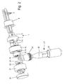
- the device for tapping beverages of the first embodiment in Figs. 1 to 5 has various structural units, which are joined together axially.
- the basic principle is to tap different drinks and drinks with this dispenser to mix with each other.
- a first assembly 1 initially has a total of five leads 2, wherein a supply line for "normal" - possibly cooled - water is provided, a second supply line 2 for carbonated table water and three feeders 2 for different types of syrup. These five supply lines 2 are held in a hose holding piece 3.
- this first unit 1 has a housing 4. On corresponding hose nipples 5 the supply lines 2 are plugged. On the other side, the housing 4 also Nipple 6 on.
- a cylindrical connector body 7 is attached made of ceramic and tightly connected to the nipples 6. The front side of this connection body 7 forms a (first) plane surface 8, in which the feed lines 2 associated openings 9 open.
- a rotatable adjusting ring 10 connects.
- This is a disk-shaped cylinder body 11, the form-fitting in the adjustment ring 10 is held and is rotated when turning the adjusting ring 10.
- the disc-shaped Cylinder body 11 has a total of five through holes 12.
- the usionnfömige Cylinder body 11 is made of ceramic and lies with its (second) plane surface 13 at the (first) flat surface 8 of the terminal body 7 sealingly.
- the to the (second) plane surface 13 opposite surface of the disk-shaped cylinder body 11 is - also - as (fourth) plane surface 14 is formed.
- the dispensing device has a fixed body 15, also made of ceramic, on. Which the (fourth) plane surface 14 of the disk-shaped cylinder body 11 facing (Third) plane surface 16 lies sealingly against the aforementioned (fourth) plane surface 14 of disk-shaped cylinder body 11 at.
- Surface of the fixed body 15 is formed as a (fifth) plane surface 17.
- In the fixed body 15 are channel-like holes 18. These open in two openings. These are in connection with two connection nipples 19 of an output 20 of the dispensing device.
- a device for opening and closing the tap is provided.
- a fixed housing 21 is initially provided.
- a Teflon disk 22 a cylindrical rotary body 23 from Ceramic rotatably mounted.
- the execution of the rotary motion is performed by a rotary ring 24 on the other side of the housing 21.
- the cylindrical rotary body 23 has its the (fifth) plane surface 17 of the fixed body 15 facing (sixth) Planar surface 25 two recess-like recesses 26 on.
- the dispensing device still has a mixing device 27 with a at the output 20 arranged cone 28 and a spout 29.
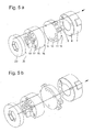
- the disk-shaped one is located Cylinder body 11 in a very specific position, so that the corresponding Through hole 12 of this disc-shaped cylinder body 11 with the associated opening 9 in the first unit 1 with respect to the water supply line 2 is aligned.
- the water passes while passing the disc-shaped cylinder body 11 in the fixed body 15 and from there into the local canal system.
- This channel system is only continuous, when the cylindrical rotary body 23 is in its open position and its Recesses 26 create a continuous channel. In the closed position of the cylindrical Turning body 23, however, is the patency of the corresponding channel interrupted and thus prevented the supply of the beverage in the dispensing device.
- the disc-shaped cylinder body becomes 11 brought by means of the adjusting ring 10 in the desired rotational position, so that the appropriate bottled water supply line 2 is tapped. All other leads 2 are then closed by the plane surface of the disk-shaped cylinder body 11.
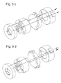
- table water with a first type of syrup (Fig. 5c) or with a second type of syrup (Fig. 5d) are mixed, the disc-shaped cylinder body 11 by means of of the adjusting ring 10 is brought into the appropriate position.
- the appropriate Positioning of the associated through holes 12 in the disk-shaped cylinder body 11th Both the bottled water supply line 2 and the associated syrup supply line 2 are tapped, while the remaining three leads 2 are blocked.
- the two liquids arrive after passing the disk-shaped cylinder body 11 into the fixed body 15 and - with the rotary body 23 open - via the connection nipple 19 in the output 20th the dispensing device.
- the mixing device 27 then the mixing of the table water with the syrup.
- the cylindrical rotary body 23 With a reed contact for detecting the Opening position equipped. With this signal, a release for the upstream Electronic components, such as pumps, water switching valve, etc. granted.
- the dispensing device is designed so that when tapping exclusively of table water the syrup lines are rinsed.
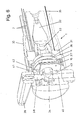
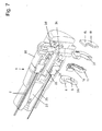
- the second, preferred embodiment of the device for pouring drinks in the Fig. 6 and 7 differs from the first embodiment of Figs. 1 to 5 substantially in terms of feeding the water, while feeding the various Syrup varieties from the basic principle is essentially the same.
- the first unit 1 has a holding part 31 in a housing 30.
- This holding part 31 first opens an axial water supply line 32.
- This water supply line 32 is used for feeding of carbonated table water. It initially widens conically, so as to effect a pressure reduction of the water.
- This is followed by an axial tube 33, which opens in an outlet tap 34 in the form of a ball valve.
- an introduction disc 36 made of ceramic is fixed arranged, in which lead several leads 2 for different syrup types.
- the Front side of this introductory disk 36 forms a first planar surface 8, in which the the supply lines 2 associated openings 9 open.
- the disc-shaped cylinder body 11 is also made of ceramic.
- a subsequent fixed body 15 made of ceramic and the aforementioned Disk-shaped cylinder body 11 is a perpendicular to the central axis up and down movable release disk 37 made of ceramic.
- the whole package the introduction disc 36, the disc-shaped cylinder body 11, the release disc 37 and the fixed body 15 is - as stated - made of ceramic, the mutual contact surfaces are designed as flat surfaces.
- outlet tap 34th in the form of a ball valve. This is the upper side with a shaft 38 with actuating lever 39th connected. Downwards, an outlet line 40 connects.
- an actuating disk 41 On the shaft 38 of the outlet valve 34 is an actuating disk 41 with a oblique groove in the lateral surface. In this oblique groove engages a pin 42 of the release disc 37th
- the disc-shaped cylinder body 11 By means of the disc-shaped cylinder body 11 can be set a specific type of syrup be brought by the disc-shaped cylinder body 11 in the desired rotational position becomes. As a result, the corresponding opening 12 of this disc-shaped aligned Cylinder body 11 with the associated opening 9 in the introduction disc 36. In a certain position of the disk-shaped cylinder body 11 can all supply lines 2 be shut off for the syrup varieties, so that then an admixture of syrup not is possible and only water is tapped.
- the operating lever 39 for the connecting valve 34 is in the closed position in the longitudinal direction of the dispensing device, d. H. in the longitudinal axis.
- the operating lever 39 can then be rotated either 90 degrees to the left or 90 degrees to the right, then whether carbon dioxide-added table water or normal water is desired.
- the desired water enters the outlet conduit 40 below the outlet cock 34.
- the release disk 37 is moved, so that the supply of the desired Syrup variety is released through the ceramic disc package, so that the syrup through the supply system through the outlet conduit 40 and thus supplied to the water and there the syrup is mixed with the water.
Landscapes
- Devices For Dispensing Beverages (AREA)
- Confectionery (AREA)
- Multiple-Way Valves (AREA)
Applications Claiming Priority (2)
| Application Number | Priority Date | Filing Date | Title |
|---|---|---|---|
| DE10352836 | 2003-11-10 | ||
| DE10352836 | 2003-11-10 |
Publications (2)
| Publication Number | Publication Date |
|---|---|
| EP1529752A1 true EP1529752A1 (fr) | 2005-05-11 |
| EP1529752B1 EP1529752B1 (fr) | 2008-07-23 |
Family
ID=34428695
Family Applications (1)
| Application Number | Title | Priority Date | Filing Date |
|---|---|---|---|
| EP04008301A Expired - Lifetime EP1529752B1 (fr) | 2003-11-10 | 2004-04-06 | Vanne pour le mélange de boissons |
Country Status (4)
| Country | Link |
|---|---|
| EP (1) | EP1529752B1 (fr) |
| AT (1) | ATE402116T1 (fr) |
| DE (2) | DE502004007656D1 (fr) |
| WO (1) | WO2005047173A1 (fr) |
Cited By (1)
| Publication number | Priority date | Publication date | Assignee | Title |
|---|---|---|---|---|
| DE102022003950A1 (de) | 2022-10-24 | 2024-04-25 | Günther Gruber | Zapfhahnelement mit einem Flüssigkeitszulauf, Verfahren zur Verwendung eines Zapfhahnelementes sowie Verwendung eines Kompensatorhahnes |
Families Citing this family (1)
| Publication number | Priority date | Publication date | Assignee | Title |
|---|---|---|---|---|
| DE102019205204B4 (de) | 2019-04-11 | 2023-11-30 | BSH Hausgeräte GmbH | Keramikscheibenventil mit kreisrunden Kontaktflächen |
Citations (5)
| Publication number | Priority date | Publication date | Assignee | Title |
|---|---|---|---|---|
| US2408664A (en) * | 1945-05-17 | 1946-10-01 | Ginger Cola Dispenser Inc | Mixing faucet for beverages |
| US2408646A (en) | 1945-08-02 | 1946-10-01 | James R Huntley | Machine tool |
| US2493660A (en) | 1946-02-27 | 1950-01-03 | Charles E Hires Company | Mixing faucet |
| US4794952A (en) | 1987-02-04 | 1989-01-03 | American Standard | Combination mixing valve and appliance valve assembly |
| WO1997047555A1 (fr) | 1996-06-13 | 1997-12-18 | Selector Ltd. | Vanne pour la distribution de plusieurs boissons differentes, et notamment de boissons non alcoolisees |
-
2004
- 2004-04-06 DE DE502004007656T patent/DE502004007656D1/de not_active Expired - Lifetime
- 2004-04-06 EP EP04008301A patent/EP1529752B1/fr not_active Expired - Lifetime
- 2004-04-06 AT AT04008301T patent/ATE402116T1/de not_active IP Right Cessation
- 2004-10-30 DE DE112004002670T patent/DE112004002670D2/de not_active Expired - Fee Related
- 2004-10-30 WO PCT/DE2004/002423 patent/WO2005047173A1/fr not_active Ceased
Patent Citations (5)
| Publication number | Priority date | Publication date | Assignee | Title |
|---|---|---|---|---|
| US2408664A (en) * | 1945-05-17 | 1946-10-01 | Ginger Cola Dispenser Inc | Mixing faucet for beverages |
| US2408646A (en) | 1945-08-02 | 1946-10-01 | James R Huntley | Machine tool |
| US2493660A (en) | 1946-02-27 | 1950-01-03 | Charles E Hires Company | Mixing faucet |
| US4794952A (en) | 1987-02-04 | 1989-01-03 | American Standard | Combination mixing valve and appliance valve assembly |
| WO1997047555A1 (fr) | 1996-06-13 | 1997-12-18 | Selector Ltd. | Vanne pour la distribution de plusieurs boissons differentes, et notamment de boissons non alcoolisees |
Cited By (1)
| Publication number | Priority date | Publication date | Assignee | Title |
|---|---|---|---|---|
| DE102022003950A1 (de) | 2022-10-24 | 2024-04-25 | Günther Gruber | Zapfhahnelement mit einem Flüssigkeitszulauf, Verfahren zur Verwendung eines Zapfhahnelementes sowie Verwendung eines Kompensatorhahnes |
Also Published As
| Publication number | Publication date |
|---|---|
| DE502004007656D1 (de) | 2008-09-04 |
| WO2005047173A1 (fr) | 2005-05-26 |
| DE112004002670D2 (de) | 2006-09-28 |
| EP1529752B1 (fr) | 2008-07-23 |
| ATE402116T1 (de) | 2008-08-15 |
Similar Documents
| Publication | Publication Date | Title |
|---|---|---|
| DE69110630T2 (de) | Ausgabevorrichtungen mit Mehrwegehahn. | |
| EP2692954B1 (fr) | Armature de sortie à plusieurs flux avec sortie pivotante | |
| DE3991109C2 (de) | Mischventil mit Druckausgleichsvorrichtung | |
| EP0309443B1 (fr) | Robinet sanitaire comprenant des plaques parallèles montées dans le bâti | |
| DE69102015T2 (de) | Wassermischventil mit getrennten Betätigungen für die Ausgabe zweier Wasserarten. | |
| DE1550391C3 (de) | Mischventil mit Kugelküken | |
| DE19614653A1 (de) | Ventil | |
| EP1006242A2 (fr) | Système de robinetteries sanitaires | |
| DE19503618C1 (de) | Wasserabgabeventil | |
| EP1319144B1 (fr) | Cartouche pour robinetterie sanitaire | |
| DE102011008804B4 (de) | Sanitärarmatur | |
| EP0653581B1 (fr) | Robinet mitigeur et d'arrêt | |
| DE3109617A1 (de) | Ventil fuer eine sanitaere wassermischarmatur | |
| EP0501953B1 (fr) | Melangeur sanitaire | |
| EP1529752B1 (fr) | Vanne pour le mélange de boissons | |
| EP1061299A2 (fr) | Soupape d'inverseur | |
| DE3112615A1 (de) | Wannenfuell- und brausebatterie | |
| DE3113653A1 (de) | Mischbatterie | |
| DE3990977C2 (de) | Sanitäre Mischarmatur mit zwei Abflüssen und einem Umschaltventil | |
| DE102007010129B4 (de) | Wasserfilter-Kartuschensystem mit kombinierter Verschneideventiltechnik in der Kerze und Einstellvorrichtung im Kopf | |
| EP1484536B1 (fr) | Robinet mélangeur | |
| DE10232506A1 (de) | Zapfhahn für Getränke mit einem Drehschieber | |
| EP1196248A1 (fr) | Tete d'ajutage de commutation pour un appareil de nettoyage haute pression | |
| DE3510908C2 (de) | Einloch-Mischbatterie mit ventilgesteuertem Kaltwasser-Geräteanschluss | |
| DE3509648C2 (de) | Mischbatterie |
Legal Events
| Date | Code | Title | Description |
|---|---|---|---|
| PUAI | Public reference made under article 153(3) epc to a published international application that has entered the european phase |
Free format text: ORIGINAL CODE: 0009012 |
|
| AK | Designated contracting states |
Kind code of ref document: A1 Designated state(s): AT BE BG CH CY CZ DE DK EE ES FI FR GB GR HU IE IT LI LU MC NL PL PT RO SE SI SK TR |
|
| AX | Request for extension of the european patent |
Extension state: AL HR LT LV MK |
|
| 17P | Request for examination filed |
Effective date: 20050513 |
|
| AKX | Designation fees paid |
Designated state(s): AT BE BG CH CY CZ DE DK EE ES FI FR GB GR HU IE IT LI LU MC NL PL PT RO SE SI SK TR |
|
| 17Q | First examination report despatched |
Effective date: 20071017 |
|
| GRAP | Despatch of communication of intention to grant a patent |
Free format text: ORIGINAL CODE: EPIDOSNIGR1 |
|
| GRAS | Grant fee paid |
Free format text: ORIGINAL CODE: EPIDOSNIGR3 |
|
| GRAA | (expected) grant |
Free format text: ORIGINAL CODE: 0009210 |
|
| RAP1 | Party data changed (applicant data changed or rights of an application transferred) |
Owner name: KUNDO XT GMBH |
|
| AK | Designated contracting states |
Kind code of ref document: B1 Designated state(s): AT BE BG CH CY CZ DE DK EE ES FI FR GB GR HU IE IT LI LU MC NL PL PT RO SE SI SK TR |
|
| REG | Reference to a national code |
Ref country code: GB Ref legal event code: FG4D Free format text: NOT ENGLISH |
|
| REG | Reference to a national code |
Ref country code: CH Ref legal event code: EP |
|
| REG | Reference to a national code |
Ref country code: IE Ref legal event code: FG4D Free format text: LANGUAGE OF EP DOCUMENT: GERMAN |
|
| REF | Corresponds to: |
Ref document number: 502004007656 Country of ref document: DE Date of ref document: 20080904 Kind code of ref document: P |
|
| REG | Reference to a national code |
Ref country code: CH Ref legal event code: NV Representative=s name: SCHNEIDER FELDMANN AG PATENT- UND MARKENANWAELTE |
|
| NLV1 | Nl: lapsed or annulled due to failure to fulfill the requirements of art. 29p and 29m of the patents act | ||
| PG25 | Lapsed in a contracting state [announced via postgrant information from national office to epo] |
Ref country code: PT Free format text: LAPSE BECAUSE OF FAILURE TO SUBMIT A TRANSLATION OF THE DESCRIPTION OR TO PAY THE FEE WITHIN THE PRESCRIBED TIME-LIMIT Effective date: 20081223 Ref country code: NL Free format text: LAPSE BECAUSE OF FAILURE TO SUBMIT A TRANSLATION OF THE DESCRIPTION OR TO PAY THE FEE WITHIN THE PRESCRIBED TIME-LIMIT Effective date: 20080723 Ref country code: ES Free format text: LAPSE BECAUSE OF FAILURE TO SUBMIT A TRANSLATION OF THE DESCRIPTION OR TO PAY THE FEE WITHIN THE PRESCRIBED TIME-LIMIT Effective date: 20081103 |
|
| PG25 | Lapsed in a contracting state [announced via postgrant information from national office to epo] |
Ref country code: SI Free format text: LAPSE BECAUSE OF FAILURE TO SUBMIT A TRANSLATION OF THE DESCRIPTION OR TO PAY THE FEE WITHIN THE PRESCRIBED TIME-LIMIT Effective date: 20080723 Ref country code: FI Free format text: LAPSE BECAUSE OF FAILURE TO SUBMIT A TRANSLATION OF THE DESCRIPTION OR TO PAY THE FEE WITHIN THE PRESCRIBED TIME-LIMIT Effective date: 20080723 Ref country code: BG Free format text: LAPSE BECAUSE OF FAILURE TO SUBMIT A TRANSLATION OF THE DESCRIPTION OR TO PAY THE FEE WITHIN THE PRESCRIBED TIME-LIMIT Effective date: 20081023 |
|
| REG | Reference to a national code |
Ref country code: IE Ref legal event code: FD4D |
|
| PG25 | Lapsed in a contracting state [announced via postgrant information from national office to epo] |
Ref country code: EE Free format text: LAPSE BECAUSE OF FAILURE TO SUBMIT A TRANSLATION OF THE DESCRIPTION OR TO PAY THE FEE WITHIN THE PRESCRIBED TIME-LIMIT Effective date: 20080723 Ref country code: DK Free format text: LAPSE BECAUSE OF FAILURE TO SUBMIT A TRANSLATION OF THE DESCRIPTION OR TO PAY THE FEE WITHIN THE PRESCRIBED TIME-LIMIT Effective date: 20080723 Ref country code: IE Free format text: LAPSE BECAUSE OF FAILURE TO SUBMIT A TRANSLATION OF THE DESCRIPTION OR TO PAY THE FEE WITHIN THE PRESCRIBED TIME-LIMIT Effective date: 20080723 |
|
| PG25 | Lapsed in a contracting state [announced via postgrant information from national office to epo] |
Ref country code: SK Free format text: LAPSE BECAUSE OF FAILURE TO SUBMIT A TRANSLATION OF THE DESCRIPTION OR TO PAY THE FEE WITHIN THE PRESCRIBED TIME-LIMIT Effective date: 20080723 Ref country code: RO Free format text: LAPSE BECAUSE OF FAILURE TO SUBMIT A TRANSLATION OF THE DESCRIPTION OR TO PAY THE FEE WITHIN THE PRESCRIBED TIME-LIMIT Effective date: 20080723 |
|
| PLBE | No opposition filed within time limit |
Free format text: ORIGINAL CODE: 0009261 |
|
| STAA | Information on the status of an ep patent application or granted ep patent |
Free format text: STATUS: NO OPPOSITION FILED WITHIN TIME LIMIT |
|
| 26N | No opposition filed |
Effective date: 20090424 |
|
| BERE | Be: lapsed |
Owner name: KUNDO XT G.M.B.H. Effective date: 20090430 |
|
| PG25 | Lapsed in a contracting state [announced via postgrant information from national office to epo] |
Ref country code: SE Free format text: LAPSE BECAUSE OF FAILURE TO SUBMIT A TRANSLATION OF THE DESCRIPTION OR TO PAY THE FEE WITHIN THE PRESCRIBED TIME-LIMIT Effective date: 20081023 |
|
| PG25 | Lapsed in a contracting state [announced via postgrant information from national office to epo] |
Ref country code: MC Free format text: LAPSE BECAUSE OF NON-PAYMENT OF DUE FEES Effective date: 20090430 |
|
| PGFP | Annual fee paid to national office [announced via postgrant information from national office to epo] |
Ref country code: CZ Payment date: 20100324 Year of fee payment: 7 |
|
| PG25 | Lapsed in a contracting state [announced via postgrant information from national office to epo] |
Ref country code: BE Free format text: LAPSE BECAUSE OF NON-PAYMENT OF DUE FEES Effective date: 20090430 Ref country code: PL Free format text: LAPSE BECAUSE OF FAILURE TO SUBMIT A TRANSLATION OF THE DESCRIPTION OR TO PAY THE FEE WITHIN THE PRESCRIBED TIME-LIMIT Effective date: 20080723 |
|
| PGFP | Annual fee paid to national office [announced via postgrant information from national office to epo] |
Ref country code: GB Payment date: 20100324 Year of fee payment: 7 |
|
| PGFP | Annual fee paid to national office [announced via postgrant information from national office to epo] |
Ref country code: FR Payment date: 20100506 Year of fee payment: 7 |
|
| PG25 | Lapsed in a contracting state [announced via postgrant information from national office to epo] |
Ref country code: AT Free format text: LAPSE BECAUSE OF NON-PAYMENT OF DUE FEES Effective date: 20090406 |
|
| PGFP | Annual fee paid to national office [announced via postgrant information from national office to epo] |
Ref country code: IT Payment date: 20100429 Year of fee payment: 7 |
|
| PG25 | Lapsed in a contracting state [announced via postgrant information from national office to epo] |
Ref country code: GR Free format text: LAPSE BECAUSE OF FAILURE TO SUBMIT A TRANSLATION OF THE DESCRIPTION OR TO PAY THE FEE WITHIN THE PRESCRIBED TIME-LIMIT Effective date: 20081024 |
|
| PGFP | Annual fee paid to national office [announced via postgrant information from national office to epo] |
Ref country code: CH Payment date: 20100426 Year of fee payment: 7 |
|
| PG25 | Lapsed in a contracting state [announced via postgrant information from national office to epo] |
Ref country code: LU Free format text: LAPSE BECAUSE OF NON-PAYMENT OF DUE FEES Effective date: 20090406 |
|
| PG25 | Lapsed in a contracting state [announced via postgrant information from national office to epo] |
Ref country code: HU Free format text: LAPSE BECAUSE OF FAILURE TO SUBMIT A TRANSLATION OF THE DESCRIPTION OR TO PAY THE FEE WITHIN THE PRESCRIBED TIME-LIMIT Effective date: 20090124 |
|
| PG25 | Lapsed in a contracting state [announced via postgrant information from national office to epo] |
Ref country code: TR Free format text: LAPSE BECAUSE OF FAILURE TO SUBMIT A TRANSLATION OF THE DESCRIPTION OR TO PAY THE FEE WITHIN THE PRESCRIBED TIME-LIMIT Effective date: 20080723 |
|
| PG25 | Lapsed in a contracting state [announced via postgrant information from national office to epo] |
Ref country code: CY Free format text: LAPSE BECAUSE OF FAILURE TO SUBMIT A TRANSLATION OF THE DESCRIPTION OR TO PAY THE FEE WITHIN THE PRESCRIBED TIME-LIMIT Effective date: 20080723 |
|
| REG | Reference to a national code |
Ref country code: CH Ref legal event code: PL |
|
| GBPC | Gb: european patent ceased through non-payment of renewal fee |
Effective date: 20110406 |
|
| REG | Reference to a national code |
Ref country code: FR Ref legal event code: ST Effective date: 20111230 |
|
| PG25 | Lapsed in a contracting state [announced via postgrant information from national office to epo] |
Ref country code: CH Free format text: LAPSE BECAUSE OF NON-PAYMENT OF DUE FEES Effective date: 20110430 Ref country code: LI Free format text: LAPSE BECAUSE OF NON-PAYMENT OF DUE FEES Effective date: 20110430 Ref country code: CZ Free format text: LAPSE BECAUSE OF NON-PAYMENT OF DUE FEES Effective date: 20110406 Ref country code: FR Free format text: LAPSE BECAUSE OF NON-PAYMENT OF DUE FEES Effective date: 20110502 |
|
| PG25 | Lapsed in a contracting state [announced via postgrant information from national office to epo] |
Ref country code: GB Free format text: LAPSE BECAUSE OF NON-PAYMENT OF DUE FEES Effective date: 20110406 Ref country code: IT Free format text: LAPSE BECAUSE OF NON-PAYMENT OF DUE FEES Effective date: 20110406 |
|
| PGFP | Annual fee paid to national office [announced via postgrant information from national office to epo] |
Ref country code: DE Payment date: 20130116 Year of fee payment: 10 |
|
| REG | Reference to a national code |
Ref country code: DE Ref legal event code: R119 Ref document number: 502004007656 Country of ref document: DE |
|
| REG | Reference to a national code |
Ref country code: DE Ref legal event code: R119 Ref document number: 502004007656 Country of ref document: DE Effective date: 20141101 |
|
| PG25 | Lapsed in a contracting state [announced via postgrant information from national office to epo] |
Ref country code: DE Free format text: LAPSE BECAUSE OF NON-PAYMENT OF DUE FEES Effective date: 20141101 |