EP1529695A1 - Fahreradaptives Kollisionswarnsystem - Google Patents
Fahreradaptives Kollisionswarnsystem Download PDFInfo
- Publication number
- EP1529695A1 EP1529695A1 EP04077772A EP04077772A EP1529695A1 EP 1529695 A1 EP1529695 A1 EP 1529695A1 EP 04077772 A EP04077772 A EP 04077772A EP 04077772 A EP04077772 A EP 04077772A EP 1529695 A1 EP1529695 A1 EP 1529695A1
- Authority
- EP
- European Patent Office
- Prior art keywords
- driver
- data
- ares
- max
- attitude level
- Prior art date
- Legal status (The legal status is an assumption and is not a legal conclusion. Google has not performed a legal analysis and makes no representation as to the accuracy of the status listed.)
- Granted
Links
Images


Classifications
-
- B—PERFORMING OPERATIONS; TRANSPORTING
- B60—VEHICLES IN GENERAL
- B60W—CONJOINT CONTROL OF VEHICLE SUB-UNITS OF DIFFERENT TYPE OR DIFFERENT FUNCTION; CONTROL SYSTEMS SPECIALLY ADAPTED FOR HYBRID VEHICLES; ROAD VEHICLE DRIVE CONTROL SYSTEMS FOR PURPOSES NOT RELATED TO THE CONTROL OF A PARTICULAR SUB-UNIT
- B60W50/00—Details of control systems for road vehicle drive control not related to the control of a particular sub-unit, e.g. process diagnostic or vehicle driver interfaces
- B60W50/08—Interaction between the driver and the control system
- B60W50/14—Means for informing the driver, warning the driver or prompting a driver intervention
- B60W50/16—Tactile feedback to the driver, e.g. vibration or force feedback to the driver on the steering wheel or the accelerator pedal
-
- B—PERFORMING OPERATIONS; TRANSPORTING
- B60—VEHICLES IN GENERAL
- B60K—ARRANGEMENT OR MOUNTING OF PROPULSION UNITS OR OF TRANSMISSIONS IN VEHICLES; ARRANGEMENT OR MOUNTING OF PLURAL DIVERSE PRIME-MOVERS IN VEHICLES; AUXILIARY DRIVES FOR VEHICLES; INSTRUMENTATION OR DASHBOARDS FOR VEHICLES; ARRANGEMENTS IN CONNECTION WITH COOLING, AIR INTAKE, GAS EXHAUST OR FUEL SUPPLY OF PROPULSION UNITS IN VEHICLES
- B60K31/00—Vehicle fittings, acting on a single sub-unit only, for automatically controlling vehicle speed, i.e. preventing speed from exceeding an arbitrarily established velocity or maintaining speed at a particular velocity, as selected by the vehicle operator
- B60K31/0008—Vehicle fittings, acting on a single sub-unit only, for automatically controlling vehicle speed, i.e. preventing speed from exceeding an arbitrarily established velocity or maintaining speed at a particular velocity, as selected by the vehicle operator including means for detecting potential obstacles in vehicle path
-
- B—PERFORMING OPERATIONS; TRANSPORTING
- B60—VEHICLES IN GENERAL
- B60T—VEHICLE BRAKE CONTROL SYSTEMS OR PARTS THEREOF; BRAKE CONTROL SYSTEMS OR PARTS THEREOF, IN GENERAL; ARRANGEMENT OF BRAKING ELEMENTS ON VEHICLES IN GENERAL; PORTABLE DEVICES FOR PREVENTING UNWANTED MOVEMENT OF VEHICLES; VEHICLE MODIFICATIONS TO FACILITATE COOLING OF BRAKES
- B60T2220/00—Monitoring, detecting driver behaviour; Signalling thereof; Counteracting thereof
- B60T2220/02—Driver type; Driving style; Driver adaptive features
-
- B—PERFORMING OPERATIONS; TRANSPORTING
- B60—VEHICLES IN GENERAL
- B60W—CONJOINT CONTROL OF VEHICLE SUB-UNITS OF DIFFERENT TYPE OR DIFFERENT FUNCTION; CONTROL SYSTEMS SPECIALLY ADAPTED FOR HYBRID VEHICLES; ROAD VEHICLE DRIVE CONTROL SYSTEMS FOR PURPOSES NOT RELATED TO THE CONTROL OF A PARTICULAR SUB-UNIT
- B60W50/00—Details of control systems for road vehicle drive control not related to the control of a particular sub-unit, e.g. process diagnostic or vehicle driver interfaces
- B60W2050/0001—Details of the control system
- B60W2050/0019—Control system elements or transfer functions
- B60W2050/0022—Gains, weighting coefficients or weighting functions
- B60W2050/0025—Transfer function weighting factor
-
- B—PERFORMING OPERATIONS; TRANSPORTING
- B60—VEHICLES IN GENERAL
- B60W—CONJOINT CONTROL OF VEHICLE SUB-UNITS OF DIFFERENT TYPE OR DIFFERENT FUNCTION; CONTROL SYSTEMS SPECIALLY ADAPTED FOR HYBRID VEHICLES; ROAD VEHICLE DRIVE CONTROL SYSTEMS FOR PURPOSES NOT RELATED TO THE CONTROL OF A PARTICULAR SUB-UNIT
- B60W50/00—Details of control systems for road vehicle drive control not related to the control of a particular sub-unit, e.g. process diagnostic or vehicle driver interfaces
- B60W2050/0001—Details of the control system
- B60W2050/0019—Control system elements or transfer functions
- B60W2050/0028—Mathematical models, e.g. for simulation
- B60W2050/0029—Mathematical model of the driver
-
- B—PERFORMING OPERATIONS; TRANSPORTING
- B60—VEHICLES IN GENERAL
- B60W—CONJOINT CONTROL OF VEHICLE SUB-UNITS OF DIFFERENT TYPE OR DIFFERENT FUNCTION; CONTROL SYSTEMS SPECIALLY ADAPTED FOR HYBRID VEHICLES; ROAD VEHICLE DRIVE CONTROL SYSTEMS FOR PURPOSES NOT RELATED TO THE CONTROL OF A PARTICULAR SUB-UNIT
- B60W50/00—Details of control systems for road vehicle drive control not related to the control of a particular sub-unit, e.g. process diagnostic or vehicle driver interfaces
- B60W50/08—Interaction between the driver and the control system
- B60W50/14—Means for informing the driver, warning the driver or prompting a driver intervention
- B60W2050/143—Alarm means
-
- B—PERFORMING OPERATIONS; TRANSPORTING
- B60—VEHICLES IN GENERAL
- B60W—CONJOINT CONTROL OF VEHICLE SUB-UNITS OF DIFFERENT TYPE OR DIFFERENT FUNCTION; CONTROL SYSTEMS SPECIALLY ADAPTED FOR HYBRID VEHICLES; ROAD VEHICLE DRIVE CONTROL SYSTEMS FOR PURPOSES NOT RELATED TO THE CONTROL OF A PARTICULAR SUB-UNIT
- B60W2540/00—Input parameters relating to occupants
- B60W2540/30—Driving style
Definitions
- the present invention relates to car safety system, particularly collision warning system capable of alerting a driver of a collision potential.
- Automatic collision warning systems for a vehicle operate based on input data relating to the mental and physical condition of the driver including his behavior during adverse road conditions.
- the input data can be used by the systems to generate output control affecting timing of audio, visual, and tactile collision warnings.
- the state of the art for present collision warning systems may require an input from the operator of the vehicle by way of a dash-mounted control knob.
- the precise degree of this input is the operator's best judgment as to whether they are an aggressive or conservative driver.
- a mis-interpretation of this characteristic, or simply a mis-adjustment, can have severe consequences on the performance of the collision warning system.
- Another known danger avoidance system includes a driver monitoring system for monitoring the driver's physical condition and behavior such as the driver's line of sight, the blinking of the driver, the blood pressure, the pulse count, and the body temperature.
- the data from the driver monitoring system coupled with the data from other monitoring systems such as the ambient condition monitoring system and vehicle condition monitoring system are used as the basis to prompt danger recognition that effectuates the danger avoidance system to give warning.
- the shortcoming of the system includes warning given too early for a driver who is aggressive in driving behavior, who tends to drive fast and keeps a short distance from the leading vehicle. On the other hand, the warning may be too late for a driver who is conservative in driving behavior, who tends to drive slowly and keeps a long distance from the leading car.
- An error in one direction causes false alarms which are feared to be the primary cause of the above types of systems being disabled, and then of no benefit at all. And an error in the other direction may allow the system to alert so late as to be useless, and thereby possibly aiding in the potential accident and creating a liability situation.
- the present invention provides systems and methods for issuing collision warnings with individualized timing responsive to individual driver's behavior or attitude level.
- the method of the present invention comprises the steps of: determining a driving style including a driver attitude level, determining timing for issuing a warning based on the determined driving style, and issuing a warning based on the determined timing.
- the driver attitude level is determined based on data related to the driver's actions in plurality of driving conditions.
- the parameters associated with the actions may be measured and transformed mathematically by applying pre-determined algorithm to obtain parametric values representing the driver attitude level.
- the method comprises the steps of: collecting data corresponding to at least one parametric model (PM) relating to driver attitude; determining parametric model (PM) value distribution for each PM; and determining an individual driver attitude based on individual driver data and the parametric (PM) value distribution for the at least one parametric model (PM).
- PM parametric model
- the parametric model (PM) value distribution may be determined by applying pre-determined algorithm corresponding to each of the PMs, such as calculating percentile values representing the PM value distribution.
- the method may include the steps of: determining an average value for each PM value distribution; and determining a parametric-specific attitude level for each PM by mapping the average value for each PM value distribution to a pre-determined scale specific to each PM.
- the value mapping may be based on a scale of 0 to 10, wherein 0 represents most conservative driver attitude level, and 10 represents most aggressive driver attitude level.
- the data may be collected under a plurality of driving conditions, and by at least one sensor integrated to an automobile.
- the method includes at least one of the following parametric models (PMs): host vehicle velocity ( hostv ) PM for capturing how fast a driver drives in an absence of a lead vehicle, acceleration ( host-acc ) PM for capturing acceleration profile as a function of hostv , and drive's allowable response time ( T ares ) PM for capturing how much time the driver is allowed to react to an extreme stop condition without colliding with a lead vehicle.
- PMs parametric models
- the present invention further provides a system for forewarning a driver of potential collision comprising: a first device for collecting data corresponding to driver attitude; and a second device connected to the first device for determining driver attitude level from the collected data.
- the second device may comprise software for enabling storing of the collected data, and a processor for processing the data according to pre-determined algorithm to determine driver attitude level.
- the first device may be capable of collecting data corresponding to driving actions in a plurality of driving conditions and from a plurality of drivers.
- the second device further comprises software for enabling selection of data according to pre-determined criteria; and the processor is capable of processing the selected data.
- the system further comprises a third device functionally connected to the second device for determining timing for warning based on the driver attitude level, and issuing a warning according to the precise timing.
- the third device may comprise software for enabling determination of the timing for warning and an alarm for producing a perceptible signal.
- the alarm may include an audio, a visual or a tactile alarm.
- One object of the invention is to provide a forewarning system that is capable of issuing warning to a driver at precise time to ensure safety.
- Another object of the invention is to provide a forewarning system that issues warnings according to the driver's attitude.
- Yet another object of the invention is to provide a system for determining drivers' attitude that can be integrated to existing forewarning components.
- the present invention provides systems and methods for forewarning a driver of a potential collision.
- the warning is issued at timing adapted to the driver's driving style or attitude level.
- the driving style may be determined by the driver's behavior or acts in response to certain driving conditions or occurrences.
- the driving style may also be characterized in terms of attitude , which ranges from conservative to aggressive.
- driver models are created to represent the driver's behavior which may be described in the terms of what the driver usually does based on a given set of parameters and how the driver reacts to driving situations. For example, with a given current velocity and following distance, the driver tends to slow down or speed up.
- attitude level can be estimated with regard to how aggressive this driver is, relative to other drivers.
- a confidence level may be calculated based on the quantity of data learned. These attitude and confidence levels may be processed within a collision warning system to appropriately adjust warning timing according to the driver's driving style.
- the driver behavior may change, depending on driving conditions, for example, weather condition, traffic condition, and the time of day. Behavior during car-following is likely to be different from that during lane changing. Examples of various driving conditions are shown in Table 1. Examples of various driving conditions: Condition Type Alternative State Scenario Accelerating: -while moving/-from stopping Decelerating: -while moving/-to stopping Changing lane/Passing/Cutting off/Parking/Reversing Lane Straight/Curve/Winding/Up hill/Down hill/Intersection/Corner Traffic Car in front/Car on left/Car on right/Car in rear Combinations/No cars Road Dry/Wet/Icy Weather Clear/Raining/Snowing/Foggy/Windy Time of Day Day/Night/Dusk/Dawn MMM Devices Off/On Mode Normal/ACC engaged
- the parameters such as velocity, acceleration, yaw rate, lane position, etc., which may be selected to represent the driver behavior, may also vary from one driving condition to another.
- driver behavior may change over a period of time.
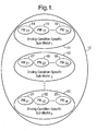
- the driver model should have the following characteristics: 1) customized to individual driver, 2) adaptive to change of driving style for a) different driving conditions and b) over time, 3) comprised of various driving-condition-specific sub-models, 4) each driving-condition-specific sub-model is generated by processing data, obtained from an identified driving condition, and collected from monitored parameters, 5) set of monitored parameters may vary depending on driving conditions, and 6) different driving conditions may, if possible, share the same sub-model in order to minimize the number of sub-models.
- Driver model 10 comprises of a plurality of driving-condition-specific sub-models 11-13. Each of these sub-models 11-13 contains multiple sub parametric models. For example, in driving-condition-specific sub-model 11, there are “p" number of PMs 14-16, in driving-condition-specific sub-model 12, there are “q” number of PMs 17-19, and in driving condition specific 13, there are “r” number of PMs 21-23.
- a PM represents data distribution of a monitored parameter such as acceleration, velocity, etc.
- PM Value distribution can be transformed by applying Learning Algorithm or Memory-Based Learning (MBL) with percentile.
- MBL can be used as a predictor or classifier, where the answer to a query is a function of answers to past training examples, which are similar to the current query. All past training examples are stored in memory.
- the memory can be a one or multi-dimensional array depending on the number of training input states.
- MBL 30 may be utilized for learning driving behavior. MBL 30 may be used to learn what the driver usually does, and how the driver reacts to specific situations. For these purposes, past driving data of relevant parameters (for instance, velocity or acceleration) are stored in the memory, representing the data distribution of those parameters, and the past reactions of the driver to various driving situations are used to train the system to learn the driver response for any given situation.
- Training space 31, represented by cube 36 contains data corresponding to three driving conditions 33-35.
- the driving conditions 33-35 include current lead vehicle velocity 34, represented by the x-axis, current range (following distance) 35 represented by the y-axis, and current host vehicle velocity 33 represented by the z-axis.
- the driver reaction is characterized as the host vehicle velocity value at t seconds after the given situation occurred.
- Output data (learned data) may be determined using a variety of pre-determined algorithm to transform the input data distribution. For example, output data distribution 32 for host vehicle velocity is derived from the input data distribution as values of percentiles 38.
- Process 40 can be used to create PMV 47.
- First raw data 42 for a specific parametric model is collected.
- the collection of raw data 42 may be accomplished through a variety of traditional means such as sensors for detecting automobile's or driver's performance, or other driving conditions as listed in TABLE 1 shown hereinabove.
- sensor 41 may be mounted on or integrated with an appropriate mechanism of a vehicle to capture raw data during a driver operating the vehicle.
- the collected raw data 42 are subject to step of data selection 43, in which a portion of raw data 42 that does not meet certain selection criteria is discarded in order to eliminate noisy and meaningless data. Depending on measured parameters, the selection criteria should capture the aggression level of the driver.
- the selected data 44 are then modified by applying pre-determined learning algorithm to generate learned data 46. For example, selected data 44 may be sorted and the values of the percentiles from 0 to 100 are calculated and stored in the memory. These percentile values, or PMV representing the data distribution of the measured parameter.
- only one PM may be used to determine the driver attitude.
- the PM used is acceleration PM
- the selected data based on criteria specific to acceleration PM that are collected and stored in each bin of the memory is first sorted (e.g. in ascending order). Then, a learning algorithm (calculation of acceleration values base on percentile values from 0 to 100) will yield learned data distribution which represents PMVs of measured acceleration distribution.
- a value of x for the percentile y means that in y% of the selected data, the driver's acceleration is less than x .
- a plurality of PMs may be used to determine the driver attitude.
- the examples of possible PMs are listed in Table 2.
- the driver attitude may be derived from PM values by following the steps shown in flow chart in Figure 4.
- the PMV or the percentile values of each PM 52 stored in the memory are processed through step 53 to obtain the average of the PM values, which are mapped to a scale between 0 (most conservative) and 10 (most aggressive) to determine the driver attitude level, relative to other drivers.
- the PM values may be averaged in many ways depending on the parameter and its data distribution. Basically, the averaged PM values should represent the aggression level of the driver. In order to map the scale appropriately, an individual averaged PM value must be compared to a range of data obtained from general population. Each attitude level derived from a single PM is called parameter-specific attitude level.
- the plurality of parameter-specific attitude levels 54 obtained from a plurality of PMV 52 may be combined.
- the parameter-specific attitude levels 54 may be suitably weighted in step 55 in order to estimate the overall driver attitude.
- the parameter's degree of relevance to driver attitude determines the weight. The higher the degree of relevance, the higher the weight is.
- the overall driver attitude level can be sent to a warning system, particularly electronically to be processed as in step 61 so that the warning system determines the timing to issue warning signals in step 62 adaptive and optimal to an individual driving style.
- the overall process for forewarning a driver of a potential collision may be conducted by a combined system 50, which comprises "Driver Radar Enhanced Adaptive Modeling (DREAM) System” 51 for determining the driver attitude as described hereinabove, and a “Forward Collision-Warning (FCW) System” 60 for determining timing and issuing warning signals corresponding to driver attitude levels.
- the FCW system 60 may include any commercially available system that can perform timing determination and issuing warning.
- three PMs are used to determine the driver attitude. These PMs include host vehicle velocity (hostv ), acceleration (host_acc ), and driver's allowable response-time T ares.
- the hostv PM is used for measuring driver attitude in host vehicle velocity. This PM captures how fast the driver drives in the absence of a lead vehicle (data selection criterion 1). Velocities under a specified speed, for example, 55 mph, are clipped out (data selection criterion 2) since they are significantly lower than a legal speed limit on the highway. This PM is measured only when there is no lane change (data selection criterion 3).
- the selected hostv data are sorted and the parameter values for the percentiles from 0 to 100 are calculated. These percentile values are stored in the memory, representing the hostv PM.
- the host_acc PM is used for measuring driver attitude is the acceleration of host vehicle (host_acc ).
- the model captures acceleration profile as a function of hostv . Therefore, the memory contains hostv bins ranging from 2 to 90 mph with bin size of 1 mph. Accelerations below a specified acceleration rate, for example, 0.8 mph /s (data selection criterion 1), are considered to be too small to be meaningful and, therefore, may be clipped out.
- This PM is measured only when there is no lane change (data selection criterion 2).
- Each of the selected host_acc data is stored in the appropriate hostv bin. Then the data in each hostv bin may be sorted and their percentile values are calculated.
- the T ares PM is used to determine how much time the driver is allowed to react to an extreme stop condition without colliding with the lead vehicle.
- the driver who usually follows the lead vehicle with short T ares , is likely to be an aggressive driver since he/she has less time to deal with such situation.
- This T ares estimated from host vehicle velocity, lead vehicle velocity, and range, can be obtained by solving a second order polynomial equation (1) shown below. where a max is the maximum acceleration, d max is the maximum deceleration, J max is the maximum allowed jerk, and sum ad is the summation of a max and d max .
- An extreme stop condition is the condition where, at the moment the lead vehicle driver initiates a stop maneuver, the lead vehicle is assumed to be at full deceleration ( d max ) with initial lead velocity leadv (0) while the host vehicle is at highest acceleration ( a max ) with initial host velocity hostv (0).
- Driver's reaction time ( T res ) is the time period from the point where the stop maneuver commences until the host vehicle driver notices it and reacts to the situation by applying a brake with d max . It is assumed that the maximum allowable jerk during deceleration from a max to d max is J max . It is also assumed that both vehicles have the same a max , d max , and J max , and these parameters are all constant.
- T res which is estimated from the other parameters in equation (1), is, in fact, not the actual driver's response time. But it is the time that the driver is allowed to react in order to avoid colliding with the lead vehicle under the extreme stop condition.
- T res obtained from equation (1) is renamed to "driver's allowable response-time" ( T ares ).
- the driver usually follows the lead vehicle (data selection criterion 1) with a short allowable response-time, he/she would have less time to deal with the extreme stop condition. Thus, the shorter the allowable response-time is, the more aggressive the driver is.
- the data are selected when there is no lane change (data selection criterion 2), leadv - hostv ⁇ 5 mph for 1 second (data selection criterion 3), and T ares ⁇ T ares + (2 * std ( T ares )), where T ares is an approximate average and std ( T ares ) is an approximate standard deviation, of all selected T ares data (data selection criterion 4).
- the third criterion assures that T ares data, which are not caused by the host vehicle driver's intention, are eliminated. While the forth criterion removes T ares data which are too high.
- T ares values of the percentiles from 0 to 100 of the selected data in each hostv bin are calculated and stored in the memory.
- Table 3 summarizes the training state inputs, output data distribution, and data selection criteria of all three PMs listed in this specific embodiment. Summary of data criteria for all three PMs Parametric Model Training input state Output data distribution Data selection criteria Host vehicle speed - hostv 1) Lead vehicle non-exist 2) hostv > 55 mph 3) Not lane changing Acceleration hostv host_acc 1) host_acc > 0.8 mph / s 2) Not lane changing Driver's allowable response time hostv Tares 1) Lead vehicle non-exist 2) Not lane changing 3) leadv-hostv ⁇ 5mph for 1 second 4) Tares ⁇ Tares +(2*std( Tares ))
- Figures 5A-5B Figure 5A shows output data distribution inside host vehicle velocity PM of Driver A and B.
- Figure 5B shows data distribution inside acceleration PM of Driver A
- Figure 5C shows data distribution inside acceleration PM of Driver B
- Figure 5D shows data distribution inside T ares PM of Driver A
- Figure 5E shows data distribution inside Tares PM of Driver B.
- the percentile values for the real drivers A and B, and simulated drivers C, D, E, and F were also generated and further processed as described hereinbelow.
- the overall driver attitude level was determined according to the following steps:
- Step (1) Obtaining an average value of each PM.
- the average value of the output data stored in each PM was calculated. This average value represents the driver's aggression level, based on a single parameter. A method to average the data varied, depending on the parameter. For T ares and acceleration PMs, the lowest and highest five percents of data were thrown out. Only the values of the percentiles between 5 and 95 were averaged. For the host vehicle velocity PM, only the hostv values of the percentiles between 80 and 95 were averaged. The average values for all parameters for all drivers were shown in Table 6 hereinbelow.
- Step (2) Calculating parameter-specific attitude level
- a global min-max (minimum to maximum) range of each parameter was set first. This min-max range was an outcome from an extensive study on various drivers to determine the minimum and maximum values of each parameter. This min-max range was mapped to scales between 0 (most conservative) and 10 (most aggressive). For the present study, the global min-max range of each parameter was assumed to be as shown in Table 5. It should be noted that the shorter T ares , the higher the scale was (opposite to the other two parameters).
- Step (3) Estimating overall attitude level of the driver
- a weight for each parameter was determined prior to computing the overall attitude level.
- the weights for all parameters were set as shown in Table 5.
- the overall attitude level can be calculated. The results are shown in Table 6.
- the exemplary embodiments of the current method are focused on driving on highway and car following case only (without lane changing)
- initial experimental results show that the method of the present invention may be adapted to provide useful data (attitude level) about an individual driver for any warning system to appropriately adjust the warning timing to suit his/her driving style.
- the timing for forewarning may be adjusted to the driver's attitude in different driving conditions as shown in the examples listed in Table 2.
- FCW Forward Collision Warning
- a speed profile can be created to match individual driving styles. This profile is used to control the speed of the vehicle during the Resume operation, providing more comfort/safety to the driver. In some cases, the speed profile of extremely aggressive drivers may be modified to ensure safety.
- Adaptive cruise control is an extension of the conventional cruise control.
- the system uses a sensor (radar or laser) to detect the front vehicles.
- radar radar or laser
- the vehicle When the traffic is clear, it operates in the same manner as the conventional cruise control - maintaining the set speed. However, when the vehicle encounters traffic, the vehicle slows down and maintains a safety distance to the lead vehicle. Once the traffic is clear again, the vehicle speeds up to the set speed.
- TTC Time to Collide
- the system can automatically adjust the safety distance according to individual driving style - providing more comfort and the feeling as if the driver drives the car him/herself.
- the knob or button is no longer required.
- the driving style information can be used to adjust the rate of the change of the speed when the vehicle needs to slow down (when approaching the traffic) or to speed up (when the traffic is clear).
- device assembly 70 of the present invention which may be incorporated into a vehicle control system, comprises first device 71 for collecting data, and second device 73 for determining driver attitude level connected functionally to first device 71.
- First device 71 may include a plurality of sensors 72 capable of detecting driver actions in various situations and driving conditions.
- Second device 73 may include software 74 enabling storing of data received from sensors 72, and processor 75 for processing the stored data.
- Processor 75 can apply pre-determined algorithm to the stored data to generate parametric model values which relate to driver attitude as described hereinabove.
- Processor 75 is capable of determining attitude levels of a plurality of drivers from corresponding parametric model values.
- Device assembly 70 may also comprise third device 76 which may have software 77 for enabling determination of timing of warning responsive to a driver attitude level and enabling alarm 78 to issue any variety of signals to warn the driver of a potential collision.
- Alarm 78 may produce an audio, a visual, or a tactile signal or sign or any combination thereof. Differing signals or signs may represent different types of potential collision. The driver can respond appropriately to a specific warning signal.
- third device 76 may include software 79 for enabling a determination of rate of change of speed in terms of acceleration and deceleration responsive to the driver attitude level; and acceleration and deceleration control 80 for adjusting the rate of change of speed in terms of acceleration and deceleration based on the determined rate of change.
- third device 76 may contain software 81 enabling a determination of a safety distance from another vehicle based on the driver attitude level, and a distance control 82 for maintaining the determined safety distance.
- the distance control 82 may include an alarm 83 for warning the driver when the vehicle gets too close to the other vehicle, violating the safety distance. The driver may then act appropriately to keep the vehicle at the determined safety distance.
Landscapes
- Engineering & Computer Science (AREA)
- Automation & Control Theory (AREA)
- Transportation (AREA)
- Mechanical Engineering (AREA)
- Human Computer Interaction (AREA)
- Chemical & Material Sciences (AREA)
- Combustion & Propulsion (AREA)
- Traffic Control Systems (AREA)
- Emergency Alarm Devices (AREA)
Applications Claiming Priority (2)
| Application Number | Priority Date | Filing Date | Title |
|---|---|---|---|
| US684757 | 1996-07-22 | ||
| US10/684,757 US7206697B2 (en) | 2003-10-14 | 2003-10-14 | Driver adaptive collision warning system |
Publications (2)
| Publication Number | Publication Date |
|---|---|
| EP1529695A1 true EP1529695A1 (de) | 2005-05-11 |
| EP1529695B1 EP1529695B1 (de) | 2007-06-20 |
Family
ID=34423017
Family Applications (1)
| Application Number | Title | Priority Date | Filing Date |
|---|---|---|---|
| EP04077772A Expired - Lifetime EP1529695B1 (de) | 2003-10-14 | 2004-10-06 | Fahreradaptives Kollisionswarnsystem |
Country Status (4)
| Country | Link |
|---|---|
| US (2) | US7206697B2 (de) |
| EP (1) | EP1529695B1 (de) |
| AT (1) | ATE365121T1 (de) |
| DE (1) | DE602004007083T2 (de) |
Cited By (3)
| Publication number | Priority date | Publication date | Assignee | Title |
|---|---|---|---|---|
| US8972103B2 (en) | 2013-03-19 | 2015-03-03 | Ford Global Technologies, Llc | Method of building and using local map of vehicle drive path |
| US9037340B2 (en) | 2013-03-19 | 2015-05-19 | Ford Global Technologies, Llc | System and method for modifying adaptive cruise control set points |
| US20180017402A1 (en) * | 2016-07-15 | 2018-01-18 | Tata Consultancy Services Limited | Method and system for vehicle speed profile generation |
Families Citing this family (120)
| Publication number | Priority date | Publication date | Assignee | Title |
|---|---|---|---|---|
| US5910854A (en) | 1993-02-26 | 1999-06-08 | Donnelly Corporation | Electrochromic polymeric solid films, manufacturing electrochromic devices using such solid films, and processes for making such solid films and devices |
| US5668663A (en) | 1994-05-05 | 1997-09-16 | Donnelly Corporation | Electrochromic mirrors and devices |
| US6891563B2 (en) * | 1996-05-22 | 2005-05-10 | Donnelly Corporation | Vehicular vision system |
| US6124886A (en) | 1997-08-25 | 2000-09-26 | Donnelly Corporation | Modular rearview mirror assembly |
| US6326613B1 (en) | 1998-01-07 | 2001-12-04 | Donnelly Corporation | Vehicle interior mirror assembly adapted for containing a rain sensor |
| US6172613B1 (en) | 1998-02-18 | 2001-01-09 | Donnelly Corporation | Rearview mirror assembly incorporating vehicle information display |
| US8294975B2 (en) | 1997-08-25 | 2012-10-23 | Donnelly Corporation | Automotive rearview mirror assembly |
| US8288711B2 (en) | 1998-01-07 | 2012-10-16 | Donnelly Corporation | Interior rearview mirror system with forwardly-viewing camera and a control |
| US6445287B1 (en) | 2000-02-28 | 2002-09-03 | Donnelly Corporation | Tire inflation assistance monitoring system |
| US6477464B2 (en) | 2000-03-09 | 2002-11-05 | Donnelly Corporation | Complete mirror-based global-positioning system (GPS) navigation solution |
| US6329925B1 (en) | 1999-11-24 | 2001-12-11 | Donnelly Corporation | Rearview mirror assembly with added feature modular display |
| US6693517B2 (en) | 2000-04-21 | 2004-02-17 | Donnelly Corporation | Vehicle mirror assembly communicating wirelessly with vehicle accessories and occupants |
| US7167796B2 (en) | 2000-03-09 | 2007-01-23 | Donnelly Corporation | Vehicle navigation system for use with a telematics system |
| WO2001064481A2 (en) | 2000-03-02 | 2001-09-07 | Donnelly Corporation | Video mirror systems incorporating an accessory module |
| US7195381B2 (en) | 2001-01-23 | 2007-03-27 | Donnelly Corporation | Vehicle interior LED lighting system |
| US7370983B2 (en) | 2000-03-02 | 2008-05-13 | Donnelly Corporation | Interior mirror assembly with display |
| US7255451B2 (en) | 2002-09-20 | 2007-08-14 | Donnelly Corporation | Electro-optic mirror cell |
| US7581859B2 (en) | 2005-09-14 | 2009-09-01 | Donnelly Corp. | Display device for exterior rearview mirror |
| DE10103401A1 (de) * | 2001-01-26 | 2002-08-01 | Daimler Chrysler Ag | Gefahrenabwendungssystem für ein Fahrzeug |
| US6918674B2 (en) | 2002-05-03 | 2005-07-19 | Donnelly Corporation | Vehicle rearview mirror system |
| WO2003105099A1 (en) | 2002-06-06 | 2003-12-18 | Donnelly Corporation | Interior rearview mirror system with compass |
| US7329013B2 (en) | 2002-06-06 | 2008-02-12 | Donnelly Corporation | Interior rearview mirror system with compass |
| US7310177B2 (en) | 2002-09-20 | 2007-12-18 | Donnelly Corporation | Electro-optic reflective element assembly |
| US7274501B2 (en) | 2002-09-20 | 2007-09-25 | Donnelly Corporation | Mirror reflective element assembly |
| NO333526B1 (no) * | 2003-06-12 | 2013-07-01 | Vestas Wind Sys As | System for å avverge kollisjon mellom luftfartøy og et hinder |
| US7446924B2 (en) | 2003-10-02 | 2008-11-04 | Donnelly Corporation | Mirror reflective element assembly including electronic component |
| US7308341B2 (en) | 2003-10-14 | 2007-12-11 | Donnelly Corporation | Vehicle communication system |
| JP3915766B2 (ja) * | 2003-10-15 | 2007-05-16 | 株式会社デンソー | 運転支援装置 |
| DE10356307A1 (de) * | 2003-11-28 | 2005-06-23 | Robert Bosch Gmbh | Verfahren und Vorrichtung zur Warnung des Fahrers eines Kraftfahrzeugs |
| KR100569009B1 (ko) * | 2003-12-30 | 2006-04-07 | 현대자동차주식회사 | 차량용 정보 시스템의 사용성 평가 시스템 |
| DE102004004918B4 (de) * | 2004-01-31 | 2024-03-14 | Zf Cv Systems Hannover Gmbh | Verfahren zur Kollisions-Warnung bei einem Kraftfahrzeug |
| JP4172434B2 (ja) * | 2004-07-30 | 2008-10-29 | トヨタ自動車株式会社 | 車間距離制御装置 |
| US7974778B2 (en) * | 2004-09-17 | 2011-07-05 | Honda Motor Co., Ltd. | Vehicular control object determination system and vehicular travel locus estimation system |
| DE102004051963A1 (de) * | 2004-10-25 | 2006-05-04 | Robert Bosch Gmbh | Verfahren zur Fahrerunterstützung |
| DE102004052519A1 (de) * | 2004-10-29 | 2006-05-04 | Robert Bosch Gmbh | Vorrichtung zur Vermeidung einer Kollision |
| EP1883855B1 (de) * | 2005-05-16 | 2011-07-20 | Donnelly Corporation | Fahrzeugspiegelanordnung mit zeichen am reflektierenden teil |
| DE102005026065A1 (de) * | 2005-06-07 | 2006-12-21 | Robert Bosch Gmbh | Adaptiver Geschwindigkeitsregler mit situationsabhängiger Dynamikanpassung |
| US7561032B2 (en) * | 2005-09-26 | 2009-07-14 | Gm Global Technology Operations, Inc. | Selectable lane-departure warning system and method |
| CN101535087B (zh) | 2005-11-01 | 2013-05-15 | 唐纳利公司 | 具有显示装置的内部后视镜 |
| DE102006008981A1 (de) * | 2006-02-23 | 2007-08-30 | Siemens Ag | Assistenzsystem zur Unterstützung eines Fahrers |
| US20080183360A1 (en) * | 2006-05-08 | 2008-07-31 | Yizhen Zhang | Vehicle collision avoidance and warning |
| US20080042814A1 (en) * | 2006-08-18 | 2008-02-21 | Motorola, Inc. | Mode sensitive vehicle hazard warning apparatuses and method |
| US7609150B2 (en) * | 2006-08-18 | 2009-10-27 | Motorola, Inc. | User adaptive vehicle hazard warning apparatuses and method |
| GB0625726D0 (en) * | 2006-12-22 | 2007-02-07 | Trw Ltd | Method of operating a vehicle |
| US7979199B2 (en) | 2007-01-10 | 2011-07-12 | Honeywell International Inc. | Method and system to automatically generate a clearance request to deviate from a flight plan |
| TWI318185B (en) * | 2007-07-31 | 2009-12-11 | Univ Nat Taiwan Science Tech | Online monitoring method of driver state and system thereof |
| CN101458078A (zh) * | 2007-12-10 | 2009-06-17 | 鸿富锦精密工业(深圳)有限公司 | 一种汽车防撞系统及方法 |
| US8154418B2 (en) | 2008-03-31 | 2012-04-10 | Magna Mirrors Of America, Inc. | Interior rearview mirror system |
| JP5332356B2 (ja) * | 2008-07-08 | 2013-11-06 | 日産自動車株式会社 | 車両用運転支援装置 |
| US20100020170A1 (en) | 2008-07-24 | 2010-01-28 | Higgins-Luthman Michael J | Vehicle Imaging System |
| US20100152950A1 (en) * | 2008-12-15 | 2010-06-17 | Gm Global Technology Operations, Inc. | Adaptive vehicle control system with driving style recognition based on vehicle stopping |
| US8055427B2 (en) * | 2008-12-18 | 2011-11-08 | GM Global Technology Operations LLC | Method and apparatus for speed-limit following cruise control |
| US8411245B2 (en) * | 2009-02-06 | 2013-04-02 | Gentex Corporation | Multi-display mirror system and method for expanded view around a vehicle |
| US8237909B2 (en) * | 2009-02-06 | 2012-08-07 | Gentex Corporation | Vehicular rearview mirror assembly including integrated backlighting for a liquid crystal display (LCD) |
| EP2473871B1 (de) | 2009-09-01 | 2015-03-11 | Magna Mirrors Of America, Inc. | Abbildungs- und anzeigesystem für fahrzeuge |
| KR101331054B1 (ko) * | 2010-05-13 | 2013-11-19 | 한국전자통신연구원 | 도로노면정보 및 통계적 교통상황을 고려한 안전속도 산정방법 및 그 장치 |
| EP2407356A1 (de) * | 2010-07-17 | 2012-01-18 | Valeo Schalter und Sensoren GmbH | Verfahren zum eigenständigen Bremsen eines Kraftfahrzeugs und autonomes Bremssystem für ein Kraftfahrzeug |
| DE102010050167B4 (de) * | 2010-10-30 | 2012-10-25 | Audi Ag | Verfahren und Vorrichtung zur Bestimmung eines plausiblen Fahrstreifens zur Führung eines Fahrzeugs sowie Kraftwagen |
| DE102010051203B4 (de) * | 2010-11-12 | 2022-07-28 | Zf Active Safety Gmbh | Verfahren zur Erkennung von kritischen Fahrsituationen von Lastkraft- oder Personenkraftwagen, insbesondere zur Vermeidung von Kollisionen |
| US9264672B2 (en) | 2010-12-22 | 2016-02-16 | Magna Mirrors Of America, Inc. | Vision display system for vehicle |
| US10169822B2 (en) | 2011-12-02 | 2019-01-01 | Spireon, Inc. | Insurance rate optimization through driver behavior monitoring |
| US8510200B2 (en) | 2011-12-02 | 2013-08-13 | Spireon, Inc. | Geospatial data based assessment of driver behavior |
| US8635018B2 (en) | 2012-02-03 | 2014-01-21 | International Business Machines Corporation | Managing a driver profile |
| US9007198B2 (en) | 2012-11-02 | 2015-04-14 | Toyota Motor Engineering & Manufacturing North America, Inc. | Adaptive Actuator interface for active driver warning |
| US9779379B2 (en) | 2012-11-05 | 2017-10-03 | Spireon, Inc. | Container verification through an electrical receptacle and plug associated with a container and a transport vehicle of an intermodal freight transport system |
| US8933802B2 (en) | 2012-11-05 | 2015-01-13 | Spireon, Inc. | Switch and actuator coupling in a chassis of a container associated with an intermodal freight transport system |
| DE102013214383A1 (de) | 2013-07-23 | 2015-01-29 | Robert Bosch Gmbh | Verfahren und Vorrichtung zum Bereitstellen eines Kollisionsignals hinsichtlich einer Fahrzeugkollision, Verfahren und Vorrichtung zum Verwalten von Kollisionsdaten hinsichtlich Fahrzeugkollisionen sowie Verfahren und Vorrichtung zum Steuern zumindest einer Kollisionsschutzeinrichtung eines Fahrzeugs |
| US9779449B2 (en) | 2013-08-30 | 2017-10-03 | Spireon, Inc. | Veracity determination through comparison of a geospatial location of a vehicle with a provided data |
| DE202013008112U1 (de) * | 2013-09-11 | 2014-12-12 | GM Global Technology Operations LLC (n. d. Gesetzen des Staates Delaware) | Fahrerassistenzsystem für ein Kraftfahrzeug |
| EP2848488B2 (de) * | 2013-09-12 | 2022-04-13 | Volvo Car Corporation | Verfahren und Einrichtung zur Übergabewarnung in einem Fahrzeug mit autonomer Fahrfähigkeit |
| US20150186991A1 (en) | 2013-12-31 | 2015-07-02 | David M. Meyer | Creditor alert when a vehicle enters an impound lot |
| US9266536B2 (en) * | 2014-01-17 | 2016-02-23 | Fca Us Llc | Adaptive cruise control system and method |
| EP2913239B1 (de) * | 2014-02-28 | 2019-06-19 | Volvo Car Corporation | Verfahren und einheit zur abstandsregelung |
| US9734685B2 (en) | 2014-03-07 | 2017-08-15 | State Farm Mutual Automobile Insurance Company | Vehicle operator emotion management system and method |
| US9135803B1 (en) | 2014-04-17 | 2015-09-15 | State Farm Mutual Automobile Insurance Company | Advanced vehicle operator intelligence system |
| US9260059B2 (en) | 2014-04-25 | 2016-02-16 | Robert Bosch Gmbh | False warning reduction using location data |
| US10354330B1 (en) | 2014-05-20 | 2019-07-16 | State Farm Mutual Automobile Insurance Company | Autonomous feature use monitoring and insurance pricing |
| US10599155B1 (en) | 2014-05-20 | 2020-03-24 | State Farm Mutual Automobile Insurance Company | Autonomous vehicle operation feature monitoring and evaluation of effectiveness |
| US10373259B1 (en) | 2014-05-20 | 2019-08-06 | State Farm Mutual Automobile Insurance Company | Fully autonomous vehicle insurance pricing |
| US11669090B2 (en) | 2014-05-20 | 2023-06-06 | State Farm Mutual Automobile Insurance Company | Autonomous vehicle operation feature monitoring and evaluation of effectiveness |
| US9972054B1 (en) | 2014-05-20 | 2018-05-15 | State Farm Mutual Automobile Insurance Company | Accident fault determination for autonomous vehicles |
| US10319039B1 (en) | 2014-05-20 | 2019-06-11 | State Farm Mutual Automobile Insurance Company | Accident fault determination for autonomous vehicles |
| US10185999B1 (en) | 2014-05-20 | 2019-01-22 | State Farm Mutual Automobile Insurance Company | Autonomous feature use monitoring and telematics |
| US9786154B1 (en) | 2014-07-21 | 2017-10-10 | State Farm Mutual Automobile Insurance Company | Methods of facilitating emergency assistance |
| JP6387452B2 (ja) * | 2014-08-05 | 2018-09-05 | 深▲せん▼市元征科技股▲ふん▼有限公司 | 運転行為ガイダンス情報の生成方法、装置及びシステム |
| US10026324B2 (en) | 2014-11-04 | 2018-07-17 | Honeywell International Inc. | Systems and methods for enhanced adoptive validation of ATC clearance requests |
| US10241509B1 (en) | 2014-11-13 | 2019-03-26 | State Farm Mutual Automobile Insurance Company | Autonomous vehicle control assessment and selection |
| US9321441B1 (en) * | 2014-11-19 | 2016-04-26 | Robert Bosch Gmbh | GPS based learned control event prediction |
| WO2016103460A1 (ja) * | 2014-12-26 | 2016-06-30 | 横浜ゴム株式会社 | 衝突回避システム |
| US9551788B2 (en) | 2015-03-24 | 2017-01-24 | Jim Epler | Fleet pan to provide measurement and location of a stored transport item while maximizing space in an interior cavity of a trailer |
| JP6363558B2 (ja) * | 2015-06-02 | 2018-07-25 | 株式会社デンソー | 車両制御装置、及び車両制御方法 |
| US10589741B2 (en) * | 2015-08-27 | 2020-03-17 | Ford Global Technologies, Llc | Enhanced collision avoidance |
| US11107365B1 (en) | 2015-08-28 | 2021-08-31 | State Farm Mutual Automobile Insurance Company | Vehicular driver evaluation |
| RU2706859C2 (ru) * | 2015-09-28 | 2019-11-21 | ФОРД ГЛОУБАЛ ТЕКНОЛОДЖИЗ, ЭлЭлСи | Система и способ обнаружения препятствий |
| US10701202B2 (en) * | 2015-11-10 | 2020-06-30 | Lenovo Enterprise Solutions (Singapore) Pte. Ltd. | Control of notifications on a mobile communication device based on driving conditions |
| US11441916B1 (en) | 2016-01-22 | 2022-09-13 | State Farm Mutual Automobile Insurance Company | Autonomous vehicle trip routing |
| US10395332B1 (en) | 2016-01-22 | 2019-08-27 | State Farm Mutual Automobile Insurance Company | Coordinated autonomous vehicle automatic area scanning |
| US10324463B1 (en) | 2016-01-22 | 2019-06-18 | State Farm Mutual Automobile Insurance Company | Autonomous vehicle operation adjustment based upon route |
| US9940834B1 (en) | 2016-01-22 | 2018-04-10 | State Farm Mutual Automobile Insurance Company | Autonomous vehicle application |
| US10503168B1 (en) | 2016-01-22 | 2019-12-10 | State Farm Mutual Automotive Insurance Company | Autonomous vehicle retrieval |
| US11242051B1 (en) | 2016-01-22 | 2022-02-08 | State Farm Mutual Automobile Insurance Company | Autonomous vehicle action communications |
| US11719545B2 (en) | 2016-01-22 | 2023-08-08 | Hyundai Motor Company | Autonomous vehicle component damage and salvage assessment |
| US10134278B1 (en) | 2016-01-22 | 2018-11-20 | State Farm Mutual Automobile Insurance Company | Autonomous vehicle application |
| DE102016201939B4 (de) | 2016-02-09 | 2025-09-04 | Volkswagen Aktiengesellschaft | Verfahren und System zur Verbesserung der Wahrnehmung bei Kollisionsvermeidungssystemen |
| CN105912814A (zh) * | 2016-05-05 | 2016-08-31 | 苏州京坤达汽车电子科技有限公司 | 智能驾驶车辆换道决策模型 |
| CN106886211B (zh) * | 2017-02-20 | 2019-07-19 | 北京奇虎科技有限公司 | 汽车安全测试等级的确定方法及装置 |
| US11273836B2 (en) * | 2017-12-18 | 2022-03-15 | Plusai, Inc. | Method and system for human-like driving lane planning in autonomous driving vehicles |
| CN109017602B (zh) * | 2018-07-13 | 2023-08-18 | 吉林大学 | 一种基于人体姿态识别的自适应中控台及其控制方法 |
| CN109087323A (zh) * | 2018-07-25 | 2018-12-25 | 武汉大学 | 一种基于精细cad模型的图像车辆三维姿态估计方法 |
| CN109002041B (zh) * | 2018-08-09 | 2021-03-19 | 北京智行者科技有限公司 | 一种车辆避障方法 |
| US11620494B2 (en) | 2018-09-26 | 2023-04-04 | Allstate Insurance Company | Adaptable on-deployment learning platform for driver analysis output generation |
| US11422551B2 (en) * | 2018-12-27 | 2022-08-23 | Intel Corporation | Technologies for providing a cognitive capacity test for autonomous driving |
| CN110456801B (zh) * | 2019-08-29 | 2022-05-17 | 重庆长安汽车股份有限公司 | 一种自动驾驶汽车的跟车控制方法、装置及汽车 |
| CN110956810B (zh) * | 2019-10-28 | 2021-08-20 | 南京市德赛西威汽车电子有限公司 | 一种基于rsu和v2x的复杂道路前向预警方法 |
| KR102911845B1 (ko) * | 2019-12-17 | 2026-01-15 | 현대자동차주식회사 | 차량의 자율주행 제어장치 및 그 방법 |
| KR20220089762A (ko) * | 2020-12-21 | 2022-06-29 | 현대모비스 주식회사 | 차량 충돌 방지 시스템 및 그 방법 |
| JP7766227B2 (ja) | 2021-08-20 | 2025-11-10 | ジェンテックス コーポレイション | 照明アセンブリ及び照明アセンブリを有する照射システム |
| CN114613131B (zh) * | 2022-03-01 | 2023-03-28 | 北京航空航天大学 | 一种基于安全裕度的个性化前向碰撞预警方法 |
| US20240217345A1 (en) * | 2022-12-29 | 2024-07-04 | Hyundai Kefico Corporation | Driving pattern regenerative braking method of vehicle |
| WO2025165897A1 (en) * | 2024-01-30 | 2025-08-07 | NetraDyne, Inc. | Autonomous alert adjustment based on driver feedback |
Citations (4)
| Publication number | Priority date | Publication date | Assignee | Title |
|---|---|---|---|---|
| EP0637525A2 (de) * | 1993-08-06 | 1995-02-08 | Bayerische Motoren Werke Aktiengesellschaft | Verfahren zum Vermeiden von Kollisionen von Kraftfahrzeugen |
| DE4437678A1 (de) * | 1994-10-21 | 1996-05-02 | Telefunken Microelectron | Verfahren zur Abstandsregelung von Kraftfahrzeugen |
| DE10132386A1 (de) * | 2001-07-06 | 2003-01-16 | Volkswagen Ag | Fahrerassistenzsystem |
| WO2004005092A1 (de) * | 2002-07-05 | 2004-01-15 | Continental Teves Ag & Co.Ohg | Fahrerassistenzsystem und vorrichtung zur bremsenregelung |
Family Cites Families (8)
| Publication number | Priority date | Publication date | Assignee | Title |
|---|---|---|---|---|
| JPH06150199A (ja) * | 1992-11-13 | 1994-05-31 | Mitsubishi Electric Corp | 車両予防安全装置 |
| US5983161A (en) * | 1993-08-11 | 1999-11-09 | Lemelson; Jerome H. | GPS vehicle collision avoidance warning and control system and method |
| US6768944B2 (en) * | 2002-04-09 | 2004-07-27 | Intelligent Technologies International, Inc. | Method and system for controlling a vehicle |
| US6161071A (en) * | 1999-03-12 | 2000-12-12 | Navigation Technologies Corporation | Method and system for an in-vehicle computing architecture |
| US6366207B1 (en) * | 2000-02-04 | 2002-04-02 | Michael Murphy | Device for modifying vehicle operator driving behavior |
| US6560525B1 (en) * | 2002-01-02 | 2003-05-06 | Ford Global Technologies, Llc | Integrated queue assist and adaptive cruise control |
| US6708099B2 (en) * | 2002-01-17 | 2004-03-16 | Ford Global Technologies, Llc | Stop and go adaptive cruise control system |
| US6873911B2 (en) * | 2002-02-01 | 2005-03-29 | Nissan Motor Co., Ltd. | Method and system for vehicle operator assistance improvement |
-
2003
- 2003-10-14 US US10/684,757 patent/US7206697B2/en not_active Expired - Lifetime
-
2004
- 2004-10-06 DE DE602004007083T patent/DE602004007083T2/de not_active Expired - Lifetime
- 2004-10-06 AT AT04077772T patent/ATE365121T1/de not_active IP Right Cessation
- 2004-10-06 EP EP04077772A patent/EP1529695B1/de not_active Expired - Lifetime
-
2007
- 2007-02-06 US US11/702,824 patent/US7302344B2/en not_active Expired - Lifetime
Patent Citations (4)
| Publication number | Priority date | Publication date | Assignee | Title |
|---|---|---|---|---|
| EP0637525A2 (de) * | 1993-08-06 | 1995-02-08 | Bayerische Motoren Werke Aktiengesellschaft | Verfahren zum Vermeiden von Kollisionen von Kraftfahrzeugen |
| DE4437678A1 (de) * | 1994-10-21 | 1996-05-02 | Telefunken Microelectron | Verfahren zur Abstandsregelung von Kraftfahrzeugen |
| DE10132386A1 (de) * | 2001-07-06 | 2003-01-16 | Volkswagen Ag | Fahrerassistenzsystem |
| WO2004005092A1 (de) * | 2002-07-05 | 2004-01-15 | Continental Teves Ag & Co.Ohg | Fahrerassistenzsystem und vorrichtung zur bremsenregelung |
Cited By (5)
| Publication number | Priority date | Publication date | Assignee | Title |
|---|---|---|---|---|
| US8972103B2 (en) | 2013-03-19 | 2015-03-03 | Ford Global Technologies, Llc | Method of building and using local map of vehicle drive path |
| US9037340B2 (en) | 2013-03-19 | 2015-05-19 | Ford Global Technologies, Llc | System and method for modifying adaptive cruise control set points |
| US20180017402A1 (en) * | 2016-07-15 | 2018-01-18 | Tata Consultancy Services Limited | Method and system for vehicle speed profile generation |
| EP3272612A1 (de) * | 2016-07-15 | 2018-01-24 | Tata Consultancy Services Limited | Verfahren und system zur fahrzeuggeschwindigkeitsprofilerzeugung |
| AU2021202991B2 (en) * | 2016-07-15 | 2023-02-23 | Tata Consultancy Services Limited | Method and system for vehicle speed profile generation |
Also Published As
| Publication number | Publication date |
|---|---|
| US7206697B2 (en) | 2007-04-17 |
| DE602004007083D1 (de) | 2007-08-02 |
| DE602004007083T2 (de) | 2008-02-14 |
| US7302344B2 (en) | 2007-11-27 |
| ATE365121T1 (de) | 2007-07-15 |
| EP1529695B1 (de) | 2007-06-20 |
| US20070198191A1 (en) | 2007-08-23 |
| US20050080565A1 (en) | 2005-04-14 |
Similar Documents
| Publication | Publication Date | Title |
|---|---|---|
| US7302344B2 (en) | Driver adaptive collision warning system | |
| US12351152B2 (en) | Emergency braking for autonomous vehicles | |
| US20190071100A1 (en) | Autonomous driving adjustment method, apparatus, and system | |
| CN107117179B (zh) | 基于乘员注意的自主控制 | |
| CN107121979B (zh) | 自主置信控制 | |
| US9180890B2 (en) | Smart adaptive cruise control | |
| US10518782B2 (en) | Driving characteristics estimating device and drive assisting system | |
| CN112699721B (zh) | 离开道路扫视时间的情境相关调整 | |
| US10754335B2 (en) | Automated driving system | |
| JP5900448B2 (ja) | 運転支援装置 | |
| US20170248953A1 (en) | Autonomous peril control | |
| US20170247040A1 (en) | Autonomous vehicle control transitioning | |
| US20150025731A1 (en) | Interactive automated driving system | |
| US20200081436A1 (en) | Policy generation device and vehicle | |
| JP7415471B2 (ja) | 運転評価装置、運転評価システム、車載装置、車外評価装置、および運転評価プログラム | |
| US20200086873A1 (en) | Monitoring driver movement | |
| JP2022189809A (ja) | 車両内において使用される機械学習モデルを再構成するための超音波システム及び方法 | |
| CN114103966A (zh) | 一种辅助驾驶的控制方法、装置和系统 | |
| JP2022149751A (ja) | 車両の運転支援装置 | |
| CN111483458B (zh) | 一种动力系统控制方法及装置 | |
| KR20150066308A (ko) | 운전자 운행 상태 판단 장치 및 그 방법 | |
| JP2022189811A (ja) | 機械学習アルゴリズム内において使用される機械学習分類器をチューニングするための超音波システム及び方法 | |
| US20240409121A1 (en) | Autonomous driving system | |
| JP2018094294A (ja) | 状態推定システム | |
| JP2022189810A (ja) | 機械学習アルゴリズムを使用して障害物を分類するための超音波システム及び方法 |
Legal Events
| Date | Code | Title | Description |
|---|---|---|---|
| PUAI | Public reference made under article 153(3) epc to a published international application that has entered the european phase |
Free format text: ORIGINAL CODE: 0009012 |
|
| AK | Designated contracting states |
Kind code of ref document: A1 Designated state(s): AT BE BG CH CY CZ DE DK EE ES FI FR GB GR HU IE IT LI LU MC NL PL PT RO SE SI SK TR |
|
| AX | Request for extension of the european patent |
Extension state: AL HR LT LV MK |
|
| 17P | Request for examination filed |
Effective date: 20051111 |
|
| AKX | Designation fees paid |
Designated state(s): AT BE BG CH CY CZ DE DK EE ES FI FR GB GR HU IE IT LI LU MC NL PL PT RO SE SI SK TR |
|
| 17Q | First examination report despatched |
Effective date: 20060831 |
|
| GRAP | Despatch of communication of intention to grant a patent |
Free format text: ORIGINAL CODE: EPIDOSNIGR1 |
|
| GRAS | Grant fee paid |
Free format text: ORIGINAL CODE: EPIDOSNIGR3 |
|
| GRAA | (expected) grant |
Free format text: ORIGINAL CODE: 0009210 |
|
| AK | Designated contracting states |
Kind code of ref document: B1 Designated state(s): AT BE BG CH CY CZ DE DK EE ES FI FR GB GR HU IE IT LI LU MC NL PL PT RO SE SI SK TR |
|
| PG25 | Lapsed in a contracting state [announced via postgrant information from national office to epo] |
Ref country code: CH Free format text: LAPSE BECAUSE OF FAILURE TO SUBMIT A TRANSLATION OF THE DESCRIPTION OR TO PAY THE FEE WITHIN THE PRESCRIBED TIME-LIMIT Effective date: 20070620 Ref country code: LI Free format text: LAPSE BECAUSE OF FAILURE TO SUBMIT A TRANSLATION OF THE DESCRIPTION OR TO PAY THE FEE WITHIN THE PRESCRIBED TIME-LIMIT Effective date: 20070620 |
|
| REG | Reference to a national code |
Ref country code: GB Ref legal event code: FG4D |
|
| REG | Reference to a national code |
Ref country code: CH Ref legal event code: EP |
|
| REG | Reference to a national code |
Ref country code: IE Ref legal event code: FG4D |
|
| REF | Corresponds to: |
Ref document number: 602004007083 Country of ref document: DE Date of ref document: 20070802 Kind code of ref document: P |
|
| PG25 | Lapsed in a contracting state [announced via postgrant information from national office to epo] |
Ref country code: SE Free format text: LAPSE BECAUSE OF FAILURE TO SUBMIT A TRANSLATION OF THE DESCRIPTION OR TO PAY THE FEE WITHIN THE PRESCRIBED TIME-LIMIT Effective date: 20070920 |
|
| PG25 | Lapsed in a contracting state [announced via postgrant information from national office to epo] |
Ref country code: AT Free format text: LAPSE BECAUSE OF FAILURE TO SUBMIT A TRANSLATION OF THE DESCRIPTION OR TO PAY THE FEE WITHIN THE PRESCRIBED TIME-LIMIT Effective date: 20070620 Ref country code: PL Free format text: LAPSE BECAUSE OF FAILURE TO SUBMIT A TRANSLATION OF THE DESCRIPTION OR TO PAY THE FEE WITHIN THE PRESCRIBED TIME-LIMIT Effective date: 20070620 |
|
| NLV1 | Nl: lapsed or annulled due to failure to fulfill the requirements of art. 29p and 29m of the patents act | ||
| REG | Reference to a national code |
Ref country code: CH Ref legal event code: PL |
|
| PG25 | Lapsed in a contracting state [announced via postgrant information from national office to epo] |
Ref country code: BE Free format text: LAPSE BECAUSE OF FAILURE TO SUBMIT A TRANSLATION OF THE DESCRIPTION OR TO PAY THE FEE WITHIN THE PRESCRIBED TIME-LIMIT Effective date: 20070620 |
|
| PG25 | Lapsed in a contracting state [announced via postgrant information from national office to epo] |
Ref country code: NL Free format text: LAPSE BECAUSE OF FAILURE TO SUBMIT A TRANSLATION OF THE DESCRIPTION OR TO PAY THE FEE WITHIN THE PRESCRIBED TIME-LIMIT Effective date: 20070620 Ref country code: BG Free format text: LAPSE BECAUSE OF FAILURE TO SUBMIT A TRANSLATION OF THE DESCRIPTION OR TO PAY THE FEE WITHIN THE PRESCRIBED TIME-LIMIT Effective date: 20070920 Ref country code: PT Free format text: LAPSE BECAUSE OF FAILURE TO SUBMIT A TRANSLATION OF THE DESCRIPTION OR TO PAY THE FEE WITHIN THE PRESCRIBED TIME-LIMIT Effective date: 20071120 Ref country code: ES Free format text: LAPSE BECAUSE OF FAILURE TO SUBMIT A TRANSLATION OF THE DESCRIPTION OR TO PAY THE FEE WITHIN THE PRESCRIBED TIME-LIMIT Effective date: 20071001 Ref country code: SI Free format text: LAPSE BECAUSE OF FAILURE TO SUBMIT A TRANSLATION OF THE DESCRIPTION OR TO PAY THE FEE WITHIN THE PRESCRIBED TIME-LIMIT Effective date: 20070620 Ref country code: CZ Free format text: LAPSE BECAUSE OF FAILURE TO SUBMIT A TRANSLATION OF THE DESCRIPTION OR TO PAY THE FEE WITHIN THE PRESCRIBED TIME-LIMIT Effective date: 20070620 |
|
| EN | Fr: translation not filed | ||
| PG25 | Lapsed in a contracting state [announced via postgrant information from national office to epo] |
Ref country code: SK Free format text: LAPSE BECAUSE OF FAILURE TO SUBMIT A TRANSLATION OF THE DESCRIPTION OR TO PAY THE FEE WITHIN THE PRESCRIBED TIME-LIMIT Effective date: 20070620 |
|
| PLBE | No opposition filed within time limit |
Free format text: ORIGINAL CODE: 0009261 |
|
| STAA | Information on the status of an ep patent application or granted ep patent |
Free format text: STATUS: NO OPPOSITION FILED WITHIN TIME LIMIT |
|
| PG25 | Lapsed in a contracting state [announced via postgrant information from national office to epo] |
Ref country code: IT Free format text: LAPSE BECAUSE OF FAILURE TO SUBMIT A TRANSLATION OF THE DESCRIPTION OR TO PAY THE FEE WITHIN THE PRESCRIBED TIME-LIMIT Effective date: 20070620 Ref country code: GR Free format text: LAPSE BECAUSE OF FAILURE TO SUBMIT A TRANSLATION OF THE DESCRIPTION OR TO PAY THE FEE WITHIN THE PRESCRIBED TIME-LIMIT Effective date: 20070921 Ref country code: DK Free format text: LAPSE BECAUSE OF FAILURE TO SUBMIT A TRANSLATION OF THE DESCRIPTION OR TO PAY THE FEE WITHIN THE PRESCRIBED TIME-LIMIT Effective date: 20070620 |
|
| 26N | No opposition filed |
Effective date: 20080325 |
|
| PG25 | Lapsed in a contracting state [announced via postgrant information from national office to epo] |
Ref country code: RO Free format text: LAPSE BECAUSE OF FAILURE TO SUBMIT A TRANSLATION OF THE DESCRIPTION OR TO PAY THE FEE WITHIN THE PRESCRIBED TIME-LIMIT Effective date: 20070620 Ref country code: MC Free format text: LAPSE BECAUSE OF NON-PAYMENT OF DUE FEES Effective date: 20071031 |
|
| PG25 | Lapsed in a contracting state [announced via postgrant information from national office to epo] |
Ref country code: FR Free format text: LAPSE BECAUSE OF FAILURE TO SUBMIT A TRANSLATION OF THE DESCRIPTION OR TO PAY THE FEE WITHIN THE PRESCRIBED TIME-LIMIT Effective date: 20080222 |
|
| PG25 | Lapsed in a contracting state [announced via postgrant information from national office to epo] |
Ref country code: IE Free format text: LAPSE BECAUSE OF NON-PAYMENT OF DUE FEES Effective date: 20071008 |
|
| PG25 | Lapsed in a contracting state [announced via postgrant information from national office to epo] |
Ref country code: EE Free format text: LAPSE BECAUSE OF FAILURE TO SUBMIT A TRANSLATION OF THE DESCRIPTION OR TO PAY THE FEE WITHIN THE PRESCRIBED TIME-LIMIT Effective date: 20070620 |
|
| PG25 | Lapsed in a contracting state [announced via postgrant information from national office to epo] |
Ref country code: FI Free format text: LAPSE BECAUSE OF FAILURE TO SUBMIT A TRANSLATION OF THE DESCRIPTION OR TO PAY THE FEE WITHIN THE PRESCRIBED TIME-LIMIT Effective date: 20070620 |
|
| GBPC | Gb: european patent ceased through non-payment of renewal fee |
Effective date: 20081006 |
|
| PG25 | Lapsed in a contracting state [announced via postgrant information from national office to epo] |
Ref country code: CY Free format text: LAPSE BECAUSE OF FAILURE TO SUBMIT A TRANSLATION OF THE DESCRIPTION OR TO PAY THE FEE WITHIN THE PRESCRIBED TIME-LIMIT Effective date: 20070620 |
|
| PG25 | Lapsed in a contracting state [announced via postgrant information from national office to epo] |
Ref country code: LU Free format text: LAPSE BECAUSE OF NON-PAYMENT OF DUE FEES Effective date: 20071006 |
|
| PG25 | Lapsed in a contracting state [announced via postgrant information from national office to epo] |
Ref country code: TR Free format text: LAPSE BECAUSE OF FAILURE TO SUBMIT A TRANSLATION OF THE DESCRIPTION OR TO PAY THE FEE WITHIN THE PRESCRIBED TIME-LIMIT Effective date: 20070620 Ref country code: HU Free format text: LAPSE BECAUSE OF FAILURE TO SUBMIT A TRANSLATION OF THE DESCRIPTION OR TO PAY THE FEE WITHIN THE PRESCRIBED TIME-LIMIT Effective date: 20071221 |
|
| PG25 | Lapsed in a contracting state [announced via postgrant information from national office to epo] |
Ref country code: GB Free format text: LAPSE BECAUSE OF NON-PAYMENT OF DUE FEES Effective date: 20081006 |
|
| REG | Reference to a national code |
Ref country code: DE Ref legal event code: R082 Ref document number: 602004007083 Country of ref document: DE Representative=s name: GRUENECKER, KINKELDEY, STOCKMAIR & SCHWANHAEUS, DE Ref country code: DE Ref legal event code: R082 Ref document number: 602004007083 Country of ref document: DE Representative=s name: GRUENECKER PATENT- UND RECHTSANWAELTE PARTG MB, DE |
|
| REG | Reference to a national code |
Ref country code: DE Ref legal event code: R081 Ref document number: 602004007083 Country of ref document: DE Owner name: SAMSUNG ELECTRONICS CO., LTD., SUWON-SI, KR Free format text: FORMER OWNER: DELPHI TECHNOLOGIES, INC., TROY, MICH., US Effective date: 20150219 Ref country code: DE Ref legal event code: R082 Ref document number: 602004007083 Country of ref document: DE Representative=s name: GRUENECKER PATENT- UND RECHTSANWAELTE PARTG MB, DE Effective date: 20150219 |
|
| PGFP | Annual fee paid to national office [announced via postgrant information from national office to epo] |
Ref country code: DE Payment date: 20230920 Year of fee payment: 20 |
|
| REG | Reference to a national code |
Ref country code: DE Ref legal event code: R071 Ref document number: 602004007083 Country of ref document: DE |