EP1529689A1 - Procédé d'affichage du trajectoire d'un essieux tracté de véhicule - Google Patents
Procédé d'affichage du trajectoire d'un essieux tracté de véhicule Download PDFInfo
- Publication number
- EP1529689A1 EP1529689A1 EP04024700A EP04024700A EP1529689A1 EP 1529689 A1 EP1529689 A1 EP 1529689A1 EP 04024700 A EP04024700 A EP 04024700A EP 04024700 A EP04024700 A EP 04024700A EP 1529689 A1 EP1529689 A1 EP 1529689A1
- Authority
- EP
- European Patent Office
- Prior art keywords
- vehicle part
- towed
- image capture
- towing
- curve
- Prior art date
- Legal status (The legal status is an assumption and is not a legal conclusion. Google has not performed a legal analysis and makes no representation as to the accuracy of the status listed.)
- Withdrawn
Links
Images
Classifications
-
- B—PERFORMING OPERATIONS; TRANSPORTING
- B60—VEHICLES IN GENERAL
- B60R—VEHICLES, VEHICLE FITTINGS, OR VEHICLE PARTS, NOT OTHERWISE PROVIDED FOR
- B60R1/00—Optical viewing arrangements; Real-time viewing arrangements for drivers or passengers using optical image capturing systems, e.g. cameras or video systems specially adapted for use in or on vehicles
- B60R1/02—Rear-view mirror arrangements
- B60R1/025—Rear-view mirror arrangements comprising special mechanical means for correcting the field of view in relation to particular driving conditions, e.g. change of lane; scanning mirrors
Definitions
- the invention relates to a method for displaying the travel path a towed by a towing vehicle part of a vehicle Axis of a towed vehicle part at a cornering of the vehicle, in which the angle of a Tracking device detected and the detected Image is displayed to the driver.
- From DE 298 18 214 U1 is a side view system for vehicles, in particular for trucks, which became known at least one vehicle-mounted, rear-facing Video camera, at least one screen for playback the signals of the video camera in the field of vision of the driver as well an adjustment device for each camera.
- the video camera by a NachGermanautomatik is supplemented. This can make the video camera proportional be moved with the steering angle to the outside.
- the object of the present invention is therefore a method to provide with the track of the towed Axis (s) are reliably displayed to the driver can.
- This object is achieved by a method of solved at the beginning, in which the position and / or the drag curve of the trailing axle is determined from this the necessary tracking of the viewing angle of the image capture device for recording the route of the towed Axis determined and the viewing angle accordingly is tracked.
- Imaging devices provided so that when cornering, both to the left and to the right, the towed axle (s) of the towed vehicle part can be detected.
- the position of the dragged Axis can be determined absolutely or in relation to a reference point. Such a relative position can for example, with respect to the position of the image capture device be determined.
- the angle of the image capture device is moved or pivoted. It may be provided that the image capture device along a guide rail that can be bent can, will proceed, depending on what a towing curve is determined. Alternatively or additionally, the image capture device be arranged pivotally, so they depending on the determined drag curve is pivoted so that always the trajectory of the trailing axle, and preferably also the towed axis itself, in view the image capture device is located.
- the Trailing curve and / or the position of the steering angle and the determined way back of the towing vehicle part determined become. Because in comparison to the state of the art also the back can be considered it does not lead to a misadjustment of the image capture device described above come. From the steering angle and the back The trailing curve can be determined particularly easily become.
- the rotation of the towed axle having vehicle part indicating the towing vehicle part, and from this the towing curve and / or the position of the trailing axle determined becomes.
- the towing vehicle part and The towed vehicle part only via a pivot point are connected together, as in a semi-trailer with semi-trailer is the case, from the on the Fulcrum recorded rotation particularly easy the position and the trailing curve are determined.
- a device for Representation of the track of a towed axle of a by a towing vehicle part towed vehicle part a vehicle comprising a trackable image capture device and an associated display device, wherein a control device for determining a Trailing curve and / or the position of the trailing axle is provided, which controls a Nach technologicalaktuator, the Image capture device according to the determined Trailing curve and / or position nachumble.
- the image capture device as a swiveling or movable camera be educated.
- the image capture device can, for example on a slide along a guide rail be movable.
- the carriage or a carriage driving the Actuator is in this case by the controller controllable.
- a Schwenkaktuator of the Be controlled control device the image capture device pivoted in accordance with the determined drag curve and thereby the viewing angle of the image capture device tracked and readjusted.
- the display device is in the field of vision the driver, especially in the driver's cab, arranged. This makes it always visible to the driver. It is conceivable the display device, which may be designed as a monitor can be arranged so that the driver can see them while looking at the Rearview mirror automatically detected. In particular, for Each side of the vehicle provided a display device be.
- the position and / or the towing curve are determined, if at least a rotation angle sensor at a pivot point between the pulling Vehicle part and the towed vehicle part and / or on a turntable of the towed vehicle part is arranged, which is connected to the control device is.
- a rotation angle sensor at a pivot point between the pulling Vehicle part and the towed vehicle part and / or on a turntable of the towed vehicle part is arranged, which is connected to the control device is.
- the trailing curve can be determined and the image capture device be tracked so that depending on the angle the image capture device the entire the dragged Vehicle part surrounding lateral area on the Curve inside, including all the dragged axes surrounding area or at least the surrounding area of the last trailing axle and thus their travel recorded becomes.
- the one or more image capture devices in the area of the side rearview mirror of the pulling Vehicle part arranged. This arrangement allows a to capture the largest possible side area of the vehicle.
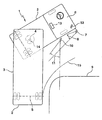
- a vehicle 1 which comprises a trained as a semi-trailer towing vehicle part 2 and designed as a semi-trailer trailed vehicle part 3 .
- the towed vehicle part 3 is pivotally connected to the towing vehicle part 2 at the pivot point 4 .
- the vehicle part 3 has a towed axle 5 .
- a rearview mirror 7 is provided, which has the viewing angle 8 .
- the route and thus the surrounding area of the axis 5 as well as objects or obstacles on the way of the wheels of the axle 5 on the inside of the curve are outside the viewing angle 8.
- the curb 9 can not be seen by the driver on the rearview mirror 7.
- a pivotable image capture device 10 which is designed as a camera and has an angle of view 11 .
- the images acquired by the image capture device 10 are displayed to the driver in the driver's cab 6 via a display device 12 in the form of a monitor. So that the image capture device 10 always detects the travel path of the towed axis 5 and thus obstacles lying on the way of the axis 5 can always be detected, the image capture device 10 is tracked depending on the pivoting of the towing vehicle part 2 with respect to the towed vehicle part 3.
- the degree of tracking is determined in the embodiment by a control device 13 which drives a Schwenkaktuator the image capture device 10.
- the control device 13 determines from the rotational angle determined by a rotation angle sensor 14 at the pivot point 4 the drag curve 15 and / or the position of the axis 5. From the drag curve 15 or the position of the axis 5 results in the degree of tracking of the image capture device. The control device 13 therefore outputs a corresponding control signal to the actuator of the image capture device 10. It can be seen from the figure that the drag curve 15 and thus the travel path substantially corresponding to the towing curve 15 are in the viewing angle 11 of the image capture device 10. The image capture device 10 thus detects the axle 5, or its wheels on the right side of the vehicle, the towed vehicle part 3 and the surrounding area, which lies on the right side of the vehicle part 3.
Applications Claiming Priority (2)
| Application Number | Priority Date | Filing Date | Title |
|---|---|---|---|
| DE2003151655 DE10351655A1 (de) | 2003-11-05 | 2003-11-05 | Verfahren zur Anzeige des Fahrwegs nachgeschleppter Achsen |
| DE10351655 | 2003-11-05 |
Publications (1)
| Publication Number | Publication Date |
|---|---|
| EP1529689A1 true EP1529689A1 (fr) | 2005-05-11 |
Family
ID=34428568
Family Applications (1)
| Application Number | Title | Priority Date | Filing Date |
|---|---|---|---|
| EP04024700A Withdrawn EP1529689A1 (fr) | 2003-11-05 | 2004-10-16 | Procédé d'affichage du trajectoire d'un essieux tracté de véhicule |
Country Status (2)
| Country | Link |
|---|---|
| EP (1) | EP1529689A1 (fr) |
| DE (1) | DE10351655A1 (fr) |
Cited By (4)
| Publication number | Priority date | Publication date | Assignee | Title |
|---|---|---|---|---|
| WO2010149184A1 (fr) * | 2009-06-24 | 2010-12-29 | Hahn Carl H | Dispositif de rétrovision de véhicule sans rétroviseur latéral |
| US9156496B2 (en) | 2007-03-21 | 2015-10-13 | Ford Global Technologies, Llc | Vehicle maneuvering aids |
| EP3168083A1 (fr) * | 2015-11-13 | 2017-05-17 | MEKRA LANG GmbH & Co. KG | Système et procédé de capture d'une partie arrière d'un véhicule |
| EP3321130A1 (fr) * | 2016-09-07 | 2018-05-16 | Continental Automotive GmbH | Procédé de mise à jour d'une section d'image |
Families Citing this family (5)
| Publication number | Priority date | Publication date | Assignee | Title |
|---|---|---|---|---|
| DE102004037959B4 (de) * | 2004-08-05 | 2010-02-18 | Daimler Ag | System zur automatischen Außenspiegelverstellung |
| DE102006026898A1 (de) * | 2006-06-09 | 2007-12-20 | Hans Dominik | Vorrichtung zur Überwachung des rückwärtigen und seitlichen Raums eines Fahrzeugs |
| DE102016216962B3 (de) * | 2016-09-07 | 2017-12-28 | Continental Automotive Gmbh | Verfahren und Steuerungseinheit zur Nachführung eines Bildausschnitts |
| DE102016015363A1 (de) | 2016-12-17 | 2018-06-21 | Wabco Gmbh | Verfahren zum Überwachen einer Fahrzeugumgebung eines Fahrzeug-Gespanns, sowie Überwachungssystem |
| DE102018217639A1 (de) * | 2018-10-15 | 2020-04-16 | Continental Automotive Gmbh | Verfahren zum Überwachen einer Umgebung eines Gespanns aus einem Zugfahrzeug und einem von dem Zugfahrzeug gezogenen Anhänger sowie Steuervorrichtung für das Zugfahrzeug und Zugfahrzeug mit der Steuervorrichtung |
Citations (8)
| Publication number | Priority date | Publication date | Assignee | Title |
|---|---|---|---|---|
| DE29818214U1 (de) | 1998-10-12 | 2000-02-17 | Tuchscherer Norbert | Seitensichtanlage für Fahrzeuge, insbesondere Lastkraftwagen |
| JP2000118303A (ja) * | 1998-10-09 | 2000-04-25 | Hino Motors Ltd | パワー・ミラーの制御装置 |
| DE19936578A1 (de) * | 1999-08-03 | 2001-03-15 | Artur Berchtold | Rückspiegel mit automatischer Einstellung für Kraftfahrzeuge mit Anhänger |
| GB2356612A (en) * | 1999-11-23 | 2001-05-30 | Ivan Goodchild | Articulated vehicle with rear view video camera |
| EP1114750A2 (fr) * | 2000-01-05 | 2001-07-11 | Robert Bosch Gmbh | Dispositif de positionnement d'un rétroviseur de véhicule |
| JP2001260754A (ja) * | 2000-01-12 | 2001-09-26 | Isuzu Motors Ltd | バックミラー装置 |
| JP2002133597A (ja) * | 2000-10-23 | 2002-05-10 | Isuzu Motors Ltd | バックミラー装置 |
| JP2002181518A (ja) * | 2000-10-02 | 2002-06-26 | Isuzu Motors Ltd | トレーラ連結角検出装置 |
-
2003
- 2003-11-05 DE DE2003151655 patent/DE10351655A1/de not_active Withdrawn
-
2004
- 2004-10-16 EP EP04024700A patent/EP1529689A1/fr not_active Withdrawn
Patent Citations (8)
| Publication number | Priority date | Publication date | Assignee | Title |
|---|---|---|---|---|
| JP2000118303A (ja) * | 1998-10-09 | 2000-04-25 | Hino Motors Ltd | パワー・ミラーの制御装置 |
| DE29818214U1 (de) | 1998-10-12 | 2000-02-17 | Tuchscherer Norbert | Seitensichtanlage für Fahrzeuge, insbesondere Lastkraftwagen |
| DE19936578A1 (de) * | 1999-08-03 | 2001-03-15 | Artur Berchtold | Rückspiegel mit automatischer Einstellung für Kraftfahrzeuge mit Anhänger |
| GB2356612A (en) * | 1999-11-23 | 2001-05-30 | Ivan Goodchild | Articulated vehicle with rear view video camera |
| EP1114750A2 (fr) * | 2000-01-05 | 2001-07-11 | Robert Bosch Gmbh | Dispositif de positionnement d'un rétroviseur de véhicule |
| JP2001260754A (ja) * | 2000-01-12 | 2001-09-26 | Isuzu Motors Ltd | バックミラー装置 |
| JP2002181518A (ja) * | 2000-10-02 | 2002-06-26 | Isuzu Motors Ltd | トレーラ連結角検出装置 |
| JP2002133597A (ja) * | 2000-10-23 | 2002-05-10 | Isuzu Motors Ltd | バックミラー装置 |
Non-Patent Citations (5)
| Title |
|---|
| July 15-17 2003 SAE Automotive Alternate Refrigeration Systems, "R-152a Mobile A/C with Directed Relief Safety System", Mahmoud Ghodbane, Ph.D.; James A. Baker, William R. Hill and Stephen O. Andersen, Ph.D. |
| PATENT ABSTRACTS OF JAPAN vol. 2000, no. 07 29 September 2000 (2000-09-29) * |
| PATENT ABSTRACTS OF JAPAN vol. 2000, no. 26 1 July 2002 (2002-07-01) * |
| PATENT ABSTRACTS OF JAPAN vol. 2002, no. 09 4 September 2002 (2002-09-04) * |
| PATENT ABSTRACTS OF JAPAN vol. 2002, no. 10 10 October 2002 (2002-10-10) * |
Cited By (9)
| Publication number | Priority date | Publication date | Assignee | Title |
|---|---|---|---|---|
| US9156496B2 (en) | 2007-03-21 | 2015-10-13 | Ford Global Technologies, Llc | Vehicle maneuvering aids |
| US9566911B2 (en) | 2007-03-21 | 2017-02-14 | Ford Global Technologies, Llc | Vehicle trailer angle detection system and method |
| US9971943B2 (en) | 2007-03-21 | 2018-05-15 | Ford Global Technologies, Llc | Vehicle trailer angle detection system and method |
| WO2010149184A1 (fr) * | 2009-06-24 | 2010-12-29 | Hahn Carl H | Dispositif de rétrovision de véhicule sans rétroviseur latéral |
| EP3168083A1 (fr) * | 2015-11-13 | 2017-05-17 | MEKRA LANG GmbH & Co. KG | Système et procédé de capture d'une partie arrière d'un véhicule |
| CN106965751A (zh) * | 2015-11-13 | 2017-07-21 | 梅克朗有限两合公司 | 一种捕获车辆后部视野的方法及系统 |
| RU2671919C2 (ru) * | 2015-11-13 | 2018-11-07 | Мекра Ланг Гмбх Унд Ко. Кг | Система и способ видеозахвата задней части транспортного средства |
| US10140525B2 (en) | 2015-11-13 | 2018-11-27 | Mekra Lang Gmbh & Co. Kg | System and method for capturing a rear part of a vehicle |
| EP3321130A1 (fr) * | 2016-09-07 | 2018-05-16 | Continental Automotive GmbH | Procédé de mise à jour d'une section d'image |
Also Published As
| Publication number | Publication date |
|---|---|
| DE10351655A1 (de) | 2005-06-02 |
Similar Documents
| Publication | Publication Date | Title |
|---|---|---|
| EP3219533B1 (fr) | Système de vision pour un véhicule, notamment pour un véhicule utilitaire | |
| EP3501897B1 (fr) | Système de visualisation permettant d'apprehender l'environnement d'un véhicule | |
| EP3024700B1 (fr) | Procédé et dispositif permettant de reproduire une zone latérale et/ou arrière environnant un véhicule | |
| DE112012000466B4 (de) | System und Verfahren zum Manövrieren eines Fahrzeug-Anhänger-Gespanns bei Rückwärtsfahrt | |
| EP2603413B1 (fr) | Procédé d'assistance à une manoeuvre de stationnement d'un véhicule à moteur, système d'aide à la conduite, et véhicule à moteur | |
| DE102016210824A1 (de) | Anhängungshilfe mit Schwenk-/Zoomansicht sowie virtueller Draufsicht | |
| DE102016209927B4 (de) | Überwachungsvorrichtung für das Umfeld eines Fahrzeugs | |
| EP2987663B1 (fr) | Système d'assistance au conducteur pour un attelage de véhicule utilitaire et procédé d'exécution d'un processus d'attelage | |
| DE102015014799A1 (de) | System und Verfahren zur Erfassung eines Heckbereiches eines Fahrzeugs | |
| DE102016120349A1 (de) | Anhängerrückfahrassistenzsystem mit zielmanagement | |
| EP3401167A1 (fr) | Système de remplacement de rétroviseur en tant que système de surveillance par cémera d'un véhicule automobile, en particulier d'un véhicule utilitaire | |
| DE102016100326A1 (de) | Zielüberwachungssystem mit einer Linsenreinigungsvorrichtung | |
| WO2002009433A1 (fr) | Dispositif et procede pour surveiller l'environnement d'un objet | |
| DE102013015847B3 (de) | Sichtsystem | |
| EP3351450A1 (fr) | Procédé et système d'assistance à la conduite destinés à détecter des états dynamiques d'un véhicule utilitaire | |
| DE102018201027A1 (de) | Kamera-Monitor-System sowie Verfahren und Vorrichtung zum Betreiben eines Kamera-Monitor-Systems für ein Kraftfahrzeug | |
| DE102015218033B4 (de) | Verfahren zur Verbesserung der rückwärtigen Sicht in einem Kraftfahrzeug | |
| EP1529689A1 (fr) | Procédé d'affichage du trajectoire d'un essieux tracté de véhicule | |
| DE102013214369B4 (de) | Verfahren und Vorrichtung zur Wiedergabe eines Umgebungsbereichs eines Fahrzeugs | |
| DE112019001414T5 (de) | Steuergerät für ein fahrzeug | |
| DE102011080720A1 (de) | Visualisierung einer Rampenabfahrt | |
| DE102017223098A1 (de) | Verfahren und Vorrichtung zur Ermittlung eines Relativwinkels zwischen zwei Fahrzeugen | |
| DE102012005277B3 (de) | Heckbereichssichtsystem | |
| DE102014006150B4 (de) | Verfahren zur Darstellung unterschiedlicher indirekter Sichtfelder eines Fahrzeugumfeldes und Nutzfahrzeug | |
| DE102014110642A1 (de) | Adaptiver elektronischer Rückspiegel für ein Kraftfahrzeug |
Legal Events
| Date | Code | Title | Description |
|---|---|---|---|
| PUAI | Public reference made under article 153(3) epc to a published international application that has entered the european phase |
Free format text: ORIGINAL CODE: 0009012 |
|
| 17P | Request for examination filed |
Effective date: 20050223 |
|
| AK | Designated contracting states |
Kind code of ref document: A1 Designated state(s): AT BE BG CH CY CZ DE DK EE ES FI FR GB GR HU IE IT LI LU MC NL PL PT RO SE SI SK TR |
|
| AX | Request for extension of the european patent |
Extension state: AL HR LT LV MK |
|
| AKX | Designation fees paid |
Designated state(s): DE FR GB IT SE |
|
| STAA | Information on the status of an ep patent application or granted ep patent |
Free format text: STATUS: THE APPLICATION HAS BEEN WITHDRAWN |
|
| 18W | Application withdrawn |
Effective date: 20061016 |