EP1529665A1 - Tire noise reducing system - Google Patents
Tire noise reducing system Download PDFInfo
- Publication number
- EP1529665A1 EP1529665A1 EP04019203A EP04019203A EP1529665A1 EP 1529665 A1 EP1529665 A1 EP 1529665A1 EP 04019203 A EP04019203 A EP 04019203A EP 04019203 A EP04019203 A EP 04019203A EP 1529665 A1 EP1529665 A1 EP 1529665A1
- Authority
- EP
- European Patent Office
- Prior art keywords
- tire
- noise
- noise damper
- damper
- tapered portion
- Prior art date
- Legal status (The legal status is an assumption and is not a legal conclusion. Google has not performed a legal analysis and makes no representation as to the accuracy of the status listed.)
- Granted
Links
- 230000001603 reducing effect Effects 0.000 title claims abstract description 25
- 239000011148 porous material Substances 0.000 claims abstract description 30
- 230000005484 gravity Effects 0.000 claims abstract description 9
- 230000001154 acute effect Effects 0.000 claims description 3
- 239000011324 bead Substances 0.000 claims description 3
- 239000000853 adhesive Substances 0.000 description 7
- 230000001070 adhesive effect Effects 0.000 description 7
- 229920001971 elastomer Polymers 0.000 description 6
- 238000012360 testing method Methods 0.000 description 6
- 238000007599 discharging Methods 0.000 description 5
- 238000000034 method Methods 0.000 description 5
- 239000005060 rubber Substances 0.000 description 5
- 238000005336 cracking Methods 0.000 description 3
- 239000000835 fiber Substances 0.000 description 3
- 229920002635 polyurethane Polymers 0.000 description 3
- 239000004814 polyurethane Substances 0.000 description 3
- 229920003051 synthetic elastomer Polymers 0.000 description 3
- 239000005061 synthetic rubber Substances 0.000 description 3
- 238000010998 test method Methods 0.000 description 3
- RTZKZFJDLAIYFH-UHFFFAOYSA-N Diethyl ether Chemical compound CCOCC RTZKZFJDLAIYFH-UHFFFAOYSA-N 0.000 description 2
- 239000012790 adhesive layer Substances 0.000 description 2
- 230000000052 comparative effect Effects 0.000 description 2
- 238000010586 diagram Methods 0.000 description 2
- 239000000463 material Substances 0.000 description 2
- 239000011496 polyurethane foam Substances 0.000 description 2
- XLYOFNOQVPJJNP-UHFFFAOYSA-N water Substances O XLYOFNOQVPJJNP-UHFFFAOYSA-N 0.000 description 2
- 229920005830 Polyurethane Foam Polymers 0.000 description 1
- 238000010521 absorption reaction Methods 0.000 description 1
- 230000001133 acceleration Effects 0.000 description 1
- 230000015556 catabolic process Effects 0.000 description 1
- 238000006731 degradation reaction Methods 0.000 description 1
- 239000000806 elastomer Substances 0.000 description 1
- 125000005843 halogen group Chemical group 0.000 description 1
- 230000003301 hydrolyzing effect Effects 0.000 description 1
- 238000002955 isolation Methods 0.000 description 1
- 239000004816 latex Substances 0.000 description 1
- 229920000126 latex Polymers 0.000 description 1
- 230000007774 longterm Effects 0.000 description 1
- 239000000203 mixture Substances 0.000 description 1
- 230000000704 physical effect Effects 0.000 description 1
- 239000004033 plastic Substances 0.000 description 1
- 229920003023 plastic Polymers 0.000 description 1
- 238000000926 separation method Methods 0.000 description 1
- 239000007787 solid Substances 0.000 description 1
- 239000012209 synthetic fiber Substances 0.000 description 1
- 229920002994 synthetic fiber Polymers 0.000 description 1
- 238000009864 tensile test Methods 0.000 description 1
- 239000002341 toxic gas Substances 0.000 description 1
Images


Classifications
-
- B—PERFORMING OPERATIONS; TRANSPORTING
- B60—VEHICLES IN GENERAL
- B60C—VEHICLE TYRES; TYRE INFLATION; TYRE CHANGING; CONNECTING VALVES TO INFLATABLE ELASTIC BODIES IN GENERAL; DEVICES OR ARRANGEMENTS RELATED TO TYRES
- B60C19/00—Tyre parts or constructions not otherwise provided for
- B60C19/002—Noise damping elements provided in the tyre structure or attached thereto, e.g. in the tyre interior
-
- Y—GENERAL TAGGING OF NEW TECHNOLOGICAL DEVELOPMENTS; GENERAL TAGGING OF CROSS-SECTIONAL TECHNOLOGIES SPANNING OVER SEVERAL SECTIONS OF THE IPC; TECHNICAL SUBJECTS COVERED BY FORMER USPC CROSS-REFERENCE ART COLLECTIONS [XRACs] AND DIGESTS
- Y10—TECHNICAL SUBJECTS COVERED BY FORMER USPC
- Y10T—TECHNICAL SUBJECTS COVERED BY FORMER US CLASSIFICATION
- Y10T152/00—Resilient tires and wheels
- Y10T152/10—Tires, resilient
- Y10T152/10036—Cushion and pneumatic combined
- Y10T152/10054—Enclosed cushion
-
- Y—GENERAL TAGGING OF NEW TECHNOLOGICAL DEVELOPMENTS; GENERAL TAGGING OF CROSS-SECTIONAL TECHNOLOGIES SPANNING OVER SEVERAL SECTIONS OF THE IPC; TECHNICAL SUBJECTS COVERED BY FORMER USPC CROSS-REFERENCE ART COLLECTIONS [XRACs] AND DIGESTS
- Y10—TECHNICAL SUBJECTS COVERED BY FORMER USPC
- Y10T—TECHNICAL SUBJECTS COVERED BY FORMER US CLASSIFICATION
- Y10T152/00—Resilient tires and wheels
- Y10T152/10—Tires, resilient
- Y10T152/10495—Pneumatic tire or inner tube
Definitions
- the present invention relates to a tire noise reducing system capable of reducing a road noise caused during driving of a vehicle, and more particularly, to a system having a noise damper disposed in a cavity.
- a road noise is known as one of tire noises.
- the road noise is a sound around from 50 to 400 Hz generated from a tire running on a road surface.
- a cause of the road noise is resonance vibrations of air generated in the tire cavity.
- a tire noise reducing system comprising a tire (b), a rim (c) on which the tire is mounted, and a noise damper (a) disposed in a cavity surrounded by the tire (b) and the rim (c) as shown in Fig. 8(A).
- the noise damper (a) is made of porous material.
- the noise damper (a) absorbs vibrational energy generated in the tire cavity, suppresses the resonance and reduces the road noise.
- the noise damper (a) is fixed to the cavity.
- the noise damper (a) collides against the tire (b) or an inner surface of the rim (c) and is destroyed due to a centrifugal force and lateral force when a vehicle runs, and thus it can not suppress the resonance noise. That is, in order to maintain the noise reducing effect for a long term, durability of the noise damper is desired. Even if the noise damper is fixed to the tire cavity, however, the noise damper is damaged in some cases.
- the present invention provides a tire noise reducing system comprising:
- the noise damper extends in a circumferential direction of the tire, and at least one of ends thereof in the circumferential direction of the tire is provided with a tapered portion.
- a tire noise reducing system 1 of the embodiment comprises a pneumatic tire 2, a wheel rim 3 on which the pneumatic tire is mounted, and a noise damper 5.
- the noise damper 5 is disposed in a cavity 4 surrounded by an inner surface 4S2 of the rim 3 and an inner surface 4S1 of the pneumatic tire 2 mounted on the wheel rim 3.
- the wheel rim 3 comprises a rim 3a on which a tire 2 is mounted, and a disk 3b fixed to the rim 3a.
- the wheel rim 3 of this embodiment is a normal rim defined by standard of JATMA or the like.
- the pneumatic tire 2 comprises a tread portion 2t, a pair of bead portions 2a, and a pair of sidewall portions 2s extending therebetween.
- the pneumatic tire 2 is a radial tire for a passenger car.
- An air-non-permeable inner liner rubber is disposed on the inner surface 4S1 of the tire. With this, the cavity 4 becomes an annular continuous hermetical space.
- the noise damper 5 is made of porous material and extends long in the circumferential direction of the tire.
- the porous material means not only a foamed elastomer or plastic of an open-cell or closed-cell type but also shaped intertangled fiber such as synthetic fiber, plant fiber and animal fiber.
- open-cell type poly-urethane foam is used.
- the porous material has high vibration isolation ability and sound absorption ability, and efficiently absorbs vibrational energy in the cavity 4. As a result, the resonance is suppressed, and road noise becomes small.
- the porous material can easily be shrunk, bent and deformed. Therefore, the porous material does not hinder the mounting operation of the pneumatic tire 2 to the wheel rim 3. Since the porous material has a small specific gravity as compared with a solid rubber, the porous material does not deteriorate the weight balance of the tire.
- the volume V2 of the noise damper 5 should be at least 0.4% the volume V1 of the cavity 4.
- the volume V2 is set in a range of not less than 1%, more preferably not less than 2%, still preferably not less than 4%, but not more than 20% the volume V1.
- volume V2 of the noise damper means the apparent entire volume of the noise damper including inside bubbles.
- the above-mentioned normal inflated condition is such that the tire 2 is mounted on the wheel rim 3 and inflated to a standard pressure but loaded with no tire load.
- the standard pressure is the "maximum air pressure" in JATMA, the “Inflation Pressure” in ETRTO, the maximum pressure given in the "Tire Load Limits at Various Cold Inflation Pressures” table in T&RA of the like. In case of passenger car tires, however, 200 kPa is used as the standard pressure.
- the noise damper 5 is fixed to one or both of the inner surface 4S1 of the tire and the inner surface 4S2 of the wheel rim.
- the bottom surface 5a of the noise damper 5 is fixed to the inner surface 4S1.
- the noise damper 5 is fixed to a tread region J of the inner surface 4S1 of the tire.
- the "tread region J" is a region on the inner side of a belt 7. A centrifugal force when the vehicle runs at high speed acts outward in the radial direction of the tire.
- the tire 2 and the noise damper 5 fixed to the tread region J are strongly pushed against each other by the centrifugal force, thereby preventing the fixing surface from being peeled off.
- a width center line of the noise damper 5 and a tire equator C substantially coincide with each other.
- the shape of the noise damper 5 is symmetrical centered on the tire equator C.
- the cross section shape of the noise damper 5 is asymmetrical, its lateral rigidities are different on the left and right sides, and the noise damper 5 is prone to incline toward a side having a smaller rigidity.
- the cross section shape of the noise damper 5 is not especially limited, and rectangular shape, trapezoidal shape, triangular shape, nose shape, semi-circular shape and the like are suitable.
- a rectangular cross section shape is preferable for the noise damper 5 if the productivity and road noise reducing effect are taken into account.
- a ratio (T1/W1) of the height T1 and the width W1 is not less than 0.4, preferably not less than 0.8, and more preferably not less than 1.0.
- the ratio (T1/W1) is preferably not more than 2.0, preferably not more than 1.8 and more preferably not more than 1.5.
- the noise damper 5 may be fixed to the tire cavity 4 in various methods.
- An adhesive or a double-sided tape is used for fixing the noise damper 5.
- the adhesive is a synthetic rubber-based adhesive such as "solution type adhesive in which synthetic rubber is dissolved in organic solution” and "latex type adhesive in which synthetic rubber is dispersed in water.”
- the double-sided tape may be a sheet base material such as web provided at its both surfaces with adhesive layers, or may be a tape having adhesive layers only without having the sheet base material.
- the inside temperature of the tire when the vehicle runs at high speed increases to about 120°C. Therefore, it is preferable that the double-sided tape has high peel strength at room temperature and high temperature. More specifically, it is preferable that the peel strength at 25°C is 0.147 N/mm (0.015 kgf/mm) or higher, and the peel strength at 125°C is 0.0588 N/mm (0.006 kgf/mm) or higher.
- the peel strength is obtained in the following manner.
- a rubber sheet 20 made of the same rubber as that of the inner surface 4S1 of the tire and a porous sheet 22 having the same composition as that of the noise damper 5 are adhered to each other through a double-sided tape 21 to be tested.
- a cross section of the porous sheet 22 is rectangular having width of 20mm, thickness of 10 mm and length of 120mm.
- One end of both the porous sheet 22 and the rubber sheet 20 in the longitudinal direction are provided with a non-adhesion portion 22a so that they do not adhere to each other.
- the length of the non-adhesion portion 22a is 20mm.
- the non-adhesion portions 22a are pulled in opposite directions using a tensile testing machine, and a pull strength (N) when they are peeled is measured.
- the peel strength can be obtained by dividing the pull strength by the width 20 mm of the porous sheet 22.
- the adhesion surface of the tire 2 smooth.
- a surface of a bladder used when the tire is cured and formed is provided with a plurality of discharging grooves for discharging air between the bladder and the tire.
- traces of the discharging grooves as shown in Fig. 5 remains in the inner side surface 4S1 of the tire after it is cured and formed, and the inner surface 4S1 is formed with a plurality of projections 23.
- projections 23 deteriorate the adhesion strength.
- the pneumatic tire 2 has no projections 23 at least in an adhesive region Y of the inner surface 4S1.
- Such a pneumatic tire 2 can be formed using bladder having no discharging grooves in at least the adhesive region Y or can be prepared by removing the projections 23 after cure.
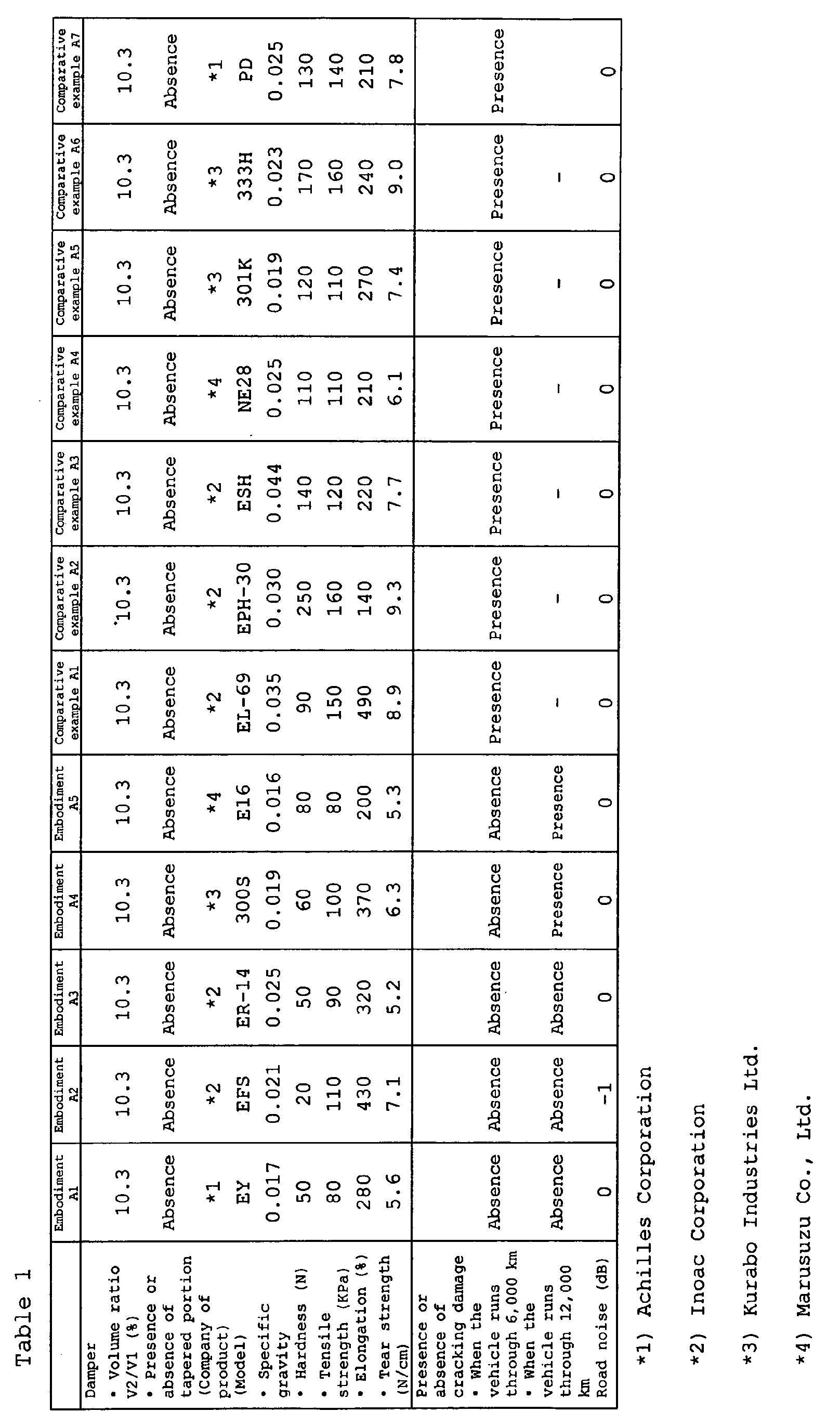
- the noise damper 5 is made of special porous material having a hardness of from 10 to 80N, a tensile strength of not less than 70kPa, and a specific gravity of from 0.014 to 0.026, thereby preventing the damages (g).
- the noise damper 5 is flexibly deformed, and stress intensively existing on the adhesion surface (f) is dispersed in a wide range by elongation of the noise damper 5. More preferably, the hardness of the porous material is in a range of from 20 to 50N. If the hardness of the porous material is less than 10N, the road noise can not be reduced sufficiently, and if the hardness of the porous material is more than 80N, above damage is frequently generated in the porous material.
- a porous material having the tensile strength of not less than 70kPa is used for the noise damper 5, the endurance against the stress can be enhanced.
- a preferable tensile strength of the porous material is not less than 80 kPa, preferably in not more than 160kPa and more preferably not more than 120kPa.
- the mass is reduced, and external force toward the noise damper generated by the acceleration can be reduced. This also reduces the stress itself.
- the damage (g) of the noise damper is suppressed by the synergism, and the durability of the noise damper 5 is largely enhanced. If the specific gravity is excessively small, the road noise can not be reduced sufficiently.
- the elongation when the porous material is ruptured; and tear strength; are determined.
- the elongation is preferably in a range of from 200 to 600%.
- the tear strength is preferably in a range of from 5 to 10N/cm.
- the "hardness of the porous material” is determined in accordance with "soft polyurethane foam test method” defined by in paragraph 6. 3 of JIS K6400.
- the "tensile strength of the porous material” and the “elongation when the porous material is ruptured” are values measured for dumbbell test piece of No. 1 in accordance with a measuring method of "tensile strength and elongation” defined by in paragraph 10 of JIS K6400.
- the specific gravity of the porous material is a value obtained by converting an apparent density measured in accordance with a measuring method of "apparent density” defined by in paragraph 5 of JIS K6400.
- the "tear strength of the porous material” is a value measured for the test piece of No.1 in accordance with a measuring method of "tear strength” defined by in paragraph 11 of JIS K6400.
- ether polyurethane sponge which is strong for hydrolytic degradation is preferable as the porous material. It is preferable that the porous material has repellency and mildewproof. In order to prevent toxic gas from being generated when the tire is incinerated, it is preferable that the porous material does not contain halogen atom.
- Fig. 6 is a side view of the noise damper 5 developed straightly.
- a rod having opposite ends e, e is curved in a form of an arc and the rod is fixed to the cavity 4. Both the ends e, e are provided with the tapered portions 5A.
- the height T1 of the tapered portion 5A in the radial direction of the tire is gradually reduced toward its end.
- the tapered portion 5A includes a bottom surface 5a fixed to the tire 2 (or the wheel rim 3), and an inclined surface 5c intersecting with the bottom surface 5a at an acute angle.
- the tapered portion 5A enables a mass reduced of the end of the noise damper 5. Therefore, the stress acting on the adhesion surface (f) of the end (e) is made small so that the cracking damage (g) is more reliably prevented.
- the angle ⁇ formed between the bottom surface 5a and the inclined surface 5c of the tapered portion 5A is in a range of from 15 to 70°.
- the tapered portion 5A defines a phantom prism portions ya and yb surrounded by an elongation surface E1 of an upper surface 5b of the noise damper 5, a vertical surface E2 extending from the tip end of the inclined surface 5c perpendicularly to the bottom surface 5a, the inclined surface 5c and a pair of side surfaces 5f. It is preferable that volumes Va and Vb of the phantom prism portions ya and yb and the volume V2 of the noise damper satisfy the following relation: 0.08 ⁇ (Va+Vb)/(V2+Va+Vb) ⁇ 0.10
- the inclined surface 5c is formed of substantially flat surface 15 in view of productivity. As shown in Figs. 7 (A) and (B), however, the inclined surface 5c may be formed of a curved surface 16 having an arc surface or a spherical surface projecting in a convex manner or concave manner. At that time, an angle ⁇ formed between the bottom surface 5a and a straight line X connecting upper and lower ends of the curved surface 16 to each other is in a range of from 15 to 70°.
- the maximum separation distance h from the straight line X of the curved surface 16 is preferably 10 mm or less.
- Figs. 7 (C) and (D) show another embodiment of the present invention.
- the width W1 of the tapered portion 5A of the noise damper 5 in the axial direction of the tire is gradually reduced toward its end.
- the height T1 of the tapered portion 5A in the radial direction of the tire is also gradually reduced.
- the noise damper was adhered to a tread region of the inner surface of the tire using a double-sided tape.
- the tread region does not have discharging groove of the bladders.
- the tire noise reducing system was allowed to run on a drum tester (diameter was 1. 7 m) under the following conditions, and when the tire noise reducing system run through 6,000 km and 12,000 km, presence or absence of cracking damage in the outer end of the noise damper in the circumferential direction was checked.
- the tire noise reducing systems were mounted to all wheels of a Japanese 2,000 cc FF vehicle, the vehicle was allowed to run at 60 km/h on a road noise measuring road, and a noise in the vehicle was measured at an ear position on a driver's seat on the side of a window. A sound pressure level of a peak value of resonance around 240 Hz was measured. A result is indicated as a variation value while taking the embodiment A5 as a reference.
- 0 (zero) means that this is equal to the reference
- + (plus) means that the road noise is increased.
- Polyurethane noise dampers having the same physical properties as those of the embodiment A5 were prototyped according to the specifications shown in Tables 2 and 3, and tire noise reducing systems were prototyped using these noise dampers. The vehicle was allowed to run on a stepped road and durability and road noise of the noise damper were tested. The test method is as follows.
- the tire noise reducing systems were allowed to run on a drum having projections (diameter was 1. 7 m) under the following conditions, and a distance through which the tire noise reducing systems run until the cracking damage was generated. The full distance was 10,000 km.
- the drum was provided on its two locations on its circumference with projections having trapezoidal cross sections of 15 mm height ⁇ 40 mm lower bottom ⁇ 20 mm upper bottom.
- the durability is further enhanced.
- the preferable angle is 15° or greater, and more preferably 30° or greater.
Landscapes
- Engineering & Computer Science (AREA)
- Mechanical Engineering (AREA)
- Tires In General (AREA)
Abstract
Description
- the noise damper has a volume V2 which is from 0.4 to 20% of the volume V1 of the cavity, and
- the noise damper is made of a porous material having a hardness of from 10 to 80 N, a tensile strength of not less than 70 kPa and a specific gravity of from 0.014 to 0.026.


Claims (14)
- A tire noise reducing system comprising:whereina pneumatic tire,a wheel rim on which the pneumatic tire is mounted, anda noise damper disposed in a cavity surrounded by an inner surface of the rim and an inner surface of the tire mounted thereon,
the noise damper has a volume V2 which is from 0.4 to 20% of the volume V1 of the cavity, and
the noise damper is made of a porous material having a hardness of from 10 to 80 N, a tensile strength of not less than 70 kPa and a specific gravity of from 0.014 to 0.026. - The tire noise reducing system according to claim 1,
wherein the noise damper extends in a circumferential direction of the tire. - The tire noise reducing system according to claim 2,
wherein a tapered portion is formed on at least one of ends of the noise damper in the circumferential direction of the tire. - The tire noise reducing system according to claim 3,
wherein the height of the tapered portion is gradually reduced in a radial direction of the tire. - The tire noise reducing system according to claim 4,
wherein the tapered portion includes a bottom surface fixed to the tire or wheel rim, and an inclined surface intersecting with the bottom surface at an acute angle. - The tire noise reducing system according to claim 5,
wherein the angle formed between the bottom surface and the inclined surface is from 15 to 70°. - The tire noise reducing system according to any one of claims 3 to 6, wherein
the width of the tapered portion is gradually reduced in an axial direction of the tire. - A pneumatic tire comprising:whereina tread portion,a pair of bead portions,a pair of sidewall portions extending between the tread portion and the bead portions, anda noise damper fixed to an inner surface of the tread portion,
the noise damper is made of porous material having a hardness of from 10 to 80 N, a tensile strength of not less than 70 kPa and a specific gravity of from 0.014 to 0.026. - The pneumatic tire according to claim 8, wherein
the noise damper extends in a circumferential direction of the tire. - The pneumatic tire according to claim 9, wherein
a tapered portion is formed on at least one of ends of the noise damper in the circumferential direction of the tire. - The pneumatic tire according to claim 10, wherein
the height of the tapered portion is gradually reduced in a radial direction of the tire. - The pneumatic tire according to claim 11, wherein
the tapered portion includes a bottom surface fixed to an inner surface of the tread portion and an inclined surface intersecting with the bottom surface at an acute angle. - The pneumatic tire according to claim 12, wherein
the angle formed between the bottom surface and the inclined surface is from 15 to 70°. - The pneumatic tire according to any one of claims 10 to 13, wherein
the width of the tapered portion is gradually reduced in an axial direction of the tire.
Applications Claiming Priority (2)
| Application Number | Priority Date | Filing Date | Title |
|---|---|---|---|
| JP2003378764 | 2003-11-07 | ||
| JP2003378764A JP3787343B2 (en) | 2003-11-07 | 2003-11-07 | Pneumatic tire and rim assembly |
Publications (2)
| Publication Number | Publication Date |
|---|---|
| EP1529665A1 true EP1529665A1 (en) | 2005-05-11 |
| EP1529665B1 EP1529665B1 (en) | 2006-04-26 |
Family
ID=34431358
Family Applications (1)
| Application Number | Title | Priority Date | Filing Date |
|---|---|---|---|
| EP04019203A Expired - Lifetime EP1529665B1 (en) | 2003-11-07 | 2004-08-12 | Tire noise reducing system |
Country Status (5)
| Country | Link |
|---|---|
| US (1) | US7182114B2 (en) |
| EP (1) | EP1529665B1 (en) |
| JP (1) | JP3787343B2 (en) |
| CN (1) | CN100400313C (en) |
| DE (1) | DE602004000753T2 (en) |
Cited By (15)
| Publication number | Priority date | Publication date | Assignee | Title |
|---|---|---|---|---|
| EP1659004A1 (en) * | 2004-11-19 | 2006-05-24 | Sumitomo Rubber Industries, Ltd. | Assembly of pneumatic tire and rim and a noise damper used therein |
| EP1777081A3 (en) * | 2005-10-24 | 2007-06-13 | Sumtiomo Rubber Industries Ltd | Method for manufacturing low noise pneumatic tire |
| WO2007129637A1 (en) | 2006-05-09 | 2007-11-15 | Sumitomo Rubber Industries, Ltd. | Pneumatic tire set |
| EP1798075A3 (en) * | 2005-12-13 | 2008-05-21 | Sumitomo Rubber Industries Ltd. | Pneumatic tire and noise damper assembly |
| EP2067634A4 (en) * | 2006-09-26 | 2009-12-23 | Yokohama Rubber Co Ltd | Tire noise reduction device and pneumatic tire |
| CN1954996B (en) * | 2005-10-24 | 2010-12-15 | 住友橡胶工业株式会社 | Method for manufacturing low noise pneumatic tire |
| GB2496427A (en) * | 2011-11-11 | 2013-05-15 | Bentley Motors Ltd | Vehicle wheel |
| WO2013182477A1 (en) | 2012-06-08 | 2013-12-12 | Compagnie Generale Des Etablissements Michelin | Tyre, the inner wall of which has a layer of specific polyurethane foam |
| EP2962875A1 (en) | 2014-07-04 | 2016-01-06 | Compagnie Generale Des Etablissements Michelin | System for placement of foam ring onto an interior tire surface |
| EP3517317A4 (en) * | 2016-10-18 | 2020-07-01 | Sumitomo Rubber Industries, Ltd. | PNEUMATIC |
| EP3406462B1 (en) | 2017-01-25 | 2020-09-02 | Sumitomo Rubber Industries, Ltd. | Pneumatic tire |
| EP3970998A1 (en) * | 2020-09-17 | 2022-03-23 | Toyo Tire Corporation | Pneumatic tire and method of manufacturing pneumatic tire |
| EP3842259A4 (en) * | 2018-09-19 | 2022-05-11 | Sumitomo Rubber Industries, Ltd. | PNEUMATIC |
| WO2023021300A1 (en) | 2021-08-19 | 2023-02-23 | Carbon Air Limited | A vehicle wheel |
| EP4434775A1 (en) * | 2023-03-22 | 2024-09-25 | Sumitomo Rubber Industries, Ltd. | Tire assembly |
Families Citing this family (60)
| Publication number | Priority date | Publication date | Assignee | Title |
|---|---|---|---|---|
| EP1577123B1 (en) * | 2004-03-16 | 2007-10-17 | Sumitomo Rubber Industries Ltd. | Pneumatic tire with noise damper |
| JP4485280B2 (en) * | 2004-08-04 | 2010-06-16 | 横浜ゴム株式会社 | Pneumatic tire |
| JP4567423B2 (en) * | 2004-11-19 | 2010-10-20 | 住友ゴム工業株式会社 | Tire silencer |
| JP4330550B2 (en) | 2005-04-28 | 2009-09-16 | 住友ゴム工業株式会社 | Pneumatic tire and rim assembly |
| JP4427007B2 (en) * | 2005-06-01 | 2010-03-03 | 住友ゴム工業株式会社 | Pneumatic tire |
| JP4299813B2 (en) * | 2005-07-20 | 2009-07-22 | 住友ゴム工業株式会社 | Pneumatic tire |
| JP4575874B2 (en) | 2005-11-18 | 2010-11-04 | 横浜ゴム株式会社 | Soft polyurethane foam for tire, noise reduction device and tire |
| EP1795378B1 (en) | 2005-12-08 | 2011-05-25 | Sumitomo Rubber Industries, Ltd. | Pneumatic tire with noise damper |
| JP4728790B2 (en) * | 2005-12-08 | 2011-07-20 | 住友ゴム工業株式会社 | Pneumatic tire and rim assembly |
| JP4520936B2 (en) | 2005-12-12 | 2010-08-11 | 住友ゴム工業株式会社 | Pneumatic tire with noise control |
| US7694707B2 (en) | 2005-12-20 | 2010-04-13 | The Goodyear Tire & Rubber Company | Tire with integral foamed noise damper |
| CN101460318B (en) * | 2006-06-02 | 2011-11-23 | 株式会社普利司通 | Pneumatic tire |
| US8365782B2 (en) | 2006-09-26 | 2013-02-05 | The Yokohama Rubber Co., Ltd. | Tire noise reduction device and pneumatic tire |
| FR2908068B1 (en) * | 2006-11-02 | 2009-01-16 | Michelin Soc Tech | METHOD FOR MOLDING A PNEUMATIC HAVING IMPROVED NOISE PERFORMANCE |
| US20100071820A1 (en) * | 2008-09-24 | 2010-03-25 | Bridgestone Americas Tire Operations, Llc | Tire and noise reducer |
| JP4983876B2 (en) * | 2009-09-11 | 2012-07-25 | 横浜ゴム株式会社 | Tire noise reduction device and pneumatic tire provided with the same |
| JP5868303B2 (en) * | 2012-10-16 | 2016-02-24 | 横浜ゴム株式会社 | Pneumatic tire |
| US9302537B2 (en) | 2013-08-16 | 2016-04-05 | GM Global Technology Operations LLC | Noise suppression device for a wheel assembly |
| US9090128B2 (en) | 2013-08-16 | 2015-07-28 | GM Global Technology Operations LLC | Wheel assembly for a vehicle and a method of manufacturing the wheel assembly |
| WO2015076381A1 (en) * | 2013-11-21 | 2015-05-28 | 横浜ゴム株式会社 | Pneumatic tire |
| CN105722693B (en) * | 2013-11-21 | 2017-12-12 | 横滨橡胶株式会社 | Pneumatic tire |
| DE112014005308T5 (en) * | 2013-11-21 | 2016-08-04 | The Yokohama Rubber Co., Ltd. | tire |
| US11427038B2 (en) | 2013-11-21 | 2022-08-30 | The Yokohama Rubber Co., Ltd. | Pneumatic tire |
| JP6281265B2 (en) * | 2013-12-03 | 2018-02-21 | 横浜ゴム株式会社 | Pneumatic tire |
| US20160303923A1 (en) * | 2013-12-03 | 2016-10-20 | The Yokohama Rubber Co., Ltd. | Method for Manufacturing Pneumatic Tire |
| WO2015083780A1 (en) * | 2013-12-04 | 2015-06-11 | 横浜ゴム株式会社 | Pneumatic tire |
| WO2015111314A1 (en) * | 2014-01-23 | 2015-07-30 | 横浜ゴム株式会社 | Pneumatic tire |
| JP6120887B2 (en) | 2014-04-25 | 2017-04-26 | クムホ タイヤ カンパニー インコーポレイテッドKumho Tire Co.,Inc. | Cavity resonance sound reduction tire |
| KR101507401B1 (en) | 2014-04-25 | 2015-03-31 | 금호타이어 주식회사 | Cavity Noise Reduction Tire |
| US10632790B2 (en) | 2014-09-12 | 2020-04-28 | Bridgestone Corporation | Pneumatic tire |
| JP6467950B2 (en) | 2015-01-29 | 2019-02-13 | 横浜ゴム株式会社 | Pneumatic tire |
| DE102015210039A1 (en) * | 2015-06-01 | 2016-12-01 | Continental Reifen Deutschland Gmbh | Vehicle tires |
| JP2017210226A (en) * | 2016-05-27 | 2017-11-30 | クムホ タイヤ シーオー.,インク. | Resonance noise reduction tire having sound absorbing material |
| WO2017223173A1 (en) | 2016-06-21 | 2017-12-28 | Bridgestone Americas Tire Operations, Llc | Methods for treating inner liner surface, inner liners resulting therefrom and tires containing such inner liners |
| WO2018005810A1 (en) | 2016-06-30 | 2018-01-04 | Bridgestone Americas Tire Operations, Llc | Methods for treating inner liners, inner liners resulting therefrom and tires containing such inner liners |
| CN109562645B (en) * | 2016-08-02 | 2020-12-18 | 横滨橡胶株式会社 | run-flat tires |
| JP6927221B2 (en) | 2016-08-02 | 2021-08-25 | 横浜ゴム株式会社 | Pneumatic tires |
| WO2018112117A2 (en) | 2016-12-15 | 2018-06-21 | Bridgestone Americas Tire Operations, Llc | Methods for producing polymer-containing coatings upon cured inner liners, methods for producing tires containing such inner liners, and tires containing such inner liners |
| WO2018112125A1 (en) | 2016-12-15 | 2018-06-21 | Bridgestone Americas Tire Operations, Llc | Sealant-containing tire and related processes |
| WO2018112179A1 (en) | 2016-12-15 | 2018-06-21 | Bridgestone Americas Tire Operations, Llc | Sealant layer with barrier, tire containing same, and related processes |
| JP7097362B2 (en) * | 2016-12-23 | 2022-07-07 | ピレリ・タイヤ・ソチエタ・ペル・アツィオーニ | Methods and equipment for attaching noise reduction elements to tires for vehicle wheels |
| JP6954122B2 (en) * | 2017-02-08 | 2021-10-27 | 横浜ゴム株式会社 | Pneumatic tires and their manufacturing methods |
| WO2018146886A1 (en) * | 2017-02-08 | 2018-08-16 | 横浜ゴム株式会社 | Pneumatic tire and method for producing same |
| US12409686B2 (en) | 2017-09-07 | 2025-09-09 | The Yokohama Rubber Co., Ltd. | Pneumatic tire and method for manufacturing the same |
| JP6583382B2 (en) * | 2017-10-19 | 2019-10-02 | 横浜ゴム株式会社 | Pneumatic tire |
| JP6583383B2 (en) * | 2017-10-19 | 2019-10-02 | 横浜ゴム株式会社 | Pneumatic tire |
| US11760136B2 (en) | 2018-05-15 | 2023-09-19 | Bridgestone Americas Tire Operations, Llc | Tire with multi-layer insert |
| TWI741200B (en) | 2018-07-20 | 2021-10-01 | 正新橡膠工業股份有限公司 | Tire noise reduction device |
| ES2960806T3 (en) * | 2019-03-08 | 2024-03-06 | Trelleborg Retford Ltd | A noise damper and a method of producing a noise damper |
| JP7238562B2 (en) * | 2019-04-11 | 2023-03-14 | 横浜ゴム株式会社 | pneumatic tire |
| CN110027367A (en) * | 2019-04-16 | 2019-07-19 | 安徽佳通乘用子午线轮胎有限公司 | A kind of noise absorption body and its method of attaching for pneumatic tire |
| CN110039963A (en) * | 2019-04-16 | 2019-07-23 | 安徽佳通乘用子午线轮胎有限公司 | A kind of low noise pneumatic tire |
| KR102023044B1 (en) * | 2019-04-22 | 2019-09-19 | 주식회사 폼웍스 | Laminated tires Sound absorption profile |
| JP7484365B2 (en) | 2020-04-15 | 2024-05-16 | 住友ゴム工業株式会社 | Pneumatic tires |
| JP7753634B2 (en) * | 2020-10-26 | 2025-10-15 | 住友ゴム工業株式会社 | pneumatic tires |
| JP7586761B2 (en) * | 2021-04-28 | 2024-11-19 | 株式会社ブリヂストン | Pneumatic tires |
| JP2023097897A (en) | 2021-12-28 | 2023-07-10 | 住友ゴム工業株式会社 | pneumatic tire |
| JP7797871B2 (en) | 2021-12-28 | 2026-01-14 | 住友ゴム工業株式会社 | pneumatic tires |
| JP2024018103A (en) * | 2022-07-29 | 2024-02-08 | 住友ゴム工業株式会社 | Pneumatic tire |
| LU503431B1 (en) | 2023-02-03 | 2024-08-05 | Apollo Tyres Global R & D Bv | Pneumatic tyre comprising sound absorbing device |
Citations (4)
| Publication number | Priority date | Publication date | Assignee | Title |
|---|---|---|---|---|
| JPH0717222A (en) * | 1993-07-05 | 1995-01-20 | Bridgestone Corp | Core assembly body for pneumatic tire |
| DE19750229A1 (en) * | 1997-11-13 | 1999-06-02 | Continental Ag | Tubeless tire combining self-healing and run-flat capabilities |
| DE19806935A1 (en) * | 1998-02-19 | 1999-09-09 | Continental Ag | Vehicle pneumatic tire with sound absorbing foam layer |
| EP1253025A2 (en) * | 2001-04-16 | 2002-10-30 | Sumitomo Rubber Industries Ltd. | Tire noise reducing system |
Family Cites Families (17)
| Publication number | Priority date | Publication date | Assignee | Title |
|---|---|---|---|---|
| US2702769A (en) * | 1951-08-16 | 1955-02-22 | Edward D Andrews | Method of making sponge rubber articles and product |
| JPS6250203A (en) * | 1985-08-29 | 1987-03-04 | Bridgestone Corp | Low noise tyre wheel |
| JPS62216803A (en) * | 1986-03-17 | 1987-09-24 | Bridgestone Corp | Tyre resonance preventing material |
| JPS6478902A (en) | 1987-06-26 | 1989-03-24 | Bridgestone Corp | Low noise tire wheel |
| CN2248655Y (en) * | 1995-11-14 | 1997-03-05 | 祝能武 | External tyre |
| CN2336989Y (en) * | 1998-04-13 | 1999-09-08 | 陈福祥 | Safety tyre |
| JP2001151919A (en) * | 1999-11-30 | 2001-06-05 | Achilles Corp | Method for manufacturing flame-retardant polyurethane foam |
| JP3990533B2 (en) * | 2000-08-31 | 2007-10-17 | 住友ゴム工業株式会社 | Pneumatic tire and rim assembly |
| JP3953264B2 (en) * | 2000-08-31 | 2007-08-08 | 住友ゴム工業株式会社 | Pneumatic tire and rim assembly |
| JP4367598B2 (en) * | 2000-12-11 | 2009-11-18 | 横浜ゴム株式会社 | Tire / wheel assembly |
| JP3400787B2 (en) * | 2000-12-26 | 2003-04-28 | 住友ゴム工業株式会社 | How to correct tire imbalance |
| JP3612059B2 (en) * | 2002-03-05 | 2005-01-19 | 住友ゴム工業株式会社 | Pneumatic tire and rim assembly |
| JP3621899B2 (en) * | 2001-08-28 | 2005-02-16 | 住友ゴム工業株式会社 | Pneumatic tire and rim assembly |
| JP3622957B2 (en) * | 2001-08-02 | 2005-02-23 | 住友ゴム工業株式会社 | Pneumatic tire and rim assembly |
| JP3995489B2 (en) * | 2002-02-05 | 2007-10-24 | 横浜ゴム株式会社 | Pneumatic tire and tire cavity resonance suppression device |
| WO2003103989A1 (en) * | 2002-06-05 | 2003-12-18 | 住友ゴム工業株式会社 | Assembly of pneumatic tire and rim, sound suppressing body used for the assembly, and pneumatic tire storage method |
| US6726389B1 (en) * | 2003-05-15 | 2004-04-27 | Kuo-Jium Lee | Paint brush assembly having two-stage anti-reverse effect |
-
2003
- 2003-11-07 JP JP2003378764A patent/JP3787343B2/en not_active Expired - Lifetime
-
2004
- 2004-08-12 EP EP04019203A patent/EP1529665B1/en not_active Expired - Lifetime
- 2004-08-12 DE DE602004000753T patent/DE602004000753T2/en not_active Expired - Lifetime
- 2004-08-23 US US10/922,854 patent/US7182114B2/en not_active Expired - Lifetime
- 2004-11-08 CN CNB2004100907405A patent/CN100400313C/en not_active Expired - Lifetime
Patent Citations (4)
| Publication number | Priority date | Publication date | Assignee | Title |
|---|---|---|---|---|
| JPH0717222A (en) * | 1993-07-05 | 1995-01-20 | Bridgestone Corp | Core assembly body for pneumatic tire |
| DE19750229A1 (en) * | 1997-11-13 | 1999-06-02 | Continental Ag | Tubeless tire combining self-healing and run-flat capabilities |
| DE19806935A1 (en) * | 1998-02-19 | 1999-09-09 | Continental Ag | Vehicle pneumatic tire with sound absorbing foam layer |
| EP1253025A2 (en) * | 2001-04-16 | 2002-10-30 | Sumitomo Rubber Industries Ltd. | Tire noise reducing system |
Non-Patent Citations (2)
| Title |
|---|
| PATENT ABSTRACTS OF JAPAN vol. 013, no. 282 (M - 843) 28 June 1989 (1989-06-28) * |
| PATENT ABSTRACTS OF JAPAN vol. 1995, no. 04 31 May 1995 (1995-05-31) * |
Cited By (25)
| Publication number | Priority date | Publication date | Assignee | Title |
|---|---|---|---|---|
| US7455092B2 (en) | 2004-11-19 | 2008-11-25 | Sumitomo Rubber Industries, Ltd. | Assembly of pneumatic tire and rim, and a noise damper used therein |
| EP1659004A1 (en) * | 2004-11-19 | 2006-05-24 | Sumitomo Rubber Industries, Ltd. | Assembly of pneumatic tire and rim and a noise damper used therein |
| US8033309B2 (en) | 2004-11-19 | 2011-10-11 | Sumitomo Rubber Industries, Ltd. | Assembly of pneumatic tire and rim, and a noise damper used therein |
| CN1954996B (en) * | 2005-10-24 | 2010-12-15 | 住友橡胶工业株式会社 | Method for manufacturing low noise pneumatic tire |
| EP1777081A3 (en) * | 2005-10-24 | 2007-06-13 | Sumtiomo Rubber Industries Ltd | Method for manufacturing low noise pneumatic tire |
| US8276631B2 (en) | 2005-10-24 | 2012-10-02 | Sumitomo Rubber Industries, Ltd. | Method for manufacturing low noise pneumatic tire |
| EP1967391A3 (en) * | 2005-10-24 | 2008-09-24 | Sumitomo Rubber Industries, Ltd. | Method for manufacturing low noise pneumatic tire |
| US7669628B2 (en) | 2005-10-24 | 2010-03-02 | Sumitomo Rubber Industries, Ltd. | Method for manufacturing low noise pneumatic tire |
| EP1798075A3 (en) * | 2005-12-13 | 2008-05-21 | Sumitomo Rubber Industries Ltd. | Pneumatic tire and noise damper assembly |
| US7681613B2 (en) | 2005-12-13 | 2010-03-23 | Sumitomo Rubber Industries, Ltd. | Pneumatic tire and noise damper assembly |
| EP2017092A4 (en) * | 2006-05-09 | 2009-11-04 | Sumitomo Rubber Ind | Pneumatic tire set |
| WO2007129637A1 (en) | 2006-05-09 | 2007-11-15 | Sumitomo Rubber Industries, Ltd. | Pneumatic tire set |
| EP2067634A4 (en) * | 2006-09-26 | 2009-12-23 | Yokohama Rubber Co Ltd | Tire noise reduction device and pneumatic tire |
| CN101516643B (en) * | 2006-09-26 | 2013-04-17 | 横滨橡胶株式会社 | Tire noise reduction device and pneumatic tire |
| GB2496427B (en) * | 2011-11-11 | 2018-08-08 | Bentley Motors Ltd | Vehicle wheel |
| GB2496427A (en) * | 2011-11-11 | 2013-05-15 | Bentley Motors Ltd | Vehicle wheel |
| WO2013182477A1 (en) | 2012-06-08 | 2013-12-12 | Compagnie Generale Des Etablissements Michelin | Tyre, the inner wall of which has a layer of specific polyurethane foam |
| US10611196B2 (en) | 2012-06-08 | 2020-04-07 | Compagnie Generale Des Etablissements Michelin | Tire, the inner wall of which has a layer of specific polyurethane foam |
| EP2962875A1 (en) | 2014-07-04 | 2016-01-06 | Compagnie Generale Des Etablissements Michelin | System for placement of foam ring onto an interior tire surface |
| EP3517317A4 (en) * | 2016-10-18 | 2020-07-01 | Sumitomo Rubber Industries, Ltd. | PNEUMATIC |
| EP3406462B1 (en) | 2017-01-25 | 2020-09-02 | Sumitomo Rubber Industries, Ltd. | Pneumatic tire |
| EP3842259A4 (en) * | 2018-09-19 | 2022-05-11 | Sumitomo Rubber Industries, Ltd. | PNEUMATIC |
| EP3970998A1 (en) * | 2020-09-17 | 2022-03-23 | Toyo Tire Corporation | Pneumatic tire and method of manufacturing pneumatic tire |
| WO2023021300A1 (en) | 2021-08-19 | 2023-02-23 | Carbon Air Limited | A vehicle wheel |
| EP4434775A1 (en) * | 2023-03-22 | 2024-09-25 | Sumitomo Rubber Industries, Ltd. | Tire assembly |
Also Published As
| Publication number | Publication date |
|---|---|
| US20050098251A1 (en) | 2005-05-12 |
| JP2005138760A (en) | 2005-06-02 |
| DE602004000753T2 (en) | 2007-04-26 |
| EP1529665B1 (en) | 2006-04-26 |
| CN1613672A (en) | 2005-05-11 |
| CN100400313C (en) | 2008-07-09 |
| JP3787343B2 (en) | 2006-06-21 |
| DE602004000753D1 (en) | 2006-06-01 |
| US7182114B2 (en) | 2007-02-27 |
Similar Documents
| Publication | Publication Date | Title |
|---|---|---|
| EP1529665B1 (en) | Tire noise reducing system | |
| US7975740B2 (en) | Pneumatic tire and rim assembly with noise damper and pneumatic tire with noise damper | |
| US8281834B2 (en) | Assembly of pneumatic tire, noise damper, and rim | |
| JP4787784B2 (en) | Pneumatic tire set | |
| EP1510366B1 (en) | Assembly of pneumatic tire and rim, sound suppressing body used for the assembly, and pneumatic tire storage method | |
| JP6519471B2 (en) | Pneumatic tire | |
| JP3934621B2 (en) | Pneumatic tire and rim assembly | |
| JP4783135B2 (en) | Pneumatic tire with noise control | |
| EP1728650B1 (en) | Pneumatic tire | |
| EP1745947B1 (en) | Pneumatic tire with noise absorbing insert | |
| JP3964878B2 (en) | Pneumatic tire and rim assembly | |
| US20100012244A1 (en) | Tire noise reduction device and pneumatic tire | |
| JP2003063208A (en) | Pneumatic tire and rim assembly | |
| JP2005297836A (en) | Tire wheel assembly and run-flat core | |
| JP4960626B2 (en) | Pneumatic tire with noise control |
Legal Events
| Date | Code | Title | Description |
|---|---|---|---|
| PUAI | Public reference made under article 153(3) epc to a published international application that has entered the european phase |
Free format text: ORIGINAL CODE: 0009012 |
|
| AK | Designated contracting states |
Kind code of ref document: A1 Designated state(s): AT BE BG CH CY CZ DE DK EE ES FI FR GB GR HU IE IT LI LU MC NL PL PT RO SE SI SK TR |
|
| AX | Request for extension of the european patent |
Extension state: AL HR LT LV MK |
|
| GRAP | Despatch of communication of intention to grant a patent |
Free format text: ORIGINAL CODE: EPIDOSNIGR1 |
|
| 17P | Request for examination filed |
Effective date: 20050613 |
|
| GRAS | Grant fee paid |
Free format text: ORIGINAL CODE: EPIDOSNIGR3 |
|
| AKX | Designation fees paid |
Designated state(s): DE FR GB |
|
| GRAA | (expected) grant |
Free format text: ORIGINAL CODE: 0009210 |
|
| AK | Designated contracting states |
Kind code of ref document: B1 Designated state(s): DE FR GB |
|
| REG | Reference to a national code |
Ref country code: GB Ref legal event code: FG4D |
|
| REF | Corresponds to: |
Ref document number: 602004000753 Country of ref document: DE Date of ref document: 20060601 Kind code of ref document: P |
|
| ET | Fr: translation filed | ||
| PLBE | No opposition filed within time limit |
Free format text: ORIGINAL CODE: 0009261 |
|
| STAA | Information on the status of an ep patent application or granted ep patent |
Free format text: STATUS: NO OPPOSITION FILED WITHIN TIME LIMIT |
|
| 26N | No opposition filed |
Effective date: 20070129 |
|
| PGFP | Annual fee paid to national office [announced via postgrant information from national office to epo] |
Ref country code: GB Payment date: 20090812 Year of fee payment: 6 |
|
| GBPC | Gb: european patent ceased through non-payment of renewal fee |
Effective date: 20100812 |
|
| PG25 | Lapsed in a contracting state [announced via postgrant information from national office to epo] |
Ref country code: GB Free format text: LAPSE BECAUSE OF NON-PAYMENT OF DUE FEES Effective date: 20100812 |
|
| REG | Reference to a national code |
Ref country code: FR Ref legal event code: PLFP Year of fee payment: 13 |
|
| REG | Reference to a national code |
Ref country code: FR Ref legal event code: PLFP Year of fee payment: 14 |
|
| REG | Reference to a national code |
Ref country code: FR Ref legal event code: PLFP Year of fee payment: 15 |
|
| P01 | Opt-out of the competence of the unified patent court (upc) registered |
Effective date: 20230510 |
|
| PGFP | Annual fee paid to national office [announced via postgrant information from national office to epo] |
Ref country code: FR Payment date: 20230703 Year of fee payment: 20 Ref country code: DE Payment date: 20230627 Year of fee payment: 20 |
|
| REG | Reference to a national code |
Ref country code: DE Ref legal event code: R071 Ref document number: 602004000753 Country of ref document: DE |