JP6583383B2 - Pneumatic tire - Google Patents
Pneumatic tire Download PDFInfo
- Publication number
- JP6583383B2 JP6583383B2 JP2017202643A JP2017202643A JP6583383B2 JP 6583383 B2 JP6583383 B2 JP 6583383B2 JP 2017202643 A JP2017202643 A JP 2017202643A JP 2017202643 A JP2017202643 A JP 2017202643A JP 6583383 B2 JP6583383 B2 JP 6583383B2
- Authority
- JP
- Japan
- Prior art keywords
- absorbing material
- sound absorbing
- tire
- pneumatic tire
- sound
- Prior art date
- Legal status (The legal status is an assumption and is not a legal conclusion. Google has not performed a legal analysis and makes no representation as to the accuracy of the status listed.)
- Active
Links
- 239000011358 absorbing material Substances 0.000 claims description 146
- 239000012790 adhesive layer Substances 0.000 claims description 19
- 239000011324 bead Substances 0.000 claims description 12
- 239000002390 adhesive tape Substances 0.000 claims description 7
- 238000000034 method Methods 0.000 claims description 4
- 239000010410 layer Substances 0.000 description 13
- 230000000694 effects Effects 0.000 description 12
- 238000012360 testing method Methods 0.000 description 11
- 230000000052 comparative effect Effects 0.000 description 6
- 230000003014 reinforcing effect Effects 0.000 description 6
- 230000000704 physical effect Effects 0.000 description 5
- 238000005096 rolling process Methods 0.000 description 4
- 230000006835 compression Effects 0.000 description 3
- 238000007906 compression Methods 0.000 description 3
- 230000002093 peripheral effect Effects 0.000 description 3
- 239000011148 porous material Substances 0.000 description 3
- 239000000853 adhesive Substances 0.000 description 2
- 230000001070 adhesive effect Effects 0.000 description 2
- 239000000835 fiber Substances 0.000 description 2
- 238000005338 heat storage Methods 0.000 description 2
- 230000004048 modification Effects 0.000 description 2
- 238000012986 modification Methods 0.000 description 2
- 238000000465 moulding Methods 0.000 description 2
- 238000010008 shearing Methods 0.000 description 2
- 239000004677 Nylon Substances 0.000 description 1
- 229910000831 Steel Inorganic materials 0.000 description 1
- 238000010521 absorption reaction Methods 0.000 description 1
- 239000004760 aramid Substances 0.000 description 1
- 229920003235 aromatic polyamide Polymers 0.000 description 1
- 239000000945 filler Substances 0.000 description 1
- 230000017525 heat dissipation Effects 0.000 description 1
- 230000007774 longterm Effects 0.000 description 1
- 238000004519 manufacturing process Methods 0.000 description 1
- 239000000463 material Substances 0.000 description 1
- 229920001778 nylon Polymers 0.000 description 1
- 229920002635 polyurethane Polymers 0.000 description 1
- 239000004814 polyurethane Substances 0.000 description 1
- 230000002940 repellent Effects 0.000 description 1
- 239000005871 repellent Substances 0.000 description 1
- 238000007493 shaping process Methods 0.000 description 1
- 239000010959 steel Substances 0.000 description 1
- 238000010998 test method Methods 0.000 description 1
- 230000009466 transformation Effects 0.000 description 1
- XLYOFNOQVPJJNP-UHFFFAOYSA-N water Substances O XLYOFNOQVPJJNP-UHFFFAOYSA-N 0.000 description 1
- 239000013585 weight reducing agent Substances 0.000 description 1
Images


Classifications
-
- B—PERFORMING OPERATIONS; TRANSPORTING
- B60—VEHICLES IN GENERAL
- B60C—VEHICLE TYRES; TYRE INFLATION; TYRE CHANGING; CONNECTING VALVES TO INFLATABLE ELASTIC BODIES IN GENERAL; DEVICES OR ARRANGEMENTS RELATED TO TYRES
- B60C19/00—Tyre parts or constructions not otherwise provided for
- B60C19/002—Noise damping elements provided in the tyre structure or attached thereto, e.g. in the tyre interior
Landscapes
- Engineering & Computer Science (AREA)
- Mechanical Engineering (AREA)
- Tires In General (AREA)
Description
本発明は、空気入りタイヤに関し、更に詳しくは、高速走行時において吸音材による吸音効果を得ながら、低温時において吸音材の剥離や破断を防止することを可能にした空気入りタイヤに関する。 The present invention relates to a pneumatic tire. More specifically, the present invention relates to a pneumatic tire capable of preventing the sound absorbing material from peeling or breaking at low temperatures while obtaining a sound absorbing effect by the sound absorbing material during high-speed traveling.
タイヤ騒音を発生させる原因の一つにタイヤ空洞部に充填された空気の振動による空洞共鳴音がある。この空洞共鳴音は、車両走行時に路面と接地するタイヤのトレッド部が路面の凹凸によって振動し、この振動がタイヤ空洞部内の空気を振動させることによって生じる。この空洞共鳴音の中でも特定の周波数帯域の音が騒音として知覚されるので、その周波数帯域の音圧レベル(騒音レベル)を低下させることが空洞共鳴音を低減するうえで重要である。 One cause of tire noise is cavity resonance due to vibration of air filled in the tire cavity. This cavity resonance sound is generated when the tread portion of the tire that comes in contact with the road surface when the vehicle travels vibrates due to the unevenness of the road surface, and this vibration vibrates the air in the tire cavity portion. Among these cavity resonance sounds, a sound in a specific frequency band is perceived as noise. Therefore, reducing the sound pressure level (noise level) in the frequency band is important for reducing the cavity resonance sound.
このような空洞共鳴現象による騒音を低減させる方法として、タイヤ内面にスポンジ等の多孔質材料からなる吸音材を弾性固定バンドによりトレッド部の内周面に装着することが提案されている(例えば、特許文献1参照)。しかしながら、吸音材の固定を弾性固定バンドに依存した場合、高速走行時において弾性固定バンドが変形してしまうという問題がある。 As a method of reducing noise due to such a cavity resonance phenomenon, it has been proposed that a sound absorbing material made of a porous material such as a sponge is attached to the inner surface of the tread portion by an elastic fixing band on the tire inner surface (for example, Patent Document 1). However, when fixing the sound absorbing material depends on the elastic fixing band, there is a problem that the elastic fixing band is deformed during high speed traveling.
これに対して、吸音材をタイヤ内面に直接接着して固定する方法が提案されている(例えば、特許文献2参照)。しかしながら、タイヤ内面に固定された吸音材が低伸度の特性を有する場合、低温時において吸音材がタイヤの変形に追従することができず、吸音材の剥離や破断が顕著に発生するという問題がある。また、タイヤ内面に固定された吸音材が高伸度の特性を有する場合、高速走行時において吸音材が圧縮永久歪により変形し、十分な吸音効果を得ることができないという問題がある。 On the other hand, a method of directly adhering and fixing the sound absorbing material to the tire inner surface has been proposed (for example, see Patent Document 2). However, when the sound absorbing material fixed to the tire inner surface has a low elongation characteristic, the sound absorbing material cannot follow the deformation of the tire at a low temperature, and the sound absorbing material peels or breaks significantly. There is. Further, when the sound absorbing material fixed to the tire inner surface has a high elongation characteristic, there is a problem that the sound absorbing material is deformed by compression set during high-speed running, and a sufficient sound absorbing effect cannot be obtained.
本発明の目的は、高速走行時において吸音材による吸音効果を得ながら、低温時において吸音材の剥離や破断を防止することを可能にした空気入りタイヤを提供することにある。 An object of the present invention is to provide a pneumatic tire capable of preventing the sound absorbing material from peeling or breaking at low temperatures while obtaining a sound absorbing effect by the sound absorbing material during high-speed traveling.
上記目的を達成するための空気入りタイヤは、タイヤ周方向に延在して環状をなすトレッド部と、該トレッド部の両側に配置された一対のサイドウォール部と、これらサイドウォール部のタイヤ径方向内側に配置された一対のビード部とを備えた空気入りタイヤにおいて、前記トレッド部の内面にタイヤ周方向に沿って接着層を介して吸音材が固定され、前記吸音材の温度t[℃]が少なくとも−20℃〜80℃の範囲にあるときに前記吸音材の破断伸度y[%]が該吸音材の温度t[℃]に対してy≧t+100かつy≦2t+440の関係を満たし、前記吸音材のセル数が30個/25mm〜80個/25mmであり、前記接着層が両面接着テープからなり、前記接着層の総厚さが10μm〜150μmであることを特徴とするものである。 A pneumatic tire for achieving the above object includes a tread portion that extends in the tire circumferential direction and has an annular shape, a pair of sidewall portions disposed on both sides of the tread portion, and tire diameters of the sidewall portions. In a pneumatic tire including a pair of bead portions arranged on the inner side in the direction, a sound absorbing material is fixed to an inner surface of the tread portion via an adhesive layer along a tire circumferential direction, and the temperature t [° C. of the sound absorbing material is fixed. ] At least in the range of −20 ° C. to 80 ° C., the breaking elongation y [%] of the sound absorbing material satisfies the relationship of y ≧ t + 100 and y ≦ 2t + 440 with respect to the temperature t [° C.] of the sound absorbing material. The number of cells of the sound absorbing material is 30/25 mm to 80/25 mm, the adhesive layer is made of double-sided adhesive tape, and the total thickness of the adhesive layer is 10 μm to 150 μm. Is .
本発明では、タイヤ周方向に延在して環状をなすトレッド部と、トレッド部の両側に配置された一対のサイドウォール部と、これらサイドウォール部のタイヤ径方向内側に配置された一対のビード部とを備えた空気入りタイヤにおいて、トレッド部の内面にタイヤ周方向に沿って接着層を介して吸音材が固定され、吸音材の温度t[℃]が少なくとも−20℃〜80℃の範囲にあるときに吸音材の破断伸度y[%]は吸音材の温度t[℃]に対してy≧t+100かつy≦2t+440の関係を満たすことで、高速走行時において吸音材の吸音効果を十分に確保することができると共に、低温時において吸音材の剥離や破断を防止することができる。
In the present invention, an annular tread portion extending in the tire circumferential direction, a pair of sidewall portions disposed on both sides of the tread portion, and a pair of beads disposed inside the tire radial direction of these sidewall portions In the pneumatic tire provided with the portion, the sound absorbing material is fixed to the inner surface of the tread portion through the adhesive layer along the tire circumferential direction, and the temperature t [° C.] of the sound absorbing material is at least in the range of −20 ° C. to 80 ° C. The breaking elongation y [%] of the sound-absorbing material satisfies the relationship of y ≧ t + 100 and
本発明では、吸音材の硬度x[N/314cm2]と吸音材の破断伸度y[%]とは、130≦y≦500、y≦−21x+2770及びx>80の関係を満たすことが好ましい。これにより、高荷重時又は低温時において吸音材の剥離や破断を効果的に防止することができる。 In the present invention, it is preferable that the hardness x [N / 314 cm 2 ] of the sound absorbing material and the breaking elongation y [%] of the sound absorbing material satisfy the relationship of 130 ≦ y ≦ 500, y ≦ −21x + 2770, and x> 80. . Thereby, peeling and a fracture | rupture of a sound absorption material can be effectively prevented at the time of high load or low temperature.
本発明では、吸音材の密度は10kg/m3〜30kg/m3であり、吸音材のセル数は30個/25mm〜80個/25mmであることが好ましい。これにより、吸音材が低密度となって軽量化を図ることができ、転がり抵抗の低減に繋がる。また、吸音材のセル数を適度に設定することで、気泡を細かくすることができ、吸音材の吸音効果を十分に確保することができる。 In the present invention, the density of the sound absorbing material is 10 kg / m 3 to 30 kg / m 3 , and the number of cells of the sound absorbing material is preferably 30/25 mm to 80/25 mm. Thereby, a sound-absorbing material becomes low density and can achieve weight reduction, and it leads to reduction of rolling resistance. Moreover, by setting the number of cells of the sound absorbing material appropriately, the bubbles can be made finer and the sound absorbing effect of the sound absorbing material can be sufficiently secured.
本発明では、吸音材の体積はタイヤの内腔体積に対して10%〜30%であることが好ましい。これにより、吸音材の吸音効果を十分に確保することでき、静穏性の向上に繋がる。 In the present invention, the volume of the sound absorbing material is preferably 10% to 30% with respect to the lumen volume of the tire. Thereby, the sound-absorbing effect of the sound-absorbing material can be sufficiently ensured, and the quietness is improved.
本発明では、吸音材は長方形の断面形状を有する1枚の帯状体からなり、吸音材を構成する帯状体はタイヤ赤道を跨ぐように配置されていることが好ましい。タイヤ内面に1枚の吸音材が配置された場合において、低温時における吸音材の剥離や破断を効果的に防止することができる。 In the present invention, the sound absorbing material is preferably composed of a single band-shaped body having a rectangular cross-sectional shape, and the band-shaped body constituting the sound absorbing material is preferably disposed so as to straddle the tire equator. When one sound absorbing material is arranged on the tire inner surface, it is possible to effectively prevent the sound absorbing material from peeling or breaking at low temperatures.
本発明では、トレッド部にタイヤ全周に亘って連続的に延在してタイヤ赤道上に配置されたセンター陸部を有する空気入りタイヤであって、吸音材は長方形の断面形状を有する第一の帯状体と第二の帯状体からなり、吸音材を構成する第一の帯状体はセンター陸部のタイヤ幅方向の一方側の端部からタイヤ幅方向の他方側に向かってセンター陸部の幅の40%の位置よりもタイヤ幅方向の一方側に配置され、吸音材を構成する第二の帯状体はセンター陸部のタイヤ幅方向の他方側の端部からタイヤ幅方向の一方側に向かってセンター陸部の幅の40%の位置よりもタイヤ幅方向の他方側に配置され、かつ、吸音材を構成する第一の帯状体と第二の帯状体とはセンター陸部の幅の60%以上離間していることが好ましい。タイヤ内面に複数枚の吸音材を配置する場合には、ショルダー部に対応する領域付近にも吸音材を配置する必要が生じ、そのような部位に配置した吸音材において高速耐久性を十分に確保できないことがある。上述のようにタイヤ内面に複数枚の吸音材を配置することで、高速走行時における蓄熱を効果的に抑制し、高速耐久性を高めることができ、騒音性能と高速耐久性とをバランスよく改善することができる。 In the present invention, a pneumatic tire having a center land portion continuously extending in the tread portion over the entire circumference of the tire and disposed on the tire equator, wherein the sound absorbing material has a rectangular cross-sectional shape. The first belt-shaped body that constitutes the sound absorbing material is formed from the end of one side of the center land portion in the tire width direction toward the other side of the tire width direction. The second belt-like body that is disposed on one side in the tire width direction from the position of 40% of the width and that constitutes the sound absorbing material is on the one side in the tire width direction from the end on the other side in the tire width direction of the center land portion. The first belt-like body and the second belt-like body, which are disposed on the other side in the tire width direction from the position of 40% of the width of the center land portion and constitute the sound absorbing material, have a width of the center land portion. It is preferable that the distance is 60% or more. When multiple sound absorbing materials are placed on the tire inner surface, it is necessary to place the sound absorbing material near the area corresponding to the shoulder, and sufficient high-speed durability is ensured for the sound absorbing material placed in such areas. There are things that cannot be done. By arranging multiple sound absorbing materials on the inner surface of the tire as described above, heat storage during high speed running can be effectively suppressed, high speed durability can be improved, and noise performance and high speed durability can be improved in a balanced manner. can do.
本発明では、接着層は両面接着テープからなり、接着層の総厚さは10μm〜150μmであることが好ましい。これにより、成形時の変形に対する追従性を確保することができる。 In this invention, it is preferable that an adhesive layer consists of a double-sided adhesive tape, and the total thickness of an adhesive layer is 10 micrometers-150 micrometers. Thereby, the followable | trackability with respect to the deformation | transformation at the time of shaping | molding is securable.
本発明では、吸音材はタイヤ周方向の少なくとも一箇所に欠落部を有することが好ましい。これにより、タイヤのインフレートによる膨張や、接地転動に起因する接着面のせん断ひずみに長期間耐えることが可能になる。 In the present invention, it is preferable that the sound absorbing material has a missing portion at least at one place in the tire circumferential direction. This makes it possible to withstand long-term expansion caused by inflation of the tire and shear strain on the adhesive surface caused by rolling on the ground.
本発明において、吸音材の硬度、吸音材の破断伸度、吸音材の密度及び吸音材のセル数は、JIS−K6400に準拠して測定されるものである。吸音材の硬度について、吸音材の硬さ試験ではD法を採用する。また、タイヤの各種寸法や内腔体積は、タイヤを正規リムにリム組みして正規内圧を充填した状態で測定したものである。特に、タイヤの内腔体積は、この状態におけるタイヤとリムとの間に形成される空洞部の体積である。「正規リム」とは、タイヤが基づいている規格を含む規格体系において、当該規格がタイヤ毎に定めるリムであり、例えば、JATMAであれば標準リム、TRAであれば“Design Rim”、或いはETRTOであれば“Measuring Rim”とする。但し、タイヤが新車装着タイヤの場合には、このタイヤが組まれた純正ホイールを用いて空洞部の体積を求めることとする。「正規内圧」とは、タイヤが基づいている規格を含む規格体系において、各規格がタイヤ毎に定めている空気圧であり、JATMAであれば最高空気圧、TRAであれば表“TIRE LOAD LIMITS AT VARIOUS COLD INFLATION PRESSURES”に記載の最大値、ETRTOであれば“INFLATION PRESSURE”であるが、タイヤが新車装着タイヤの場合には、車両に表示された空気圧とする。 In the present invention, the hardness of the sound absorbing material, the breaking elongation of the sound absorbing material, the density of the sound absorbing material, and the number of cells of the sound absorbing material are measured according to JIS-K6400. Regarding the hardness of the sound absorbing material, the D method is adopted in the hardness test of the sound absorbing material. Further, various dimensions and lumen volumes of the tire are measured in a state where the tire is assembled on the normal rim and filled with the normal internal pressure. In particular, the lumen volume of the tire is the volume of the cavity formed between the tire and the rim in this state. The “regular rim” is a rim determined for each tire in the standard system including the standard on which the tire is based, for example, a standard rim for JATMA, “Design Rim” for TRA, or ETRTO. Then, “Measuring Rim” is set. However, when the tire is a tire mounted on a new vehicle, the volume of the cavity is determined using a genuine wheel in which the tire is assembled. “Regular internal pressure” is the air pressure determined by each standard for each tire in the standard system including the standard on which the tire is based. The maximum air pressure is JATMA, and the table “TIRE LOAD LIMITS AT VARIOUS” is TRA. The maximum value described in “COLD INFRATION PRESURES”, “INFLATION PRESURE” if it is ETRTO, but if the tire is a new car mounted tire, the air pressure displayed on the vehicle is used.
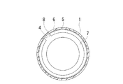
以下、本発明の構成について添付の図面を参照しながら詳細に説明する。図1及び図2は本発明の実施形態からなる空気入りタイヤを示すものである。図1において、符号CLはタイヤ赤道である。 Hereinafter, the configuration of the present invention will be described in detail with reference to the accompanying drawings. 1 and 2 show a pneumatic tire according to an embodiment of the present invention. In FIG. 1, the symbol CL is the tire equator.
図1及び図2に示すように、本実施形態の空気入りタイヤは、タイヤ周方向に延在して環状をなすトレッド部1と、トレッド部1の両側に配置された一対のサイドウォール部2と、これらサイドウォール部2のタイヤ径方向内側に配置された一対のビード部3とを備えている。
As shown in FIGS. 1 and 2, the pneumatic tire of the present embodiment includes a
一対のビード部3,3間には少なくとも1層のカーカス層10が装架されている。このカーカス層10はタイヤ径方向に配向する複数本のカーカスコードを含んでおり、カーカスコードとして有機繊維コードが好ましく使用される。カーカス層10は各ビード部3に配置されたビードコア11の廻りにタイヤ内側から外側に巻き上げられている。各ビードコア11の外周側には断面三角形状のビードフィラー12が配置されている。そして、タイヤ内表面における一対のビード部3,3間の領域にはインナーライナー層13が配置されている。
At least one
一方、トレッド部1におけるカーカス層10の外周側には複数層のベルト層14が埋設されている。ベルト層14はタイヤ周方向に対して傾斜する複数本の補強コードを含み、かつ層間で補強コードが互いに交差するように配置されている。ベルト層14において、補強コードのタイヤ周方向に対する傾斜角度は例えば10°〜40°の範囲に設定されている。ベルト層14の補強コードとしては、スチールコードが好ましく使用される。ベルト層14の外周側には、高速耐久性の向上を目的として、補強コードをタイヤ周方向に対して5°以下の角度で配列してなる少なくとも1層のベルトカバー層15が配置されている。ベルトカバー層15の補強コードとしては、ナイロンやアラミド等の有機繊維コードが好ましく使用される。
On the other hand, a plurality of belt layers 14 are embedded on the outer peripheral side of the
なお、上述したタイヤ内部構造は空気入りタイヤにおける代表的な例を示すものであるが、これに限定されるものではない。 In addition, although the tire internal structure mentioned above shows the typical example in a pneumatic tire, it is not limited to this.
上記空気入りタイヤにおいて、図1及び図2に示すように、タイヤ内面4のトレッド部1に対応する領域には、タイヤ周方向に沿って接着層5を介して吸音材6が固定されている。接着層5は、特に限定されるものではなく、例えば、接着剤や両面接着テープを使用することができる。吸音材6は、連続気泡を有する多孔質材料から構成され、その多孔質構造に基づく所定の吸音特性を有している。吸音材6の多孔質材料としては発泡ポリウレタンを用いると良い。吸音材6は撥水剤を含有しないことが望ましい。図1の実施形態において、吸音材6は、長方形の断面形状を有する1枚の帯状体6Aからなる。
In the pneumatic tire, as shown in FIGS. 1 and 2, the
本発明では、吸音材6の破断伸度y[%]が、吸音材6の温度t[℃]に対してy≧t+100かつy≦2t+440の関係を満たす。特に、y≧t+170及び/又はy≦2t+350の関係を満たすことが好ましい。このような吸音材6の温度tと破断伸度yの関係式は、吸音材6の温度tが少なくとも−20℃〜80℃の範囲にあるときに満足する。
In the present invention, the breaking elongation y [%] of the
具体的には、図3に示す斜線部の領域S1が、本発明の空気入りタイヤに採用する吸音材6の物性の範囲を示している。図3において、吸音材6の破断伸度yが、領域S1よりも下方に外れると、低温下での走行時において吸音材6の剥離や破断が生じ易くなる。一方、吸音材6の破断伸度yが領域S1よりも上方に外れると、吸音材6の硬度も共に小さくなる傾向があるので、高速走行時において吸音材6の変形が生じ易くなる。
Specifically, a hatched area S1 shown in FIG. 3 indicates a range of physical properties of the
更には、吸音材6において、上述の吸音材6の温度tと破断伸度yの関係式を満たすと共に、吸音材6の硬度x[N/314cm2]と吸音材6の破断伸度y[%]とが、130≦y≦500、y≦−21x+2770及びx>80の関係を満たすことが好ましい。特に、80<x≦120、140≦y≦490及び/又はy≦−21x+2700の関係を満たすことがより好ましく、80<x≦100、150≦y≦480及び/又はy≦−21x+2600の関係を満たすことが最も好ましい。これら吸音材6の硬度x及び破断伸度yは、標準状態(温度23℃、相対湿度50%)において測定された硬度及び破断伸度である。
Furthermore, in the
具体的には、図4に示す斜線部の領域S2が、上述の吸音材6の物性として好ましい範囲を示している。図4において、吸音材6の硬度xが、上記関係式により特定される上限値を超えると荷重耐久時においてタイヤの変形に追従することができず、吸音材6の剥離を生じる傾向があり、80N/314cm2以下であると高速走行時において吸音材6が圧縮永久歪により変形し、吸音効果を十分に得ることができない。また、吸音材6の破断伸度yが130%より小さくなると、タイヤの高変形時において吸音材6の破断が生じ易くなる傾向があり、特に、低温下においてはその傾向が顕著になる。
Specifically, the shaded area S2 shown in FIG. 4 indicates a preferable range as the physical properties of the
上述した空気入りタイヤでは、タイヤ内面4のトレッド部1に対応する領域に吸音材6を接着するにあたって、吸音材6の温度tが少なくとも−20℃〜80℃の範囲にあるときに吸音材6の破断伸度y[%]が吸音材6の温度t[℃]に対してy≧t+100かつy≦2t+440の関係を満たす吸音材6を配置しているので、高速走行時において吸音材6の吸音効果を十分に確保することができると共に、低温時において吸音材6の剥離や破断を防止することができる。
In the pneumatic tire described above, when the
上記空気入りタイヤにおいて、吸音材6の密度は10kg/m3〜30kg/m3であり、吸音材6のセル数は30個/25mm〜80個/25mmであることが好ましい。このように吸音材6の密度を設定することで、吸音材6が低密度となって軽量化を図ることができ、転がり抵抗の低減に繋がる。また、吸音材6のセル数を適度に設定することで、気泡を細かくすることができ、吸音材6の吸音効果を十分に確保することができる。
In the pneumatic tire, the density of the
吸音材6の体積は、タイヤとリムRとの間に形成される空洞部7の体積(内腔体積)に対して10%〜30%であることが好ましい。また、吸音材6の幅がタイヤ接地幅に対して30%〜90%であることがより好ましい。これにより、吸音材6の吸音効果を十分に確保することでき、静穏性の向上に繋がる。ここで、吸音材6の体積がタイヤの内腔体積に対して10%を下回ると吸音効果を適切に得ることができない。また、吸音材6の体積がタイヤの内腔体積に対して30%を超えると空洞共鳴現象による騒音の低減効果が一定となり、より一層の低減効果が望めなくなる。
The volume of the
吸音材6は、図2に示すように、タイヤ周方向の少なくとも1箇所に欠落部8を有することが好ましい。欠落部8とはタイヤ周上で吸音材6が存在しない部分である。吸音材6に欠落部8を設けることにより、タイヤのインフレートによる膨張や接地転動に起因する接着面のせん断ひずみに長時間耐えることができ、吸音材6の接着面に生じるせん断歪みを効果的に緩和することが可能になる。このような欠落部8はタイヤ周上で1箇所又は3〜5箇所設けるのが良い。つまり、欠落部8をタイヤ周上の2箇所に設けると質量アンバランスに起因してタイヤユニフォミティの悪化が顕著になり、欠落部8をタイヤ周上の6箇所以上に設けると製造コストの増大が顕著になる。
As shown in FIG. 2, the
なお、欠落部8をタイヤ周上の2箇所以上に設ける場合、吸音材6がタイヤ周方向に途切れることになるが、そのような場合であっても、例えば、両面接着テープからなる接着層5のような他の積層物で複数の吸音材6を互いに連結するようにすれば、これら吸音材6を一体的な部材として取り扱うことができるため、タイヤ内面4への貼り付け作業を容易に行うことができる。
In addition, when providing the
上記空気入りタイヤにおいて、接着層5は両面接着テープからなり、接着層5の総厚さは10μm〜150μmであることが好ましい。このように接着層5を構成することで、成形時の変形に対する追従性を確保することができる。ここで、接着層5の総厚さが10μm未満であると両面接着テープの強度が不足して吸音材6との接着性が十分に確保できず、接着層5の総厚さが150μmを超えると高速走行時に放熱を阻害するため高速耐久性が悪化し易い。
In the pneumatic tire, the
図5は本発明の実施形態からなる空気入りタイヤの変形例を示すものである。図5に示すように、トレッド部1には、タイヤ周方向に延びる周方向溝20が2本以上形成される。これら周方向溝20によって、タイヤ幅方向に隣り合う2本の周方向溝20に挟まれて区画された陸部21が1列以上、タイヤ幅方向最外側に位置する周方向溝20のそれぞれのタイヤ幅方向外側に区画されたショルダー陸部22が2列(タイヤ幅方向両側に1列ずつ)形成される。陸部21は、タイヤ全周に亘って連続的に延在してタイヤ赤道CL上に配置されたセンター陸部21cを必ず含む。
FIG. 5 shows a modification of the pneumatic tire according to the embodiment of the present invention. As shown in FIG. 5, the
ここで、図1に示す実施形態では、吸音材6が長方形の断面形状を有する1枚の帯状体6Aからなり、吸音材6を構成する帯状体6Aがタイヤ赤道CLを跨ぐように配置されている。これに対して、図5に示す実施形態では、吸音材6が長方形の断面形状を有する第一の帯状体6Aと第二の帯状体6Bからなり、吸音材6を構成する第一の帯状体6Aについてはセンター陸部21cのタイヤ幅方向の一方側の端部からタイヤ幅方向の他方側に向かってセンター陸部21cの幅Wの40%の位置よりもタイヤ幅方向の一方側に配置され、吸音材6を構成する第二の帯状体6Bについてはセンター陸部21cのタイヤ幅方向の他方側の端部からタイヤ幅方向の一方側に向かってセンター陸部21cの幅Wの40%の位置よりもタイヤ幅方向の他方側に配置され、かつ、第一の帯状体6Aと第二の帯状体6Bとの離間距離Dがセンター陸部21cの幅Wの60%以上に設定される。また、帯状体6A,6Bの各々とセンター陸部21cとの重複量L(第一の帯状体6Aの重複量L1と第二の帯状体6Bの重複量L2との和)がセンター陸部21cの幅Wの40%以下になるように設定されている。
Here, in the embodiment shown in FIG. 1, the
上述のように、第一の帯状体6Aと第二の帯状体6Bとからなる一対の吸音材6を採用し、この一対の吸音材6を離間させて、トレッド部1において最も発熱し易く、吸音材6が直貼りされた際に蓄熱を生じ易いセンター陸部21cの内面側を避けた位置に配置するようにしているので、高速走行時における蓄熱を効果的に抑制し、高速耐久性を高めることができ、騒音性能と高速耐久性とをバランスよく改善することができる。
As described above, the pair of
なお、第一/第二の帯状体6A,6Bがセンター陸部21cのタイヤ幅方向の一方側/他方側の端部からタイヤ幅方向の他方側/一方側に向かってセンター陸部21cの幅Wの40%の位置よりもタイヤ幅方向の一方側/他方側に配置される構造は、第一/第二の帯状体6A,6Bのタイヤ幅方向内側の端部がセンター陸部21cのタイヤ幅方向の一方側/他方側の端部からタイヤ幅方向の他方側/一方側に向かってセンター陸部21cの幅Wの40%の位置と一致する場合も含む。
The first / second belt-
タイヤサイズ275/35ZR20で、タイヤ周方向に延在して環状をなすトレッド部と、トレッド部の両側に配置された一対のサイドウォール部と、これらサイドウォール部のタイヤ径方向内側に配置された一対のビード部とを備えた空気入りタイヤにおいて、異なる物性を有する吸音材A〜Hを、トレッド部の内面にタイヤ周方向に沿って接着層を介して貼り付け、比較例1〜4及び実施例1〜4のタイヤを製作した。また、各試験タイヤに貼り付けた吸音材A〜Hについて、吸音材の硬度[N/314cm2]、吸音材の密度[kg/m3]及び吸音材のセル数[個/25mm]を表1のように設定した。 In tire size 275 / 35ZR20, the tread portion that extends in the tire circumferential direction and has an annular shape, the pair of sidewall portions that are disposed on both sides of the tread portion, and the inner side in the tire radial direction of these sidewall portions In a pneumatic tire provided with a pair of bead parts, sound absorbing materials A to H having different physical properties are attached to the inner surface of the tread part via an adhesive layer along the tire circumferential direction, and Comparative Examples 1 to 4 and the implementation. Tires of Examples 1 to 4 were manufactured. For the sound absorbing materials A to H attached to each test tire, the sound absorbing material hardness [N / 314 cm 2 ], the sound absorbing material density [kg / m 3 ] and the number of sound absorbing material cells [pieces / 25 mm] are shown. 1 was set.
これら試験タイヤにおいて、吸音材の温度が−20℃、23℃、80℃の場合における各吸音材A〜Hの破断伸度[%]を測定し、その結果を表1に併せて示した。また、図3において、比較例1〜4のタイヤに貼り付けた吸音材A〜Dの物性をそれぞれ三角形の印で示し、実施例1〜4のタイヤに貼り付けた吸音材E〜Hの物性をそれぞれ丸形の印で示した。更に、各試験タイヤについて、下記試験方法により、キャンバー角付きの高速耐久性及び低温耐久性を評価し、その結果を表1に併せて示した。 In these test tires, the breaking elongation [%] of each of the sound absorbing materials A to H when the temperature of the sound absorbing material was −20 ° C., 23 ° C., and 80 ° C. was measured, and the results are also shown in Table 1. Moreover, in FIG. 3, the physical properties of the sound absorbing materials A to D attached to the tires of Comparative Examples 1 to 4 are indicated by triangular marks, respectively, and the physical properties of the sound absorbing materials E to H attached to the tires of Examples 1 to 4 are shown. Is indicated by a round mark. Further, each test tire was evaluated for high speed durability and low temperature durability with a camber angle by the following test method, and the results are also shown in Table 1.
キャンバー角度付きの高速耐久性:
各試験タイヤをそれぞれリムサイズ20×9Jのホイールに組み付け、走行速度330km/h、空気圧290kPa、荷重6kN、ネガティブキャンバー角度−3°、走行距離400kmの条件でドラム試験機にて走行試験を実施した後、吸音材の圧縮永久歪による変形の有無を目視により確認した。
High speed durability with camber angle:
After each test tire was assembled on a wheel with a rim size of 20 × 9 J, and a running test was performed with a drum tester under conditions of a running speed of 330 km / h, an air pressure of 290 kPa, a load of 6 kN, a negative camber angle of −3 °, and a running distance of 400 km. The presence or absence of deformation due to compression set of the sound absorbing material was confirmed visually.
低温耐久性:
各試験タイヤをそれぞれリムサイズ20×9 1/2Jのホイールに組み付け、温度−20℃、走行速度81km/h、空気圧160kPa、荷重5kN、走行距離6,480kmの条件でドラム試験機にて走行試験を実施した後、吸音材の破断の有無を目視により確認した。
Low temperature durability:
Each test tire is assembled to a wheel with a rim size of 20 × 9 1 / 2J, and a running test is performed with a drum testing machine under the conditions of a temperature of −20 ° C., a running speed of 81 km / h, an air pressure of 160 kPa, a load of 5 kN and a running distance of 6,480 km. After the implementation, the sound absorbing material was visually checked for breakage.

この表1から判るように、実施例1〜4のタイヤに貼り付けた吸音材E〜Hは、本発明で規定する吸音材の温度と破断伸度の関係式を満たすものである。比較例1との対比において、実施例1〜4の空気入りタイヤは低温耐久性が改善されていた。また、比較例2との対比において、実施例1〜4の空気入りタイヤはキャンバー角度付きの高速耐久性が改善されていた。 As can be seen from Table 1, the sound absorbing materials E to H attached to the tires of Examples 1 to 4 satisfy the relational expression between the temperature of the sound absorbing material and the breaking elongation defined in the present invention. In comparison with Comparative Example 1, the low temperature durability of the pneumatic tires of Examples 1 to 4 was improved. Further, in comparison with Comparative Example 2, the pneumatic tires of Examples 1 to 4 had improved high-speed durability with a camber angle.
比較例3においては、その吸音材Cが本発明で規定する吸音材の温度と破断伸度の関係式を−20℃の場合において満たしておらず、また、低温耐久性の試験において吸音材の破断が確認された。比較例4においては、その吸音材Dが本発明で規定する吸音材の温度と破断伸度の関係式を80℃の場合において満たしておらず、また、キャンバー角付きの高速耐久性の試験において吸音材の変形が確認された。 In Comparative Example 3, the sound absorbing material C does not satisfy the relational expression between the temperature of the sound absorbing material defined in the present invention and the elongation at break at −20 ° C., and in the low temperature durability test, the sound absorbing material C Breaking was confirmed. In Comparative Example 4, the sound absorbing material D does not satisfy the relational expression between the temperature of the sound absorbing material defined in the present invention and the elongation at break at 80 ° C., and in a high-speed durability test with a camber angle. The deformation of the sound absorbing material was confirmed.
1 トレッド部
2 サイドウォール部
3 ビード部
4 タイヤ内面
5 接着層
6 吸音材
6A,6B 帯状体
7 空洞部
8 欠落部
20 周方向溝
21 陸部
21c センター陸部
CL タイヤ赤道
R リム
DESCRIPTION OF
Claims (7)
前記トレッド部の内面にタイヤ周方向に沿って接着層を介して吸音材が固定され、前記吸音材の温度t[℃]が少なくとも−20℃〜80℃の範囲にあるときに前記吸音材の破断伸度y[%]が該吸音材の温度t[℃]に対してy≧t+100かつy≦2t+440の関係を満たし、前記吸音材のセル数が30個/25mm〜80個/25mmであり、前記接着層が両面接着テープからなり、前記接着層の総厚さが10μm〜150μmであることを特徴とする空気入りタイヤ。 An annular tread portion extending in the tire circumferential direction, a pair of sidewall portions disposed on both sides of the tread portion, and a pair of bead portions disposed on the inner side in the tire radial direction of the sidewall portions. In the provided pneumatic tire,
When the sound absorbing material is fixed to the inner surface of the tread portion via an adhesive layer along the tire circumferential direction, and the temperature t [° C.] of the sound absorbing material is at least in the range of −20 ° C. to 80 ° C. meets a relationship of y ≧ t + 100 and y ≦ 2t + 440 breaking elongation y [%] is for the temperature t [° C.] of the sound absorbing material, the number of cells of said sound absorbing material at 30 / 25Mm~80 pieces / 25mm The pneumatic tire is characterized in that the adhesive layer is made of a double-sided adhesive tape, and the total thickness of the adhesive layer is 10 μm to 150 μm .
Priority Applications (5)
| Application Number | Priority Date | Filing Date | Title |
|---|---|---|---|
| JP2017202643A JP6583383B2 (en) | 2017-10-19 | 2017-10-19 | Pneumatic tire |
| CN201880067470.6A CN111225805B (en) | 2017-10-19 | 2018-10-17 | Pneumatic tire |
| US16/757,352 US20210188020A1 (en) | 2017-10-19 | 2018-10-17 | Pneumatic Tire |
| PCT/JP2018/038738 WO2019078281A1 (en) | 2017-10-19 | 2018-10-17 | Pneumatic tyre |
| DE112018004600.1T DE112018004600T5 (en) | 2017-10-19 | 2018-10-17 | tire |
Applications Claiming Priority (1)
| Application Number | Priority Date | Filing Date | Title |
|---|---|---|---|
| JP2017202643A JP6583383B2 (en) | 2017-10-19 | 2017-10-19 | Pneumatic tire |
Publications (2)
| Publication Number | Publication Date |
|---|---|
| JP2019073245A JP2019073245A (en) | 2019-05-16 |
| JP6583383B2 true JP6583383B2 (en) | 2019-10-02 |
Family
ID=66174044
Family Applications (1)
| Application Number | Title | Priority Date | Filing Date |
|---|---|---|---|
| JP2017202643A Active JP6583383B2 (en) | 2017-10-19 | 2017-10-19 | Pneumatic tire |
Country Status (5)
| Country | Link |
|---|---|
| US (1) | US20210188020A1 (en) |
| JP (1) | JP6583383B2 (en) |
| CN (1) | CN111225805B (en) |
| DE (1) | DE112018004600T5 (en) |
| WO (1) | WO2019078281A1 (en) |
Families Citing this family (2)
| Publication number | Priority date | Publication date | Assignee | Title |
|---|---|---|---|---|
| JP7529974B2 (en) | 2020-04-13 | 2024-08-07 | 横浜ゴム株式会社 | Pneumatic tires |
| JP7534610B2 (en) | 2020-07-01 | 2024-08-15 | 横浜ゴム株式会社 | Pneumatic tires |
Family Cites Families (23)
| Publication number | Priority date | Publication date | Assignee | Title |
|---|---|---|---|---|
| CN100493932C (en) | 2003-08-04 | 2009-06-03 | 横滨橡胶株式会社 | Low noise pneumatic tire |
| JP3787343B2 (en) * | 2003-11-07 | 2006-06-21 | 住友ゴム工業株式会社 | Pneumatic tire and rim assembly |
| JP3934621B2 (en) * | 2004-03-16 | 2007-06-20 | 住友ゴム工業株式会社 | Pneumatic tire and rim assembly |
| US20070246142A1 (en) * | 2004-05-25 | 2007-10-25 | Makoto Ishiyama | Pneumatic Tire |
| JP4330550B2 (en) * | 2005-04-28 | 2009-09-16 | 住友ゴム工業株式会社 | Pneumatic tire and rim assembly |
| JP2007112395A (en) * | 2005-10-24 | 2007-05-10 | Sumitomo Rubber Ind Ltd | Assembly of pneumatic tire and rim |
| JP4575874B2 (en) * | 2005-11-18 | 2010-11-04 | 横浜ゴム株式会社 | Soft polyurethane foam for tire, noise reduction device and tire |
| JP5267288B2 (en) | 2008-05-09 | 2013-08-21 | 横浜ゴム株式会社 | Tire noise reduction device |
| JP4636126B2 (en) * | 2008-06-17 | 2011-02-23 | 横浜ゴム株式会社 | Pneumatic tire manufacturing method |
| JP4525800B2 (en) * | 2008-06-20 | 2010-08-18 | 横浜ゴム株式会社 | Tire noise reduction device and pneumatic tire equipped with the same |
| DE202008009008U1 (en) * | 2008-07-03 | 2008-09-04 | Recticel N.V. | vehicle tires |
| JP4992937B2 (en) * | 2009-05-25 | 2012-08-08 | 横浜ゴム株式会社 | Pneumatic tire |
| FR3005959B1 (en) * | 2013-05-23 | 2015-06-19 | Michelin & Cie | INTERNAL PNEUMATIC MIXTURE WITH ENHANCED CRACKING RESISTANCE |
| CN105722693B (en) * | 2013-11-21 | 2017-12-12 | 横滨橡胶株式会社 | Pneumatic tire |
| JP6120887B2 (en) * | 2014-04-25 | 2017-04-26 | クムホ タイヤ カンパニー インコーポレイテッドKumho Tire Co.,Inc. | Cavity resonance sound reduction tire |
| JP6444671B2 (en) * | 2014-09-12 | 2018-12-26 | 株式会社ブリヂストン | Pneumatic tire |
| JP6619343B2 (en) * | 2014-09-12 | 2019-12-11 | 株式会社ブリヂストン | Pneumatic tire |
| JP6446936B2 (en) * | 2014-09-18 | 2019-01-09 | 横浜ゴム株式会社 | Tire noise reduction device and pneumatic tire |
| CN105415770B (en) * | 2015-11-25 | 2017-11-14 | 中国铁道科学研究院金属及化学研究所 | A kind of damping-constraining noise reducing plate and preparation method thereof |
| US20190092103A1 (en) * | 2016-03-25 | 2019-03-28 | Pirelli Tyre S.P.A. | Soundproof self-sealing tyre for vehicle wheels |
| JP2018141839A (en) * | 2017-02-27 | 2018-09-13 | 日東電工株式会社 | Acoustic absorbent |
| KR102484817B1 (en) * | 2017-03-06 | 2023-01-04 | 스미토모 고무 코교 카부시키카이샤 | pneumatic tire |
| US20200164701A1 (en) * | 2017-08-22 | 2020-05-28 | Sumitomo Rubber Industries, Ltd. | Pneumatic tyre |
-
2017
- 2017-10-19 JP JP2017202643A patent/JP6583383B2/en active Active
-
2018
- 2018-10-17 WO PCT/JP2018/038738 patent/WO2019078281A1/en active Application Filing
- 2018-10-17 DE DE112018004600.1T patent/DE112018004600T5/en active Pending
- 2018-10-17 US US16/757,352 patent/US20210188020A1/en active Pending
- 2018-10-17 CN CN201880067470.6A patent/CN111225805B/en active Active
Also Published As
| Publication number | Publication date |
|---|---|
| US20210188020A1 (en) | 2021-06-24 |
| CN111225805B (en) | 2022-08-26 |
| JP2019073245A (en) | 2019-05-16 |
| DE112018004600T5 (en) | 2020-05-28 |
| WO2019078281A1 (en) | 2019-04-25 |
| CN111225805A (en) | 2020-06-02 |
Similar Documents
| Publication | Publication Date | Title |
|---|---|---|
| JP6519471B2 (en) | Pneumatic tire | |
| JP6551228B2 (en) | Pneumatic tire | |
| JP6904355B2 (en) | Run flat tire | |
| JP6658035B2 (en) | Pneumatic tire | |
| JP6536402B2 (en) | Pneumatic tire | |
| JP6583382B2 (en) | Pneumatic tire | |
| JP7243769B2 (en) | pneumatic tire | |
| US11021022B2 (en) | Pneumatic tire | |
| JP6583383B2 (en) | Pneumatic tire | |
| JP6927221B2 (en) | Pneumatic tires | |
| JP6672718B2 (en) | Pneumatic tire | |
| JP6981227B2 (en) | Pneumatic tires | |
| JP6939466B2 (en) | Pneumatic tires | |
| JP2012236521A (en) | Pneumatic tire | |
| JP6939777B2 (en) | Pneumatic tires |
Legal Events
| Date | Code | Title | Description |
|---|---|---|---|
| A621 | Written request for application examination |
Free format text: JAPANESE INTERMEDIATE CODE: A621 Effective date: 20181012 |
|
| A131 | Notification of reasons for refusal |
Free format text: JAPANESE INTERMEDIATE CODE: A131 Effective date: 20190108 |
|
| A521 | Request for written amendment filed |
Free format text: JAPANESE INTERMEDIATE CODE: A523 Effective date: 20190222 |
|
| TRDD | Decision of grant or rejection written | ||
| A01 | Written decision to grant a patent or to grant a registration (utility model) |
Free format text: JAPANESE INTERMEDIATE CODE: A01 Effective date: 20190806 |
|
| A61 | First payment of annual fees (during grant procedure) |
Free format text: JAPANESE INTERMEDIATE CODE: A61 Effective date: 20190819 |
|
| R150 | Certificate of patent or registration of utility model |
Ref document number: 6583383 Country of ref document: JP Free format text: JAPANESE INTERMEDIATE CODE: R150 |
|
| R250 | Receipt of annual fees |
Free format text: JAPANESE INTERMEDIATE CODE: R250 |
|
| S531 | Written request for registration of change of domicile |
Free format text: JAPANESE INTERMEDIATE CODE: R313531 |
|
| R350 | Written notification of registration of transfer |
Free format text: JAPANESE INTERMEDIATE CODE: R350 |
|
| R250 | Receipt of annual fees |
Free format text: JAPANESE INTERMEDIATE CODE: R250 |
|
| R250 | Receipt of annual fees |
Free format text: JAPANESE INTERMEDIATE CODE: R250 |