EP1529256B1 - Dispositif de commande a entrainement direct avec retroaction haptique - Google Patents
Dispositif de commande a entrainement direct avec retroaction haptique Download PDFInfo
- Publication number
- EP1529256B1 EP1529256B1 EP03767227A EP03767227A EP1529256B1 EP 1529256 B1 EP1529256 B1 EP 1529256B1 EP 03767227 A EP03767227 A EP 03767227A EP 03767227 A EP03767227 A EP 03767227A EP 1529256 B1 EP1529256 B1 EP 1529256B1
- Authority
- EP
- European Patent Office
- Prior art keywords
- output shaft
- lamination
- freedom
- motor
- coil
- Prior art date
- Legal status (The legal status is an assumption and is not a legal conclusion. Google has not performed a legal analysis and makes no representation as to the accuracy of the status listed.)
- Expired - Lifetime
Links
Images

Classifications
-
- H—ELECTRICITY
- H02—GENERATION; CONVERSION OR DISTRIBUTION OF ELECTRIC POWER
- H02K—DYNAMO-ELECTRIC MACHINES
- H02K41/00—Propulsion systems in which a rigid body is moved along a path due to dynamo-electric interaction between the body and a magnetic field travelling along the path
- H02K41/02—Linear motors; Sectional motors
- H02K41/03—Synchronous motors; Motors moving step by step; Reluctance motors
- H02K41/031—Synchronous motors; Motors moving step by step; Reluctance motors of the permanent magnet type
-
- G—PHYSICS
- G05—CONTROLLING; REGULATING
- G05G—CONTROL DEVICES OR SYSTEMS INSOFAR AS CHARACTERISED BY MECHANICAL FEATURES ONLY
- G05G9/00—Manually-actuated control mechanisms provided with one single controlling member co-operating with two or more controlled members, e.g. selectively, simultaneously
- G05G9/02—Manually-actuated control mechanisms provided with one single controlling member co-operating with two or more controlled members, e.g. selectively, simultaneously the controlling member being movable in different independent ways, movement in each individual way actuating one controlled member only
- G05G9/04—Manually-actuated control mechanisms provided with one single controlling member co-operating with two or more controlled members, e.g. selectively, simultaneously the controlling member being movable in different independent ways, movement in each individual way actuating one controlled member only in which movement in two or more ways can occur simultaneously
- G05G9/047—Manually-actuated control mechanisms provided with one single controlling member co-operating with two or more controlled members, e.g. selectively, simultaneously the controlling member being movable in different independent ways, movement in each individual way actuating one controlled member only in which movement in two or more ways can occur simultaneously the controlling member being movable by hand about orthogonal axes, e.g. joysticks
-
- H—ELECTRICITY
- H02—GENERATION; CONVERSION OR DISTRIBUTION OF ELECTRIC POWER
- H02K—DYNAMO-ELECTRIC MACHINES
- H02K26/00—Machines adapted to function as torque motors, i.e. to exert a torque when stalled
-
- G—PHYSICS
- G05—CONTROLLING; REGULATING
- G05G—CONTROL DEVICES OR SYSTEMS INSOFAR AS CHARACTERISED BY MECHANICAL FEATURES ONLY
- G05G9/00—Manually-actuated control mechanisms provided with one single controlling member co-operating with two or more controlled members, e.g. selectively, simultaneously
- G05G9/02—Manually-actuated control mechanisms provided with one single controlling member co-operating with two or more controlled members, e.g. selectively, simultaneously the controlling member being movable in different independent ways, movement in each individual way actuating one controlled member only
- G05G9/04—Manually-actuated control mechanisms provided with one single controlling member co-operating with two or more controlled members, e.g. selectively, simultaneously the controlling member being movable in different independent ways, movement in each individual way actuating one controlled member only in which movement in two or more ways can occur simultaneously
- G05G9/047—Manually-actuated control mechanisms provided with one single controlling member co-operating with two or more controlled members, e.g. selectively, simultaneously the controlling member being movable in different independent ways, movement in each individual way actuating one controlled member only in which movement in two or more ways can occur simultaneously the controlling member being movable by hand about orthogonal axes, e.g. joysticks
- G05G2009/04766—Manually-actuated control mechanisms provided with one single controlling member co-operating with two or more controlled members, e.g. selectively, simultaneously the controlling member being movable in different independent ways, movement in each individual way actuating one controlled member only in which movement in two or more ways can occur simultaneously the controlling member being movable by hand about orthogonal axes, e.g. joysticks providing feel, e.g. indexing means, means to create counterforce
-
- H—ELECTRICITY
- H02—GENERATION; CONVERSION OR DISTRIBUTION OF ELECTRIC POWER
- H02K—DYNAMO-ELECTRIC MACHINES
- H02K1/00—Details of the magnetic circuit
- H02K1/06—Details of the magnetic circuit characterised by the shape, form or construction
- H02K1/12—Stationary parts of the magnetic circuit
- H02K1/14—Stator cores with salient poles
- H02K1/146—Stator cores with salient poles consisting of a generally annular yoke with salient poles
-
- H—ELECTRICITY
- H02—GENERATION; CONVERSION OR DISTRIBUTION OF ELECTRIC POWER
- H02K—DYNAMO-ELECTRIC MACHINES
- H02K16/00—Machines with more than one rotor or stator
-
- H—ELECTRICITY
- H02—GENERATION; CONVERSION OR DISTRIBUTION OF ELECTRIC POWER
- H02K—DYNAMO-ELECTRIC MACHINES
- H02K2201/00—Specific aspects not provided for in the other groups of this subclass relating to the magnetic circuits
- H02K2201/03—Machines characterised by aspects of the air-gap between rotor and stator
-
- H—ELECTRICITY
- H02—GENERATION; CONVERSION OR DISTRIBUTION OF ELECTRIC POWER
- H02K—DYNAMO-ELECTRIC MACHINES
- H02K2201/00—Specific aspects not provided for in the other groups of this subclass relating to the magnetic circuits
- H02K2201/18—Machines moving with multiple degrees of freedom
Definitions
- the present invention relates to a multiple degree-of-freedom motor according to the preamble of claim 1. Generally, it relates to a force feedback motor assembly that provides an output in one or more degrees of freedom for use in joystick and other applications, and more particularly, to an improved force feedback joystick.
- the U.S. patent application No. 2002/0053849 discloses a motor having an output shaft movable in multiple degrees of freedom according to the preamble of claim 1.
- the motor comprises four lamination stacks arranged symmetrically about the output shaft at regular 90 degree intervals.
- the lamination stacks of the two pairs of stacks are disposed diametrically opposite one another.
- the European patent application EP 0 938 035 discloses an electro-mechanical operating device by which four poles defining a stator are arranged about a spherical rotor. The individual poles can be adjusted in their position about the rotor in radial and angular direction.
- German patent application DE 195 01 439 discloses an electro-mechanical operating device by which four poles defining a stator are arranged symmetrically at 90 degrees intervals about a rotor. The poles of each of the two pairs of poles are disposed opposite one another.
- the European patent application EP 0 113 267 A1 discloses an electro-mechanical converter including a ferromagnetic sphere acting as the rotor surrounded by magnetic means in the form of three lamination stacks.
- the purpose of the converter is to provide three degrees of freedom for adjusting the position a body with respect to a stationary frame at a desired solid angle.
- Various force feedback motor designs providing multiple degrees of freedom are known in the art for use in a wide variety of applications. For example, multiple degrees of freedom in motor output are particularly useful in linear actuation and positioning applications.
- Another application in which such motors may be used is in joystick applications for real control of an associated apparatus, e.g., direct control of an aircraft, wheelchair, or other vehicle, or for simulation apparatus control, e.g. video games, flight simulation, virtual reality simulation, etc.
- a control system may be provided for sensing a user's manipulation of a joystick, i.e., the motor output shaft, and providing a signal for controlling the application.
- the force feedback can be used to counteract the effect of the acceleration induced forces on the hand and thus improve controllability and safety of the vehicle.
- force feedback is necessary to realistically simulate physical objects; for example, if a user touches a pen to a table, the user should feel the impact of the pen on the table.
- An effective human/computer interface such as a joystick, not only acts as an input device for tracking motion, but also as an output device for producing realistic tactile sensations.
- An interface that accurately responds to signals having fast changes and a broad range of frequencies as well as providing such signals accurately to a control system, is therefore desirable in these and other applications.
- joysticks and other interface devices can be used to provide force feedback to a user playing a video game or experiencing a simulation for entertainment purposes.
- a computer system can convey to the user the physical sensation of colliding into a wall, moving through a liquid, driving over a bumpy road, and other sensations. The user can thus experience an entire sensory dimension in the gaming experience that was previously absent.
- Force feedback interfaces can provide a whole new modality for humancomputer interaction.
- the prior art devices require high-speed control signals from a controlling computer for stability, which usually requires more expensive and complex electronics.
- the prior art devices are typically large and noisy. These factors provide many obstacles to the would-be manufacturer of force-feedback interfaces to the home computer market.
- DC (direct current) motors which are commonly used in prior art devices, suffer from several disadvantages that make them unsuitable for many applications.
- DC motors do not have inherent positional control and require additional sensors (e.g., optical) to determine the position of the rotor. Such sensors may malfunction because of dust or wear particles created by the mechanical braking system. This can have a negative effect on achieving the accuracy and precision of movement required in certain applications.
- DC motors also lack braking control and must incorporate additional mechanisms, such as gearing, clutches, and a solenoid brake to control speed and/or stop the rotor in desired positions. These additional components increase the mechanical complexity of the system and are susceptible to wear and tear. Thus, the reliability of a DC motor system is frequently an issue.
- the present invention provides a reliable and cost-efficient direct drive (i.e., no transmission subsystem) force feedback motor suitable for joystick applications, allowing multiple degrees of output freedom, requiring no coil commutation, and permitting compact packaging.
- a multiple degree-of-freedom motor is provided as defined in claim 1.
- Energization of the coil of the first lamination stack establishes a first magnetic field to urge the output shaft to rotate in a first plane
- energization of the coil of the second lamination stack establishes a second magnetic field to urge the output shaft to rotate in a second plane substantially orthogonal to the first plane.
- the first degree of freedom may be substantially perpendicular to a longitudinal axis of wires of one coil associated with the first degree of freedom
- the second degree of freedom may be substantially perpendicular to a longitudinal axis of wires of the other coil.
- the method may further comprise: disposing a third stator coil adjacent the output shaft; fixing the rotor so as to include at least one magnet disposed thereon and being movable in a direction defining a third degree of freedom; and urging the output shaft to rotate in a third plane by energizing the third stator coil, wherein the energization of the third stator coil establishes a third magnetic field to urge the output shaft to rotate in a third plane substantially orthogonal to each of the first and second planes.
- a lamination stack for use in a stator of a motor having an output shaft may comprise a plurality of laminations stacked flat against one another and parallel to one another, wherein the laminations near the edge of the stack are disposed slightly closer to the output shaft to form a stepped concave surface about the longitudinal axis of the output shaft in a plane orthogonal to a side surface of the plurality of laminations.
- the shape of the stepped concave surface of the plurality of laminations about an equator of the plurality of laminations may approximate an arc having a constant radius in a plane orthogonal to a side surface of the plurality of laminations.
- the multiple degree-of-freedom motor comprises two lamination stacks, where the lamination stacks are disposed perpendicular to one another, each lamination stack having a curved interior are surface and a coil wound thereon.
- the laminations of the first lamination stack and second lamination stack are substantially parallel to one another.
- Energization of the coil of the first lamination stack may establish a first magnetic field to urge the output shaft to rotate in a first plane
- energization of the coil of the second lamination stack may establish a second magnetic field to urge the output shaft to rotate in a second plane.
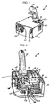
- a motor assembly 10 is configured for operation as a joystick, which may provide force feedback to a user through the joystick handle 20.
- a motor assembly 10 consistent with the invention may be used in a wide variety of applications. The descriptions provided herein relate to use of an assembly in a joystick configuration are provided, therefore, by way of illustration but not of limitation.
- the assembly 10 generally includes a housing 17 having a plurality of ventilation apertures 19 formed therein.
- the housing 17 contains control circuitry (not shown in Figure 1 ) for a moving joystick handle 20, a cooling fan 19, a communications interface port 21, and a power supply interface port 23.
- the moving joystick handle 20 projects from and is coupled to a shaft 22 disposed within an opening 29 in the housing 17 and may have disposed therein or thereon one or more buttons or switches, e.g., thumb buttons 13 or a trigger 15.
- the handle 20 and shaft 22 may serve as either an input device, an output device, or both.
- the joystick handle 20 preferably has a grip as low as possible (i.e., as close to the housing 17 as possible), as it is anticipated that motor assemblies consistent with the invention may be utilized in physically small spaces and/or may be disposed at both the left- and right-hand sides of a user.
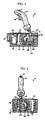
- a pair of lamination stacks 25, 27 defines the stator of the motor.
- Each of the lamination stacks 25, 27 contains at least one respective coil 16, 18 configured to carry electrical current provided from a power supply (not shown), e.g., connected via the power supply interface port 23 and cards '31, 33, and 35.
- the lamination stacks may have spherical or pseudo-spherical inner surfaces (i.e., the surfaces facing the handle 20) with parallel horizontal slots 37, as shown in Figure 2 .
- a plurality of laminations preferably identical, are all stacked flat against each other (parallel to each other) and the laminations near the edge of the stack are disposed slightly closer to the shaft 22 of the handle 20 to form a stepped concave surface about the longitudinal axis of the output shaft 22 in a plane orthogonal to a side surface of the plurality of laminations.
- the laminations may be spaced by an insulator.
- the shape of the stepped concave surface of the plurality of laminations about an equator of the plurality of laminations approximates an arc having a constant radius in a plane orthogonal to a side surface of the plurality of laminations.
- the use of the laminations arranged in such a manner results in an inner stator surface that is almost, but not quite spherical (thus, the term pseudo-spherical). This arrangement maintains an air gap that is almost, but not quite, constant which is advantageous to motor operation.
- This pseudo-spherical design also provides advantages in terms of manufacturing ease.
- the lamination stack 25 may comprise a plurality of parallel horizontally-oriented slots S, in one embodiment.
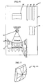
- Figure 5B illustrated an alternative embodiment, in which the lamination stacks 25' comprise a plurality of radially-oriented (rather than parallel) slots, wherein the individual stator laminations of the lamination stacks are oriented radially about the output shaft 22, parallel to the longitudinal axis of the output shaft 22.
- the lamination stacks may comprise a plurality of laminations radially disposed about a center point, with a plane of each lamination extending through said center point.
- Each lamination may be separated by one or more wedge-shaped spacers and/or insulators, to make the distance between adjacent laminations greater along the outside surface of the lamination stack than along the inside surface of the lamination stack.
- These laminations may be all cut identically with an arcuate inner surface perpendicular to the plane of the laminations, as shown in Figure 5A , and the laminations may have a plurality of radially oriented slots S.
- the lamination stacks have no slots formed therein.
- slotless lamination stacks 25", 27" are employed, since no slots are necessary at all. The result is that cogging due to the permanent magnet can be eliminated in this manner.
- each coil 16, 18 is wound horizontally in a bundle of turns. It is contemplated that there may be greater than 100 turns in each bundle, such that the total number of turns may exceed 600.
- the coils 16, 18 are wound out the back of each respective lamination stack 25, 27 (away from the handle 20) and have a substantially rectangular cross-section.
- the coils 16, 18 are disposed substantially orthogonally with respect to one other.
- the moving joystick handle 20 has a shaft 22 extending from a bottom thereof.
- the shaft 22 is attached to the housing 17 at a joint 26 so that the shaft may pivot within an opening 29 (shown in Figure 1 ) in the housing 17.
- the joint 26, i.e., the mechanical system to hold the joystick to the base and permit movement in two or more degrees of freedom, may comprise one of several designs, including universal joints, ball joints, and two-degree-of-freedom gimbals. However, universal joints are preferred for use with the system due to their durability, simplicity and widespread use and availability.
- the described system of constraint serves as a simple embodiment. It is to be understood, however, that a variety of means for constraining the moving components to the desired degrees of freedom may be employed.
- a plurality of control circuits e.g., a circuit 31 for controlling and/or detecting a first degree of freedom movement, a circuit 33 for controlling and/or detecting a second degree of freedom movement, and a circuit 35 for interfacing with a computer via a communications port 21, e.g., Universal Serial Bus (USB).
- the position of the shaft 22 can be sensed by, e.g., potentiometers (not shown) for sensing the displacement of the shaft 22 along each degree of freedom.
- potentiometers not shown
- a variety of means for sensing the rotational position of these elements, and therefore determining the position of the shaft 22 may be employed.
- potentiometers may be coupled to the shafts to provide varying resistance depending on the position of the shaft.
- a control application can provide an output signal that varies according to the resistance provided by the potentiometers so that the output of the application is related in a known manner to the position of the shaft. It is to be understood, however, that a variety of means for providing shaft position information may be employed.
- linkage backiron 38 having an "L" shape with its two arms turned down is arranged so that magnets 40 and 42 are disposed on the downward sloping arms of linkage backiron 38.
- This two-arm rocker design results in a low rotation moment of inertia, thereby being advantageous relative to prior art four-arm rockers or other designs employing transmission systems which magnify the rotational inertia by the transmission ratio squared (raised to the second power).
- Low mechanical inertia is desirable for high frequency responsiveness.
- this feature provides uniform rotational inertia in each degree of freedom thereby attaining uniformity of response.
- Magnets 40 and 42 have arcuate outer surfaces substantially parallel to and matching the contours of the respective coils 16, 18 beside which the magnets 40, 42 are disposed. (As used in this specification, an arcuate surface may or may not have a fixed/constant radius.) Thus, an air gap is maintained between the magnets 40, 42 and the respective coils 16, 18, and uniform torque may be provided at all joystick positions if the magnets 40, 42 are constructed so as to have spherical outer surfaces (i.e., the surfaces facing the coils 16, 18). Alternatively, as illustrated in Figure 9 , a relatively small amount of error is introduced by forming angled surfaces on the magnets 40, 42.
- the error so introduced is of second order in the known mathematical expansion of the description of the surface in terms of the sphere radius.
- This magnet faceting may result in a substantial decrease in the magnet cost compared to imposing spherical outer surfaces, and may be achieved by breaking off the corners of the magnets to substantially approximate a spherical surface. It should be recognized that it is possible to arrange the magnets in a variety of configurations.
- Energization of one or more of the coils 16, 18 produces a force upon corresponding ones of the magnets 40, 42 in either of the two axes perpendicular to the wires in the coils 16, 18.
- Torque control can then be established for each respective axis by selecting and providing a given polarity (to control direction) and magnitude of current through the coils 16, 18.
- the coils 16, 18 may be selectively energized, e.g. in dependence of a control algorithm provided by a user application such as a video game or simulation device or based on the position of the joystick, to provide a force output to the user through the handle 20 via its shaft 22.
- the individual coils are often wound in layers and are commutated so that only those coils most suited to producing the desired forces are selectively activated.
- less supporting circuitry is required than in the prior art, as commutation of the coils as a function of joystick rotor position is not necessary, thereby reducing the cost of fabrication and providing a more compact design.
- the assembly 10 can be considered to include a stator defined by the coils 16, 18 and lamination stacks 25, 27, and a rotor defined by the linkage backiron 38 and the magnets 40, 42 positioned on the shaft 22.
- Ferromagnetic backiron iron used to complete the flux path and increase the air gap field strength
- Ferromagnetic backiron may be used in one or both of the rotor and the stator in order to assure high performance of the motor by maximizing the magnet coupling between the stator and the rotor.
- backiron iron used to complete the flux path and increase the air gap field strength
- the use of backiron is not necessary for motor operation, the use of backiron in the rotor and/or stator efficiently couples the magnetic flux through the magnetic circuit and creates a high force in the motor.
- Torque is created at the output of the motor, e.g. the handle 20, by selectively energizing the windings using an internal or external power supply (not shown).
- an internal or external power supply not shown.
- the coils 16, 18 are shown as being disposed substantially orthogonally with respect to one another.
- the sizes of the coils 16, 18 can be adjusted to provide different force capabilities if desired.
- the substantially orthogonal coil arrangement reduces the complexity of the control system.
- the coils can be wound using standard winding techniques for copper coils.
- the coils may be wound on a flat surface or may be press-fit, or heated then press-fit to the desired shape.
- the windings may also be wound between curved forming plates (not shown), or wound directly onto a form. Also, the windings may be wound so that their positions are adjustable to allow for user adjustment or re-mapping of the motor degrees of freedom.
- the stator iron could be formed with teeth in the form of pins and the coils could be laid in the notches between the teeth. This is useful for reducing the magnet size required, but makes manufacturing more complex.
- Backiron used in the invention may be fabricated using laminations in order to achieve improved frequency response operation and reduced eddy current heating losses.
- Lamination stock of suitable thickness for high frequency response is commercially available from numerous commercial vendors.
- any of the magnets described herein may be provided as electromagnets, or, as shown, permanent magnets, due to cost and performance considerations.
- the permanent magnets create magnetic flux, B, which couples through the current, I, in the stator windings (or coils) of active length, L.
- the motor may be used, e.g., in a simulator application (in which the user controls a simulated device such as a computer game or a flight simulator) or a real control application, wherein the user is either controlling a machine, vehicle or other such device.
- a simulator application in which the user controls a simulated device such as a computer game or a flight simulator
- a real control application wherein the user is either controlling a machine, vehicle or other such device.
- the motor can be used for a variety of positioning tasks, for example, the motor could be used as a mirror control for precise control about the x- and y-axes.
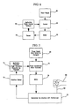
- the control for these two exemplary applications can be arranged as conceptually described below and illustrated in block diagram form in Figures 6 and 7 .
- a motor 60 consistent with the invention may include a component that is actuated by a user or machine.
- the motor 60 may control the position of a mirror, a control surface, (such as the tail of a dart or aircraft), or a robotic surgical device.
- the position of the component may be sensed by potentiometers, for example, and output to a control application 62 for causing real time control of the apparatus.
- the application may cause corresponding modification of an aircraft pitch and/or roll based on the motor position.
- the modified position of the apparatus may be sensed by a sensor 64, processed by the controlling application 62 and provided to a feedback control 66 for providing control of the motor 60 in dependence of the new position.
- Power supply 68 provides power to the entire system.
- FIG. 7 there is shown a control scheme for use of a motor 78 consistent with the invention in a simulator or generalized application including actual control of a device, vehicle, or aircraft.
- an interface sensor 72 which may include, for example, potentiometers for sensing the position of the handle 20 of a control stick with respect to the x- and y-axes.
- the position sensed by sensor 72 is provided as an input to an application controller 74.
- the application controller may, for example, be a flight simulation computer running software for a simulation program.
- the output of the controller 74 is provided to a power conditioner/motor controller 76 which provides an output to a motor 78 consistent with the invention to energize the motor coils and provide an output force to the user 80 through the joystick handle 82 in the manner described above.
- the power supply 84 provides power to the entire system.
- FIG. 8 an additional embodiment not belonging to the invention is illustrated in which a third degree of freedom is provided.
- this embodiment is substantially similar to the embodiment illustrated in Figures 2-4 , with the additional provision of a third lamination stack 41 with a third set of coils 43 for controlling twist/rotation of the shaft 22 of the handle 20 (not shown) about its center of rotation.
- the third lamination stack 41 may have a spherical or pseudo-spherical inner surface with parallel vertical slots 45.
- the third lamination stack 41 comprises a plurality of laminations, preferably identical, all stacked flat against each other (parallel to each other), and the laminations near the edge of the stack are disposed slightly closer to the shaft 22 of the handle 20 to form a stepped.concave surface about the rotational axis of the output shaft 22.
- Torque control can be established for the rotational axis by selecting and providing a given polarity/direction and magnitude of current through the third set of coils 43.
- Appropriate circuitry (not shown) is thus provided for selectively energizing the third set of coils 43, thereby causing the shaft 22 of the handle 20 to rotate.
- an elongated housing may be provided to accommodate the third lamination stack 41.
- a motor assembly that is capable of providing output in two or more degrees of freedom.
- the motor is simple and efficient in design and can be adapted for a variety of applications including joystick applications.
- the direct drive configuration eliminates the requirement for a transmission subsystem.
- a control handle or joystick can easily be disposed in a corner of the housing, rather than in its center, which may be advantageous in certain applications.
- the small minimum grip height of the handle or joystick is suitable when the assembly is used in physically small spaces and/or is disposed at both the left- and right-hand sides of a user.
- the two-arm rocker design provides low effective rotor inertia. Three degrees of freedom may be provided with only a slight elongation of the housing.
- the coil winding technique eliminates the need for coil commutation, thus saving both space and cost of materials.
- the elimination of several elements required in the prior art e.g., the reduction in the number of control circuits, lamination stacks, and coils required) permits a compact packaging for a motor assembly consistent with the invention.
- the motor assembly provides the input characteristics of an ordinary DC motor, without any of the disadvantages of a DC motor.
Claims (5)
- Moteur à plusieurs degrés de liberté, comportant :un arbre de sortie (22) ;un stator présentant un premier et un deuxième empilage de tôles (25, 27), chaque empilage de tôles (25, 27) présentant une surface intérieure courbe et une bobine (16, 18) enroulée sur celle-ci, les empilages de tôles (25, 27) étant agencés adjacents à l'arbre de sortie (22), etun rotor qui est fixé à l'arbre de sortie (22) et est monté mobile adjacent au stator avec un entrefer ménagé entre le rotor et le stator, le rotor comportant au moins un aimant (40, 42) qui est disposé sur celui-ci et qui est mobile le long de la surface intérieure courbe des empilages de tôles (25, 27) dans des directions qui définissent au moins un premier et un deuxième degré de liberté,dans lequel l'excitation de la bobine (16) du premier empilage de tôles (25) établit un premier champ magnétique pour solliciter l'arbre de sortie (22) en rotation dans un premier plan, et dans lequel l'excitation de la bobine (18) du deuxième empilage de tôles (27) établit un deuxième champ magnétique pour solliciter l'arbre de sortie (22) en rotation dans un deuxième plan orthogonal au premier plan,caractérisé en ce que
le stator présente seulement deux empilages de tôles (25, 27) avec seulement deux bobines respectives (16, 18), les empilages de tôles (25, 27) étant agencés autour de l'arbre de sortie (22) de manière à être perpendiculaire l'un par rapport à l'autre, et les tôles du premier empilage de tôles (25) et du deuxième empilage de tôles (27) étant parallèles les unes aux autres. - Moteur selon la revendication 1, dans lequel le premier degré de liberté est perpendiculaire à l'axe longitudinal de fils de la bobine (16) associée au premier degré de liberté, et le deuxième degré de liberté est perpendiculaire à l'axe longitudinal de fils de l'autre bobine (18).
- Moteur selon la revendication 1 ou 2, dans lequel les premier et deuxième empilages de tôles (25, 27) présentent chacun une pluralité de tôles empilées à plat les unes contre les autres et de manière parallèle les unes aux autres, et dans lequel les tôles à proximité du bord de l'empilage (25, 27) sont disposées légèrement plus près de l'arbre de sortie (22) pour former une surface concave étagée autour de l'axe longitudinal de l'arbre de sortie (22) dans un plan orthogonal à une face latérale de la pluralité de tôles.
- Moteur selon la revendication 3, dans lequel une forme de la surface concave étagée de la pluralité de tôles autour d'un équateur de la pluralité de tôles correspond approximativement à un arc avec un rayon constant dans un plan orthogonal à une face latérale de la pluralité de tôles.
- Moteur selon la revendication 3 ou 4, dans lequel les empilages de tôles (25, 27) présentent plusieurs fentes (S) réalisées dans ceux-ci.
Applications Claiming Priority (3)
| Application Number | Priority Date | Filing Date | Title |
|---|---|---|---|
| US40154902P | 2002-08-06 | 2002-08-06 | |
| US401549P | 2002-08-06 | ||
| PCT/US2003/024536 WO2004013803A2 (fr) | 2002-08-06 | 2003-08-06 | Dispositif de commande a entrainement direct avec retroaction haptique |
Publications (2)
| Publication Number | Publication Date |
|---|---|
| EP1529256A2 EP1529256A2 (fr) | 2005-05-11 |
| EP1529256B1 true EP1529256B1 (fr) | 2010-10-06 |
Family
ID=31495975
Family Applications (1)
| Application Number | Title | Priority Date | Filing Date |
|---|---|---|---|
| EP03767227A Expired - Lifetime EP1529256B1 (fr) | 2002-08-06 | 2003-08-06 | Dispositif de commande a entrainement direct avec retroaction haptique |
Country Status (7)
| Country | Link |
|---|---|
| US (2) | US7394173B2 (fr) |
| EP (1) | EP1529256B1 (fr) |
| AT (1) | ATE484017T1 (fr) |
| AU (1) | AU2003258087A1 (fr) |
| CA (1) | CA2533552C (fr) |
| DE (1) | DE60334458D1 (fr) |
| WO (1) | WO2004013803A2 (fr) |
Families Citing this family (22)
| Publication number | Priority date | Publication date | Assignee | Title |
|---|---|---|---|---|
| DE102006002634B4 (de) * | 2005-07-19 | 2009-11-26 | Preh Gmbh | Bedienelement mit Kipphaptik |
| US7759894B2 (en) * | 2006-10-26 | 2010-07-20 | Honeywell International Inc. | Cogless motor driven active user interface haptic feedback system |
| US7750593B2 (en) * | 2006-10-26 | 2010-07-06 | Honeywell International Inc. | Active human-machine interface system without a force sensor |
| US8090481B2 (en) * | 2007-02-20 | 2012-01-03 | Raytheon Company | Manual human interfaces to electronics |
| US7761254B2 (en) * | 2007-05-11 | 2010-07-20 | Caterpillar Inc | Operator interface assembly including a Hall effect element and machine using same |
| DE102008004909B4 (de) * | 2008-01-18 | 2010-09-09 | Preh Gmbh | Bedienelement mit verbesserter Kipphaptik |
| FR2940846B1 (fr) * | 2009-01-05 | 2011-03-18 | Guillemot Corp | Dispositif permettant la detection du mouvement d'un manche par effet hall, procede de fabrication et manette correspondants |
| US9870021B2 (en) * | 2009-04-15 | 2018-01-16 | SeeScan, Inc. | Magnetic manual user interface devices |
| FR2954835B1 (fr) * | 2009-12-30 | 2012-04-13 | Ratier Figeac Soc | Dispositif de pilotage de vehicule a actionneur electromagnetique |
| US10103600B2 (en) * | 2010-01-20 | 2018-10-16 | Patrick J. Dugas | Flywheel |
| CN101976522B (zh) * | 2010-09-26 | 2013-05-01 | 北京航空航天大学 | 飞机驾驶盘力反馈系统 |
| US8809824B1 (en) | 2010-12-13 | 2014-08-19 | The Boeing Company | Cryogenically cooled radiation shield device and associated method |
| US8723820B1 (en) | 2011-02-16 | 2014-05-13 | Google Inc. | Methods and apparatus related to a haptic feedback drawing device |
| EP2935000B1 (fr) * | 2012-12-20 | 2019-06-26 | BAE Systems PLC | Appareil initiateur |
| WO2017053878A1 (fr) * | 2015-09-25 | 2017-03-30 | Oculus Vr, Llc | Surface haptique avec appareil d'amortissement |
| US11009892B2 (en) | 2019-03-19 | 2021-05-18 | Honeywell International Inc. | Active human-machine user interface feedback system with spherical motor |
| FR3095804B1 (fr) * | 2019-05-06 | 2021-09-24 | Safran Electronics & Defense | Dispositif d’application d’effort pour manche de pilotage |
| FR3108741A1 (fr) * | 2020-03-31 | 2021-10-01 | Moving Magnet Technologies | Dispositif haptique passif |
| US11260297B2 (en) | 2020-05-01 | 2022-03-01 | Dell Products L.P. | Information handling system wheel input device |
| US11439902B2 (en) | 2020-05-01 | 2022-09-13 | Dell Products L.P. | Information handling system gaming controls |
| US11433314B2 (en) | 2020-05-01 | 2022-09-06 | Dell Products L.P. | Information handling system hands free voice and text chat |
| FR3128072B1 (fr) * | 2021-10-07 | 2024-03-08 | Safran Electronics & Defense | Machine électrique tournante, mini manche à retour d’effort et aéronef associés |
Citations (1)
| Publication number | Priority date | Publication date | Assignee | Title |
|---|---|---|---|---|
| EP0113267A1 (fr) * | 1982-12-07 | 1984-07-11 | ETAT-FRANCAIS représenté par le Délégué Général pour l' Armement | Convertisseur électromécanique à plusieurs degrés de liberté |
Family Cites Families (33)
| Publication number | Priority date | Publication date | Assignee | Title |
|---|---|---|---|---|
| GB1553076A (en) * | 1975-06-02 | 1979-09-19 | Dupont Research & Investment S | Electric motor |
| US4260035A (en) | 1979-07-26 | 1981-04-07 | The Johns Hopkins University | Chin controller system for powered wheelchair |
| US4507639A (en) | 1979-12-26 | 1985-03-26 | Texas Instruments Incorporated | Inductive position sensor |
| US4401986A (en) | 1979-12-26 | 1983-08-30 | Texas Instruments Incorporated | Position sensor and system |
| US4584577A (en) | 1982-10-20 | 1986-04-22 | Brookes & Gatehouse Limited | Angular position sensor |
| US4764698A (en) * | 1983-01-26 | 1988-08-16 | Tohoku Metal Industries, Ltd. | A.C. electric motors having a stator forming orthogonal magnetic paths |
| US4733214A (en) | 1983-05-23 | 1988-03-22 | Andresen Herman J | Multi-directional controller having resiliently biased cam and cam follower for tactile feedback |
| US4639667A (en) | 1983-05-23 | 1987-01-27 | Andresen Herman J | Contactless controllers sensing displacement along two orthogonal directions by the overlap of a magnet and saturable cores |
| JPH0756607B2 (ja) * | 1984-03-02 | 1995-06-14 | 株式会社日本自動車部品総合研究所 | 多方向駆動形電磁式位置制御装置 |
| US4719381A (en) * | 1985-08-21 | 1988-01-12 | The Curators Of The University Of Missouri | Electrical machines and apparatus for rotation around multiple axes |
| US4651130A (en) | 1985-08-28 | 1987-03-17 | United Technologies Corporation | Apparatus and method for retaining phase information for use with a multiple-coil inductive displacement sensor |
| US4739241A (en) * | 1986-10-09 | 1988-04-19 | Georgia Tech Research Corporation | Spherical motor particularly adapted for robotics |
| FR2612266B1 (fr) * | 1987-03-13 | 1989-07-13 | Aerospatiale | Palier magnetique pour le centrage actif, selon au moins un axe, d'un corps mobile selon un autre corps |
| US4908558A (en) * | 1988-04-22 | 1990-03-13 | Contraves Goerz Corporation | Spherical motion simulator |
| US4983869A (en) * | 1989-08-08 | 1991-01-08 | Sundstrand Corporation | Magnetic bearing |
| US5146566A (en) * | 1991-05-29 | 1992-09-08 | Ibm Corporation | Input/output system for computer user interface using magnetic levitation |
| DE69209187T2 (de) * | 1991-07-31 | 1996-08-14 | Mitsubishi Heavy Ind Ltd | Elektrischer Motor mit einem sphärischen Läufer und seine Anwendungsvorrichtung |
| FR2688105B1 (fr) * | 1992-02-28 | 1994-05-06 | Moving Magnet Technologies Sa | Actionneur rotatif electromagnetique monophase de course entre 60 et 120 degres. |
| US5280225A (en) * | 1992-04-20 | 1994-01-18 | Motorola, Inc. | Method and apparatus for multi-axis rotational motion |
| US5319577A (en) * | 1992-12-18 | 1994-06-07 | Georgia Tech Research Corporation | Orientation sensing system and method for a spherical body |
| US5421694A (en) * | 1993-05-20 | 1995-06-06 | Caterpillar Inc. | Non-contacting joystick |
| US5805140A (en) | 1993-07-16 | 1998-09-08 | Immersion Corporation | High bandwidth force feedback interface using voice coils and flexures |
| DE19501439A1 (de) | 1995-01-19 | 1996-09-05 | Meins Juergen Prof Dr Ing | Elektromechanische Bedienungseinrichtung |
| JPH08242572A (ja) * | 1995-02-28 | 1996-09-17 | Japan Servo Co Ltd | 3相永久磁石式回転電機 |
| US5687080A (en) * | 1995-06-20 | 1997-11-11 | Ziba Design, Inc. | Multiple axis data input apparatus and method |
| US5754023A (en) * | 1995-10-26 | 1998-05-19 | Cybernet Systems Corporation | Gyro-stabilized platforms for force-feedback applications |
| FR2764748B1 (fr) * | 1997-06-13 | 1999-10-01 | Claude Oudet | Dispositif d'entrainement electromagnetique a aimant permanent mobile |
| DE19806611C2 (de) * | 1998-02-18 | 2002-11-21 | Deutsch Zentr Luft & Raumfahrt | Elektromechanische Bedieneinrichtung |
| USH2017H1 (en) * | 1998-04-02 | 2002-04-02 | The United States Of America As Represented By The Secretary Of The Air Force | Virtual reality force emulation |
| GB9823159D0 (en) | 1998-10-22 | 1998-12-16 | Gill Michael J | Control apparatus |
| US6320284B1 (en) | 1998-12-23 | 2001-11-20 | Engineering Matters, Inc. | Motor assembly allowing output in multiple degrees of freedom |
| US6664666B2 (en) * | 1998-12-23 | 2003-12-16 | Engineering Matters, Inc. | Motor assembly allowing output in multiple degrees of freedom |
| US7061466B1 (en) * | 1999-05-07 | 2006-06-13 | Immersion Corporation | Force feedback device including single-phase, fixed-coil actuators |
-
2003
- 2003-08-06 WO PCT/US2003/024536 patent/WO2004013803A2/fr not_active Application Discontinuation
- 2003-08-06 US US10/635,318 patent/US7394173B2/en active Active
- 2003-08-06 AU AU2003258087A patent/AU2003258087A1/en not_active Abandoned
- 2003-08-06 AT AT03767227T patent/ATE484017T1/de not_active IP Right Cessation
- 2003-08-06 EP EP03767227A patent/EP1529256B1/fr not_active Expired - Lifetime
- 2003-08-06 DE DE60334458T patent/DE60334458D1/de not_active Expired - Lifetime
- 2003-08-06 CA CA2533552A patent/CA2533552C/fr not_active Expired - Lifetime
-
2008
- 2008-06-27 US US12/163,805 patent/US20080284257A1/en not_active Abandoned
Patent Citations (1)
| Publication number | Priority date | Publication date | Assignee | Title |
|---|---|---|---|---|
| EP0113267A1 (fr) * | 1982-12-07 | 1984-07-11 | ETAT-FRANCAIS représenté par le Délégué Général pour l' Armement | Convertisseur électromécanique à plusieurs degrés de liberté |
Also Published As
| Publication number | Publication date |
|---|---|
| CA2533552A1 (fr) | 2004-02-12 |
| CA2533552C (fr) | 2012-07-17 |
| ATE484017T1 (de) | 2010-10-15 |
| AU2003258087A8 (en) | 2004-02-23 |
| US20080284257A1 (en) | 2008-11-20 |
| WO2004013803A2 (fr) | 2004-02-12 |
| AU2003258087A1 (en) | 2004-02-23 |
| US7394173B2 (en) | 2008-07-01 |
| US20040027332A1 (en) | 2004-02-12 |
| DE60334458D1 (de) | 2010-11-18 |
| WO2004013803A3 (fr) | 2004-12-09 |
| EP1529256A2 (fr) | 2005-05-11 |
Similar Documents
| Publication | Publication Date | Title |
|---|---|---|
| US20080284257A1 (en) | Direct drive controller with haptic feedback | |
| CA2460142C (fr) | Ensemble moteur a multiples degres de liberte de sortie | |
| US6704001B1 (en) | Force feedback device including actuator with moving magnet | |
| US6320284B1 (en) | Motor assembly allowing output in multiple degrees of freedom | |
| US6982700B2 (en) | Method and apparatus for controlling force feedback interface systems utilizing a host computer | |
| CA2278726C (fr) | Procede et appareil incluant un actionneur perfectionne procurant un retour d'effort bande large et realiste | |
| EP0870296B1 (fr) | Appareil permettant d'obtenir une force retroactive et un systeme entree/sortie mecanique d'un faible cout pour des systemes informatiques | |
| US7061466B1 (en) | Force feedback device including single-phase, fixed-coil actuators | |
| US6437770B1 (en) | Flat-coil actuator having coil embedded in linkage | |
| US6339420B2 (en) | Actuation device having multiple degrees of freedom of movement and reduced inertia | |
| EP1046151B1 (fr) | Dispositif a retroaction de force comprenant un actionneur a aimant mobile | |
| US7728463B2 (en) | Reluctance laminations for a motor assembly | |
| GB2387218A (en) | A force feedback input device with mechanical stops adjacent to actuator minimum reluctance positions |
Legal Events
| Date | Code | Title | Description |
|---|---|---|---|
| PUAI | Public reference made under article 153(3) epc to a published international application that has entered the european phase |
Free format text: ORIGINAL CODE: 0009012 |
|
| 17P | Request for examination filed |
Effective date: 20050304 |
|
| AK | Designated contracting states |
Kind code of ref document: A2 Designated state(s): AT BE BG CH CY CZ DE DK EE ES FI FR GB GR HU IE IT LI LU MC NL PT RO SE SI SK TR |
|
| AX | Request for extension of the european patent |
Extension state: AL LT LV MK |
|
| DAX | Request for extension of the european patent (deleted) | ||
| 17Q | First examination report despatched |
Effective date: 20061218 |
|
| GRAP | Despatch of communication of intention to grant a patent |
Free format text: ORIGINAL CODE: EPIDOSNIGR1 |
|
| RAP1 | Party data changed (applicant data changed or rights of an application transferred) |
Owner name: ROCKWELL COLLINS, INC. |
|
| GRAS | Grant fee paid |
Free format text: ORIGINAL CODE: EPIDOSNIGR3 |
|
| GRAA | (expected) grant |
Free format text: ORIGINAL CODE: 0009210 |
|
| AK | Designated contracting states |
Kind code of ref document: B1 Designated state(s): AT BE BG CH CY CZ DE DK EE ES FI FR GB GR HU IE IT LI LU MC NL PT RO SE SI SK TR |
|
| REG | Reference to a national code |
Ref country code: GB Ref legal event code: FG4D |
|
| REG | Reference to a national code |
Ref country code: CH Ref legal event code: EP |
|
| REG | Reference to a national code |
Ref country code: IE Ref legal event code: FG4D |
|
| REF | Corresponds to: |
Ref document number: 60334458 Country of ref document: DE Date of ref document: 20101118 Kind code of ref document: P |
|
| REG | Reference to a national code |
Ref country code: NL Ref legal event code: VDEP Effective date: 20101006 |
|
| PG25 | Lapsed in a contracting state [announced via postgrant information from national office to epo] |
Ref country code: SI Free format text: LAPSE BECAUSE OF FAILURE TO SUBMIT A TRANSLATION OF THE DESCRIPTION OR TO PAY THE FEE WITHIN THE PRESCRIBED TIME-LIMIT Effective date: 20101006 |
|
| PG25 | Lapsed in a contracting state [announced via postgrant information from national office to epo] |
Ref country code: SE Free format text: LAPSE BECAUSE OF FAILURE TO SUBMIT A TRANSLATION OF THE DESCRIPTION OR TO PAY THE FEE WITHIN THE PRESCRIBED TIME-LIMIT Effective date: 20101006 Ref country code: FI Free format text: LAPSE BECAUSE OF FAILURE TO SUBMIT A TRANSLATION OF THE DESCRIPTION OR TO PAY THE FEE WITHIN THE PRESCRIBED TIME-LIMIT Effective date: 20101006 Ref country code: BG Free format text: LAPSE BECAUSE OF FAILURE TO SUBMIT A TRANSLATION OF THE DESCRIPTION OR TO PAY THE FEE WITHIN THE PRESCRIBED TIME-LIMIT Effective date: 20110106 Ref country code: PT Free format text: LAPSE BECAUSE OF FAILURE TO SUBMIT A TRANSLATION OF THE DESCRIPTION OR TO PAY THE FEE WITHIN THE PRESCRIBED TIME-LIMIT Effective date: 20110207 Ref country code: AT Free format text: LAPSE BECAUSE OF FAILURE TO SUBMIT A TRANSLATION OF THE DESCRIPTION OR TO PAY THE FEE WITHIN THE PRESCRIBED TIME-LIMIT Effective date: 20101006 Ref country code: NL Free format text: LAPSE BECAUSE OF FAILURE TO SUBMIT A TRANSLATION OF THE DESCRIPTION OR TO PAY THE FEE WITHIN THE PRESCRIBED TIME-LIMIT Effective date: 20101006 |
|
| PG25 | Lapsed in a contracting state [announced via postgrant information from national office to epo] |
Ref country code: GR Free format text: LAPSE BECAUSE OF FAILURE TO SUBMIT A TRANSLATION OF THE DESCRIPTION OR TO PAY THE FEE WITHIN THE PRESCRIBED TIME-LIMIT Effective date: 20110107 Ref country code: BE Free format text: LAPSE BECAUSE OF FAILURE TO SUBMIT A TRANSLATION OF THE DESCRIPTION OR TO PAY THE FEE WITHIN THE PRESCRIBED TIME-LIMIT Effective date: 20101006 |
|
| PG25 | Lapsed in a contracting state [announced via postgrant information from national office to epo] |
Ref country code: EE Free format text: LAPSE BECAUSE OF FAILURE TO SUBMIT A TRANSLATION OF THE DESCRIPTION OR TO PAY THE FEE WITHIN THE PRESCRIBED TIME-LIMIT Effective date: 20101006 Ref country code: CZ Free format text: LAPSE BECAUSE OF FAILURE TO SUBMIT A TRANSLATION OF THE DESCRIPTION OR TO PAY THE FEE WITHIN THE PRESCRIBED TIME-LIMIT Effective date: 20101006 Ref country code: ES Free format text: LAPSE BECAUSE OF FAILURE TO SUBMIT A TRANSLATION OF THE DESCRIPTION OR TO PAY THE FEE WITHIN THE PRESCRIBED TIME-LIMIT Effective date: 20110117 |
|
| PLBE | No opposition filed within time limit |
Free format text: ORIGINAL CODE: 0009261 |
|
| STAA | Information on the status of an ep patent application or granted ep patent |
Free format text: STATUS: NO OPPOSITION FILED WITHIN TIME LIMIT |
|
| PG25 | Lapsed in a contracting state [announced via postgrant information from national office to epo] |
Ref country code: DK Free format text: LAPSE BECAUSE OF FAILURE TO SUBMIT A TRANSLATION OF THE DESCRIPTION OR TO PAY THE FEE WITHIN THE PRESCRIBED TIME-LIMIT Effective date: 20101006 Ref country code: RO Free format text: LAPSE BECAUSE OF FAILURE TO SUBMIT A TRANSLATION OF THE DESCRIPTION OR TO PAY THE FEE WITHIN THE PRESCRIBED TIME-LIMIT Effective date: 20101006 Ref country code: SK Free format text: LAPSE BECAUSE OF FAILURE TO SUBMIT A TRANSLATION OF THE DESCRIPTION OR TO PAY THE FEE WITHIN THE PRESCRIBED TIME-LIMIT Effective date: 20101006 |
|
| 26N | No opposition filed |
Effective date: 20110707 |
|
| REG | Reference to a national code |
Ref country code: DE Ref legal event code: R097 Ref document number: 60334458 Country of ref document: DE Effective date: 20110707 |
|
| PG25 | Lapsed in a contracting state [announced via postgrant information from national office to epo] |
Ref country code: IT Free format text: LAPSE BECAUSE OF FAILURE TO SUBMIT A TRANSLATION OF THE DESCRIPTION OR TO PAY THE FEE WITHIN THE PRESCRIBED TIME-LIMIT Effective date: 20101006 |
|
| PG25 | Lapsed in a contracting state [announced via postgrant information from national office to epo] |
Ref country code: MC Free format text: LAPSE BECAUSE OF NON-PAYMENT OF DUE FEES Effective date: 20110831 |
|
| REG | Reference to a national code |
Ref country code: CH Ref legal event code: PL |
|
| PG25 | Lapsed in a contracting state [announced via postgrant information from national office to epo] |
Ref country code: LI Free format text: LAPSE BECAUSE OF NON-PAYMENT OF DUE FEES Effective date: 20110831 Ref country code: CH Free format text: LAPSE BECAUSE OF NON-PAYMENT OF DUE FEES Effective date: 20110831 |
|
| REG | Reference to a national code |
Ref country code: IE Ref legal event code: MM4A |
|
| PG25 | Lapsed in a contracting state [announced via postgrant information from national office to epo] |
Ref country code: IE Free format text: LAPSE BECAUSE OF NON-PAYMENT OF DUE FEES Effective date: 20110806 |
|
| PG25 | Lapsed in a contracting state [announced via postgrant information from national office to epo] |
Ref country code: CY Free format text: LAPSE BECAUSE OF EXPIRATION OF PROTECTION Effective date: 20101006 Ref country code: LU Free format text: LAPSE BECAUSE OF NON-PAYMENT OF DUE FEES Effective date: 20110806 |
|
| PG25 | Lapsed in a contracting state [announced via postgrant information from national office to epo] |
Ref country code: TR Free format text: LAPSE BECAUSE OF FAILURE TO SUBMIT A TRANSLATION OF THE DESCRIPTION OR TO PAY THE FEE WITHIN THE PRESCRIBED TIME-LIMIT Effective date: 20101006 |
|
| PG25 | Lapsed in a contracting state [announced via postgrant information from national office to epo] |
Ref country code: HU Free format text: LAPSE BECAUSE OF FAILURE TO SUBMIT A TRANSLATION OF THE DESCRIPTION OR TO PAY THE FEE WITHIN THE PRESCRIBED TIME-LIMIT Effective date: 20101006 |
|
| REG | Reference to a national code |
Ref country code: FR Ref legal event code: PLFP Year of fee payment: 14 |
|
| REG | Reference to a national code |
Ref country code: FR Ref legal event code: PLFP Year of fee payment: 15 |
|
| REG | Reference to a national code |
Ref country code: FR Ref legal event code: PLFP Year of fee payment: 16 |
|
| PGFP | Annual fee paid to national office [announced via postgrant information from national office to epo] |
Ref country code: GB Payment date: 20220721 Year of fee payment: 20 Ref country code: DE Payment date: 20220616 Year of fee payment: 20 |
|
| PGFP | Annual fee paid to national office [announced via postgrant information from national office to epo] |
Ref country code: FR Payment date: 20220721 Year of fee payment: 20 |
|
| REG | Reference to a national code |
Ref country code: DE Ref legal event code: R071 Ref document number: 60334458 Country of ref document: DE |
|
| REG | Reference to a national code |
Ref country code: GB Ref legal event code: PE20 Expiry date: 20230805 |
|
| PG25 | Lapsed in a contracting state [announced via postgrant information from national office to epo] |
Ref country code: GB Free format text: LAPSE BECAUSE OF EXPIRATION OF PROTECTION Effective date: 20230805 |