EP1529140B1 - Vorrichtung zur verankerung einer verkleidung an einer schlitzwand - Google Patents
Vorrichtung zur verankerung einer verkleidung an einer schlitzwand Download PDFInfo
- Publication number
- EP1529140B1 EP1529140B1 EP03758199A EP03758199A EP1529140B1 EP 1529140 B1 EP1529140 B1 EP 1529140B1 EP 03758199 A EP03758199 A EP 03758199A EP 03758199 A EP03758199 A EP 03758199A EP 1529140 B1 EP1529140 B1 EP 1529140B1
- Authority
- EP
- European Patent Office
- Prior art keywords
- spring
- panel
- diameter
- conical
- anchoring
- Prior art date
- Legal status (The legal status is an assumption and is not a legal conclusion. Google has not performed a legal analysis and makes no representation as to the accuracy of the status listed.)
- Expired - Lifetime
Links
- 238000004873 anchoring Methods 0.000 title claims abstract description 25
- 239000011490 mineral wool Substances 0.000 claims abstract description 3
- 230000000717 retained effect Effects 0.000 claims description 3
- 238000000465 moulding Methods 0.000 claims description 2
- 238000000034 method Methods 0.000 claims 1
- 230000002035 prolonged effect Effects 0.000 claims 1
- 238000005192 partition Methods 0.000 abstract 2
- 239000006260 foam Substances 0.000 abstract 1
- 239000000463 material Substances 0.000 abstract 1
- 238000009413 insulation Methods 0.000 description 9
- 238000009415 formwork Methods 0.000 description 8
- 230000002787 reinforcement Effects 0.000 description 4
- 239000011248 coating agent Substances 0.000 description 3
- 238000000576 coating method Methods 0.000 description 3
- 238000002955 isolation Methods 0.000 description 3
- 238000004519 manufacturing process Methods 0.000 description 3
- 238000003860 storage Methods 0.000 description 3
- 239000012778 molding material Substances 0.000 description 2
- 229910001335 Galvanized steel Inorganic materials 0.000 description 1
- 230000006835 compression Effects 0.000 description 1
- 238000007906 compression Methods 0.000 description 1
- 230000006866 deterioration Effects 0.000 description 1
- 238000010586 diagram Methods 0.000 description 1
- 238000009826 distribution Methods 0.000 description 1
- -1 for example Substances 0.000 description 1
- 239000008397 galvanized steel Substances 0.000 description 1
- 239000011521 glass Substances 0.000 description 1
- 239000002184 metal Substances 0.000 description 1
- 239000002984 plastic foam Substances 0.000 description 1
- 229920000642 polymer Polymers 0.000 description 1
- 238000004080 punching Methods 0.000 description 1
- 239000011435 rock Substances 0.000 description 1
- 229910001220 stainless steel Inorganic materials 0.000 description 1
Images
Classifications
-
- E—FIXED CONSTRUCTIONS
- E04—BUILDING
- E04B—GENERAL BUILDING CONSTRUCTIONS; WALLS, e.g. PARTITIONS; ROOFS; FLOORS; CEILINGS; INSULATION OR OTHER PROTECTION OF BUILDINGS
- E04B1/00—Constructions in general; Structures which are not restricted either to walls, e.g. partitions, or floors or ceilings or roofs
- E04B1/38—Connections for building structures in general
- E04B1/41—Connecting devices specially adapted for embedding in concrete or masonry
Definitions
- the present invention relates to a device for anchoring a coating on a molded wall such as, for example, a wall or a ceiling, a floor.
- stripping is done by removing the boards and their supporting structures.
- the insulation panels are then fixed to the slab via the anchoring means whose parts initially projecting are embedded in the molded slab.
- the various solutions that have been proposed so far for making the anchoring devices can be classified in two categories, namely: the anchoring means which are incorporated in the insulation panels during their manufacture and the means of anchorages intended to be assembled on site at the time of their use.
- the first solution makes it possible to offer a ready-to-use product at a more attractive price since it is manufactured in the factory using manufacturing means that ensure high production rates.
- it avoids having to organize for these fasteners a distribution circuit, separate from that of the panels.
- it suffers from a major disadvantage due to the fact that the panels equipped with projecting anchoring means become difficult to store and manipulate. This is why articulated anchoring devices have been proposed, which can be folded against the panels, during storage and transportation, and can take an extended position when using the panels. This is a more expensive and less effective solution because the stress due to articulation and tilting does not allow the use of forms best suited to obtain a good anchorage.
- anchoring devices are used in the form of helical springs that are partially screwed into the insulation panels, the part emerging from the formwork being used to anchor, A solution of this type is described in the European patent application EP 0 034 545 .
- the object of the invention is a solution that combines the advantages of the two previously mentioned solutions without understanding the disadvantages.
- a device for anchoring a coating on a molded wall comprising a helical spring comprising a first part which is part of a substantially cylindrical shape and which is intended to be screwed into the insulation panel, and a second portion for anchoring in the wall at the time of molding.
- this device is characterized in that the second part is in a substantially conical shape and extends the first part flaring.
- the conical shape of the protruding portion of the panel has a very thin (that of the wire used for the realization of the spring).
- the panels can be superimposed without loss of space.
- the stiffness of the spring is a function of the diameter of the turns, the force to compress the conical portion of the spring will be relatively low. It is the same with regard to the punching action of the spring on the panel which compresses it during an overlay.
- the risk of deterioration of this panel are minimal.
- Another advantage of this solution is that in a stack of panels, the highest panel of the stack is slightly raised by the action of the springs, the other panels remaining properly stacked. This slight elevation of the panel allows the handlers to pass their fingers under the panel and get good grips. The handling of the panels is thus considerably facilitated.
- the presence of the conical part of the spring facilitates the screwing of the device in the panels, whether it is a screwing on the site or a screwing factory: This conical part allows a better grip at the hand and better hold when using a screwdriver.
- the turn of the conical portion may have a greater diameter than that of the turns of the cylindrical portion, so that one obtains at this junction l equivalent of a shoulder.
- this shoulder will abut on the outer face of the panel by stopping the screwing. The operator will no longer have to worry about the depth of screwing.
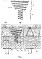
- the first turn of the second portion 3 has a substantially larger diameter than that of the first portion 2.
- the junction between the two parts is achieved through a length of wire 4 which extends radially (at the image of a shoulder).
- This spring 1 may advantageously be made of a galvanized or stainless steel wire or polymer.
- the panels P 1 , P 2 are laid flat on a horizontal formwork table TC mounted on a support structure here constituted by straight legs PS (partially shown).
- the springs 1 which constitute the fixing devices are screwed on the upper wall of the panels (here the panel P 1 ) so that only the second portion 3 (conical) is projecting with respect to said wall.
- the operator places the metal reinforcements AM (reinforcement) and proceeds to pour the floor PL, for example with concrete, until the desired level be reached.
- the operator can remove the formwork table TC and its support structure PS.
- the anchoring devices 1 can be screwed down at the factory or even on the site just before the panels P 1 , P 2 are installed.
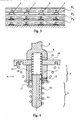
- the panels P 1 , P 2 , P 3 equipped with anchoring devices, can be easily stacked for storage and transport ( figure 3 ).
- Screwing anchoring devices described above can be done by hand or using a screwing device: Indeed, its shape lends itself perfectly to these two modes of screwing.
- the figure 4 shows a screwing bell 6 which can be mounted in the mandrel of a conventional screwdriver.
- This screwing bell 6 comprises a tubular body 7 open in its lower part and terminated in its upper part by a bottom 8 extended by a coaxial rod 9 adapted to engage in the mandrel of the screwdriver.
- the lower face of the disc comprises a coaxial annular groove (groove) 11 of diameter substantially equal to that of said turn.
- This cavity 11 comprises a protuberance intended to abut on the end of the spring so as to be able to drive it in rotation.
- This core 13 is biased by a spring 14 so as to naturally assume an extended position in which it emerges outside the body 7 over a length substantially equal to that of the cylindrical portion 2 of the spring, a position in which it is retained. thanks to a limit stop (here a needle screw 15 which engages in an axial groove 16 of the core 13).
- a limit stop here a needle screw 15 which engages in an axial groove 16 of the core 13.
- the distance between the bottom of the annular cavity 11 and the lower end of the body 7 is substantially equal to the height of the conical portion 3 of the spring.
- a radial notch 17 formed on the lower end of the body 7 allows the passage of the radial section 4 spring wire and its rotational drive.
- the spring is guided (in particular by the core 13) and rotated by the screwing bell.
- the lower end of the core 13 may have a conical shape.
Landscapes
- Engineering & Computer Science (AREA)
- Architecture (AREA)
- Physics & Mathematics (AREA)
- Electromagnetism (AREA)
- Civil Engineering (AREA)
- Structural Engineering (AREA)
- Forms Removed On Construction Sites Or Auxiliary Members Thereof (AREA)
- Soil Working Implements (AREA)
- Connection Or Junction Boxes (AREA)
- Joining Of Building Structures In Genera (AREA)
- Load-Bearing And Curtain Walls (AREA)
- Coating Apparatus (AREA)
- Vehicle Interior And Exterior Ornaments, Soundproofing, And Insulation (AREA)
- Automotive Seat Belt Assembly (AREA)
- Details Or Accessories Of Spraying Plant Or Apparatus (AREA)
Claims (11)
- Vorrichtung zur Verankerung einer Verkleidung (P1, P2) an einer Schlitzwand (PL), wobei diese Vorrichtung eine Spiralfeder, die einen ersten Teil (2) einschließt, der eine im Wesentlichen zylindrischen Form aufweist und der zum Einschrauben in die Verkleidung (P1, P2) bestimmt ist, und einen zweiten Teil (3), der zur Verankerung in der Wand (PL) während des Preßformens bestimmt ist, einschließt, dadurch gekennzeichnet, dass der zweite Teil eine im Wesentlichen konische Form aufweist und den ersten Teil (P2) unter konischer Erweiterung verlängert.
- Vorrichtung nach Anspruch 1,
dadurch gekennzeichnet, dass an der Verbindungsstelle zwischen den zwei Teilen der Feder der Schraubengang des konischen Teils einen Durchmesser aufweist, der größer ist als derjenige der Schraubengänge des zylindrischen Teils. - Vorrichtung nach Anspruch 2,
dadurch gekennzeichnet, dass die Verbindungsstelle zwischen den zwei Teilen (2, 3) durch ein Drahtstück (4), das sich radial ausdehnt, realisiert ist. - Vorrichtung nach einem der vorhergehenden Ansprüche,
dadurch gekennzeichnet, dass sie eine Schraubglocke (6) einschließt, die einen röhrenförmigen Körper (7) einschließt, der an seinem unteren Teil offen ist und in seinem oberen Teil in einem Boden (8) endet, der von einem koaxialen Schaft (9) verlängert wird, der dazu geeignet ist, in den Dorn des Schraubers einzugreifen, und eine koaxiale Scheibe (10), die mit dem Körper (7) aus einem Stück besteht, deren Durchmesser etwas größer ist als der Durchmesser der größten Windung der Feder, wobei die Unterseite dieser Scheibe (10) einen koaxialen ringförmige Hohlraum (11) einschließt, der mit einem Drehbewegungsanschlag für das Ende der Feder versehen ist. - Vorrichtung Anspruch 4,
dadurch gekennzeichnet, dass der Abstand zwischen dem Boden des ringförmigen Hohlraums (11) und dem unteren Ende des Körpers (7) im Wesentlichen gleich der Höhe des konischen Teils (3) der Feder ist. - Vorrichtung nach einem der Ansprüche 4 und 5,
dadurch gekennzeichnet, dass der zylindrische Hohlraum des Körpers (7) axial gleitend auf einem Kern (13) von im Wesentlichen einem Durchmesser entsprechend dem Innendurchmesser des zylindrischen Teils (2) der Feder montiert ist und dadurch, dass dieser Kern (13) durch eine Feder (14) belastet wird, derart, dass er eine ausgefahrene Position einnimmt, in der er auf eine Länge, die im Wesentlichen gleich derjenigen des zylindrischen Teils (2) der Feder ist, aus dem Körper (7) heraus ragt, ein Position, in der er auf Grund des Laufstopps (15) gehalten wird. - Vorrichtung nach einem der Ansprüche 4 bis 6,
dadurch gekennzeichnet, dass das untere Ende des Körper (7) eine radiale Kerbe (17) einschließt, die den Durchgang des oben genannten radialen Drahtstückes (4) ermöglicht. - Isolierpaneel, insbesondere aus Mineralwolle,
dadurch gekennzeichnet, dass es Verankerungsvorrichtungen nach einem der vorhergehenden Ansprüche, die teilweise in das Paneel (P1, P2) geschraubt sind, einschließt. - Paneel nach Anspruch 8,
dadurch gekennzeichnet, dass die Verankerungsvorrichtungen so geschraubt sind, dass nur ihr zweiter Teil (3) bezüglich der Außenfläche des Paneels (P1, P2) heraus ragt. - Paneel nach Anspruch 9,
dadurch gekennzeichnet, dass das Gewicht des Paneels so ist, dass, wenn mehrere Paneele gestapelt werden, die konischen Teile (3) der Verankerungsvorrichtungen komprimiert werden, um eine Höhe aufzuweisen, die gleich dem Durchmesser des Drahts der Feder ist, wobei nur das auf dem Stapel obenauf liegende Paneel (P1) etwas absteht ist und den Durchgang der Finger unter diesem Paneel ermöglicht. - Verfahren zur Herstellung eines Paneels nach einem der Ansprüche 8 bis 10, wobei die Verankerungsvorrichtungen eingeschraubt werden, bis eine zwischen den zwei Teilen (2, 3) ausgebildete Schulter auf der Außenfläche des Paneels aufstößt.
Applications Claiming Priority (3)
| Application Number | Priority Date | Filing Date | Title |
|---|---|---|---|
| FR0210233 | 2002-08-08 | ||
| FR0210233A FR2843413B1 (fr) | 2002-08-08 | 2002-08-08 | Dispositif pour l'ancrage d'un revetement sur une paroi moulee |
| PCT/FR2003/002452 WO2004016871A2 (fr) | 2002-08-08 | 2003-08-01 | Dispositif pour l'ancrage d'un revetement sur une paroi moulee |
Publications (2)
| Publication Number | Publication Date |
|---|---|
| EP1529140A2 EP1529140A2 (de) | 2005-05-11 |
| EP1529140B1 true EP1529140B1 (de) | 2009-04-29 |
Family
ID=30471087
Family Applications (1)
| Application Number | Title | Priority Date | Filing Date |
|---|---|---|---|
| EP03758199A Expired - Lifetime EP1529140B1 (de) | 2002-08-08 | 2003-08-01 | Vorrichtung zur verankerung einer verkleidung an einer schlitzwand |
Country Status (6)
| Country | Link |
|---|---|
| EP (1) | EP1529140B1 (de) |
| AT (1) | ATE430227T1 (de) |
| AU (1) | AU2003274216A1 (de) |
| DE (1) | DE60327437D1 (de) |
| FR (1) | FR2843413B1 (de) |
| WO (1) | WO2004016871A2 (de) |
Families Citing this family (2)
| Publication number | Priority date | Publication date | Assignee | Title |
|---|---|---|---|---|
| DE102010050122A1 (de) * | 2010-11-03 | 2012-05-03 | Holger Rupprecht | Armierter Betonstopfen und Verfahren zur Herstellung eines Beton-Holz-Verbundelements |
| FR3132816A1 (fr) * | 2022-02-22 | 2023-08-25 | Aristide Boisseau Pierre | Dispositif Extracteur d’un Objet Solide Implanté dans un Substrat Solide et Procédé d’Extraction |
Family Cites Families (4)
| Publication number | Priority date | Publication date | Assignee | Title |
|---|---|---|---|---|
| FR2054713A5 (de) * | 1969-07-24 | 1971-05-07 | Avendano Alfredo | |
| FR2476177B1 (fr) * | 1980-02-18 | 1987-06-19 | Paul Dominique | Dispositif de fixation de panneaux de parement lors de la realisation de parois de beton et outil a main pour la mise en oeuvre de ce dispositif |
| FR2528751A1 (fr) * | 1982-06-21 | 1983-12-23 | Saint Gobain Isover | Pose d'attaches helicoidales dans des panneaux legers |
| FR2586053B1 (fr) * | 1985-08-08 | 1987-10-30 | Cuguen Joel | Dispositif de fixation sous plancher beton, de panneaux isolants utilises en fond de coffrage, et outil de pose du dispositif |
-
2002
- 2002-08-08 FR FR0210233A patent/FR2843413B1/fr not_active Expired - Fee Related
-
2003
- 2003-08-01 AT AT03758199T patent/ATE430227T1/de active
- 2003-08-01 DE DE60327437T patent/DE60327437D1/de not_active Expired - Lifetime
- 2003-08-01 WO PCT/FR2003/002452 patent/WO2004016871A2/fr not_active Ceased
- 2003-08-01 AU AU2003274216A patent/AU2003274216A1/en not_active Abandoned
- 2003-08-01 EP EP03758199A patent/EP1529140B1/de not_active Expired - Lifetime
Also Published As
| Publication number | Publication date |
|---|---|
| FR2843413A1 (fr) | 2004-02-13 |
| WO2004016871A3 (fr) | 2004-04-08 |
| EP1529140A2 (de) | 2005-05-11 |
| AU2003274216A1 (en) | 2004-03-03 |
| DE60327437D1 (de) | 2009-06-10 |
| WO2004016871A2 (fr) | 2004-02-26 |
| FR2843413B1 (fr) | 2006-01-13 |
| AU2003274216A8 (en) | 2004-03-03 |
| ATE430227T1 (de) | 2009-05-15 |
Similar Documents
| Publication | Publication Date | Title |
|---|---|---|
| EP2439352B1 (de) | Mauer mit verlorener Schalung und Verbindungsleine | |
| EP2495375B1 (de) | Integrierte wandschalung mit einem mobilen schwenkbarem verbindungselement | |
| EP1529140B1 (de) | Vorrichtung zur verankerung einer verkleidung an einer schlitzwand | |
| EP2792806B1 (de) | Vorgefertigte platte mit unterbrochener wärmebrücke, ihr herstellungsverfahren und baumethode einer decke mit einer solchen platte | |
| EP2580827B1 (de) | Vorrichtung, kit und verfahren zur verankerung eines elements an einer aussenfläche oder wand eines gebäudes | |
| FR2543481A1 (fr) | Dispositif d'ancrage dans le beton | |
| EP0070770A1 (de) | Vorrichtung zur Auflage eines Fussbodens auf einer Mauer und Konstruktionsverfahren hierfür | |
| EP1956156B1 (de) | Anschluss zur Verbindung von zwei Platten einer Mauer mit verlorener Verschalung | |
| FR2927105A1 (fr) | Mur a coffrage perdu comportant un moyen de raccordement a un engin de manutention | |
| EP0034545A2 (de) | Verbindungsvorrichtung für Verkleidungsplatten während des Baus von Betonwänden und Handwerkszeug für die Verwendung dieser Vorrichtung | |
| EP2123845B1 (de) | Befestigungsvorrichtung von Sicherheits- und Arbeitskabeln auf Teleskopsäulen von Hubzeug für Decken- und Mauerpaneele | |
| EP2412888A2 (de) | Verbindungsanschluss einer Isolierplatte und mindestens einer Wand einer Mauer mit integrierter Dämmung, mit einem solchen Anschluss ausgestattetes Bauelement und mit einem solchen Bauelement ausgestattete Mauer | |
| EP3697981A1 (de) | Werkzeug zur in-situ-herstellung einer sandwichwand und verfahren zur anwendung davon | |
| FR2978467A1 (fr) | Panneau de mur comprenant une peau de beton interieure et une peau de beton exterieure | |
| FR2624154A1 (fr) | Dispositif de fixation de panneaux en materiau isolant a une dalle en beton arme | |
| BE1026893B1 (fr) | Crochet de maçonnerie arrondi | |
| EP3822427B1 (de) | Abstandshalterzubehör für die aufdoppelung einer wand | |
| FR2972208A1 (fr) | Mur a coffrage integre avec element mobile de liaison pivotant. | |
| FR2738581A1 (fr) | Coffrage perdu pour la realisation de parois porteuses isolantes thermiquement et/ou phonetiquement et parois ainsi obtenues | |
| FR2932248A1 (fr) | Outil et procede de deblocage du systeme de blocage du cable du support d'un dispositif de connexion pour luminaire au plafond | |
| FR2688102A1 (fr) | Dispositif elastique de maintien de boitiers d'appareillage electrique entre des banches. | |
| CH660618A5 (en) | Device for guiding tubes and/or pipes coming out of concrete slabs and its use | |
| EP4671461A1 (de) | Fortschrittliches mechanisches verbindungssystem für gemischte bodenbeläge, das eine schnelle montage und demontage des gemischten bodens und die wiederverwendung seiner komponenten ermöglicht, sowie entsprechender gemischter boden | |
| WO2008139084A2 (fr) | Barre de maintien de charge pour vehicule utilitaire et ensemble de barres pour maintien de charge | |
| FR2910916A1 (fr) | Mur a coffrage integre comportant un moyen provisoire de mise en place d'un moyen de raccordement du mur a un dispositif de levage |
Legal Events
| Date | Code | Title | Description |
|---|---|---|---|
| PUAI | Public reference made under article 153(3) epc to a published international application that has entered the european phase |
Free format text: ORIGINAL CODE: 0009012 |
|
| 17P | Request for examination filed |
Effective date: 20050304 |
|
| AK | Designated contracting states |
Kind code of ref document: A2 Designated state(s): AT BE BG CH CY CZ DE DK EE ES FI FR GB GR HU IE IT LI LU MC NL PT RO SE SI SK TR |
|
| AX | Request for extension of the european patent |
Extension state: AL LT LV MK |
|
| DAX | Request for extension of the european patent (deleted) | ||
| 17Q | First examination report despatched |
Effective date: 20070730 |
|
| GRAP | Despatch of communication of intention to grant a patent |
Free format text: ORIGINAL CODE: EPIDOSNIGR1 |
|
| RAP1 | Party data changed (applicant data changed or rights of an application transferred) |
Owner name: ROCKWOOL-ISOLATION S.A. Owner name: ATELIERS LR ETANCO |
|
| GRAS | Grant fee paid |
Free format text: ORIGINAL CODE: EPIDOSNIGR3 |
|
| GRAA | (expected) grant |
Free format text: ORIGINAL CODE: 0009210 |
|
| AK | Designated contracting states |
Kind code of ref document: B1 Designated state(s): AT BE BG CH CY CZ DE DK EE ES FI FR GB GR HU IE IT LI LU MC NL PT RO SE SI SK TR |
|
| REG | Reference to a national code |
Ref country code: GB Ref legal event code: FG4D Free format text: NOT ENGLISH |
|
| REG | Reference to a national code |
Ref country code: CH Ref legal event code: EP |
|
| REF | Corresponds to: |
Ref document number: 60327437 Country of ref document: DE Date of ref document: 20090610 Kind code of ref document: P |
|
| REG | Reference to a national code |
Ref country code: IE Ref legal event code: FG4D |
|
| RAP2 | Party data changed (patent owner data changed or rights of a patent transferred) |
Owner name: ROCKWOOL FRANCE S.A.S. Owner name: ATELIERS LR ETANCO |
|
| NLT2 | Nl: modifications (of names), taken from the european patent patent bulletin |
Owner name: ATELIERS LR ETANCO EN ROCKWOOL FRANCE S.A.S. Effective date: 20090819 |
|
| PG25 | Lapsed in a contracting state [announced via postgrant information from national office to epo] |
Ref country code: ES Free format text: LAPSE BECAUSE OF FAILURE TO SUBMIT A TRANSLATION OF THE DESCRIPTION OR TO PAY THE FEE WITHIN THE PRESCRIBED TIME-LIMIT Effective date: 20090809 Ref country code: FI Free format text: LAPSE BECAUSE OF FAILURE TO SUBMIT A TRANSLATION OF THE DESCRIPTION OR TO PAY THE FEE WITHIN THE PRESCRIBED TIME-LIMIT Effective date: 20090429 Ref country code: PT Free format text: LAPSE BECAUSE OF FAILURE TO SUBMIT A TRANSLATION OF THE DESCRIPTION OR TO PAY THE FEE WITHIN THE PRESCRIBED TIME-LIMIT Effective date: 20090829 |
|
| NLT1 | Nl: modifications of names registered in virtue of documents presented to the patent office pursuant to art. 16 a, paragraph 1 |
Owner name: ROCKWOOL FRANCE S.A.S. Owner name: ATELIERS LR ETANCO |
|
| PG25 | Lapsed in a contracting state [announced via postgrant information from national office to epo] |
Ref country code: SE Free format text: LAPSE BECAUSE OF FAILURE TO SUBMIT A TRANSLATION OF THE DESCRIPTION OR TO PAY THE FEE WITHIN THE PRESCRIBED TIME-LIMIT Effective date: 20090729 Ref country code: SI Free format text: LAPSE BECAUSE OF FAILURE TO SUBMIT A TRANSLATION OF THE DESCRIPTION OR TO PAY THE FEE WITHIN THE PRESCRIBED TIME-LIMIT Effective date: 20090429 |
|
| REG | Reference to a national code |
Ref country code: IE Ref legal event code: FD4D |
|
| PG25 | Lapsed in a contracting state [announced via postgrant information from national office to epo] |
Ref country code: RO Free format text: LAPSE BECAUSE OF FAILURE TO SUBMIT A TRANSLATION OF THE DESCRIPTION OR TO PAY THE FEE WITHIN THE PRESCRIBED TIME-LIMIT Effective date: 20090429 Ref country code: IE Free format text: LAPSE BECAUSE OF FAILURE TO SUBMIT A TRANSLATION OF THE DESCRIPTION OR TO PAY THE FEE WITHIN THE PRESCRIBED TIME-LIMIT Effective date: 20090429 Ref country code: EE Free format text: LAPSE BECAUSE OF FAILURE TO SUBMIT A TRANSLATION OF THE DESCRIPTION OR TO PAY THE FEE WITHIN THE PRESCRIBED TIME-LIMIT Effective date: 20090429 Ref country code: DK Free format text: LAPSE BECAUSE OF FAILURE TO SUBMIT A TRANSLATION OF THE DESCRIPTION OR TO PAY THE FEE WITHIN THE PRESCRIBED TIME-LIMIT Effective date: 20090429 Ref country code: CZ Free format text: LAPSE BECAUSE OF FAILURE TO SUBMIT A TRANSLATION OF THE DESCRIPTION OR TO PAY THE FEE WITHIN THE PRESCRIBED TIME-LIMIT Effective date: 20090429 |
|
| PG25 | Lapsed in a contracting state [announced via postgrant information from national office to epo] |
Ref country code: SK Free format text: LAPSE BECAUSE OF FAILURE TO SUBMIT A TRANSLATION OF THE DESCRIPTION OR TO PAY THE FEE WITHIN THE PRESCRIBED TIME-LIMIT Effective date: 20090429 |
|
| PLBE | No opposition filed within time limit |
Free format text: ORIGINAL CODE: 0009261 |
|
| STAA | Information on the status of an ep patent application or granted ep patent |
Free format text: STATUS: NO OPPOSITION FILED WITHIN TIME LIMIT |
|
| PG25 | Lapsed in a contracting state [announced via postgrant information from national office to epo] |
Ref country code: MC Free format text: LAPSE BECAUSE OF NON-PAYMENT OF DUE FEES Effective date: 20090831 Ref country code: BG Free format text: LAPSE BECAUSE OF FAILURE TO SUBMIT A TRANSLATION OF THE DESCRIPTION OR TO PAY THE FEE WITHIN THE PRESCRIBED TIME-LIMIT Effective date: 20090729 |
|
| REG | Reference to a national code |
Ref country code: CH Ref legal event code: PL |
|
| 26N | No opposition filed |
Effective date: 20100201 |
|
| GBPC | Gb: european patent ceased through non-payment of renewal fee |
Effective date: 20090801 |
|
| PG25 | Lapsed in a contracting state [announced via postgrant information from national office to epo] |
Ref country code: LI Free format text: LAPSE BECAUSE OF NON-PAYMENT OF DUE FEES Effective date: 20090831 Ref country code: CH Free format text: LAPSE BECAUSE OF NON-PAYMENT OF DUE FEES Effective date: 20090831 |
|
| PG25 | Lapsed in a contracting state [announced via postgrant information from national office to epo] |
Ref country code: GR Free format text: LAPSE BECAUSE OF FAILURE TO SUBMIT A TRANSLATION OF THE DESCRIPTION OR TO PAY THE FEE WITHIN THE PRESCRIBED TIME-LIMIT Effective date: 20090730 |
|
| PG25 | Lapsed in a contracting state [announced via postgrant information from national office to epo] |
Ref country code: GB Free format text: LAPSE BECAUSE OF NON-PAYMENT OF DUE FEES Effective date: 20090801 |
|
| PG25 | Lapsed in a contracting state [announced via postgrant information from national office to epo] |
Ref country code: IT Free format text: LAPSE BECAUSE OF FAILURE TO SUBMIT A TRANSLATION OF THE DESCRIPTION OR TO PAY THE FEE WITHIN THE PRESCRIBED TIME-LIMIT Effective date: 20090429 |
|
| PG25 | Lapsed in a contracting state [announced via postgrant information from national office to epo] |
Ref country code: LU Free format text: LAPSE BECAUSE OF NON-PAYMENT OF DUE FEES Effective date: 20090801 |
|
| PG25 | Lapsed in a contracting state [announced via postgrant information from national office to epo] |
Ref country code: HU Free format text: LAPSE BECAUSE OF FAILURE TO SUBMIT A TRANSLATION OF THE DESCRIPTION OR TO PAY THE FEE WITHIN THE PRESCRIBED TIME-LIMIT Effective date: 20091030 |
|
| PG25 | Lapsed in a contracting state [announced via postgrant information from national office to epo] |
Ref country code: TR Free format text: LAPSE BECAUSE OF FAILURE TO SUBMIT A TRANSLATION OF THE DESCRIPTION OR TO PAY THE FEE WITHIN THE PRESCRIBED TIME-LIMIT Effective date: 20090429 |
|
| PG25 | Lapsed in a contracting state [announced via postgrant information from national office to epo] |
Ref country code: CY Free format text: LAPSE BECAUSE OF FAILURE TO SUBMIT A TRANSLATION OF THE DESCRIPTION OR TO PAY THE FEE WITHIN THE PRESCRIBED TIME-LIMIT Effective date: 20090429 |
|
| REG | Reference to a national code |
Ref country code: NL Ref legal event code: SD Effective date: 20120104 |
|
| BECH | Be: change of holder |
Owner name: ATELIERS LR ETANCO Effective date: 20120125 |
|
| REG | Reference to a national code |
Ref country code: DE Ref legal event code: R082 Ref document number: 60327437 Country of ref document: DE Representative=s name: PATENTANWAELTE DR. SOLF & ZAPF, DE |
|
| REG | Reference to a national code |
Ref country code: DE Ref legal event code: R082 Ref document number: 60327437 Country of ref document: DE Representative=s name: PATENTANWAELTE DR. SOLF & ZAPF, DE Effective date: 20140225 Ref country code: DE Ref legal event code: R081 Ref document number: 60327437 Country of ref document: DE Owner name: ATELIERS LR ETANCO, FR Free format text: FORMER OWNER: ATELIERS LR ETANCO, ROCKWOOL FRANCE S.A.S., , FR Effective date: 20140225 Ref country code: DE Ref legal event code: R081 Ref document number: 60327437 Country of ref document: DE Owner name: ATELIERS LR ETANCO, FR Free format text: FORMER OWNERS: ATELIERS LR ETANCO, LE PECQ, FR; ROCKWOOL FRANCE S.A.S., PARIS, FR Effective date: 20140225 Ref country code: DE Ref legal event code: R082 Ref document number: 60327437 Country of ref document: DE Representative=s name: PATENT- UND RECHTSANWAELTE DR. SOLF & ZAPF, DE Effective date: 20140225 |
|
| REG | Reference to a national code |
Ref country code: FR Ref legal event code: PLFP Year of fee payment: 14 |
|
| PGFP | Annual fee paid to national office [announced via postgrant information from national office to epo] |
Ref country code: AT Payment date: 20160721 Year of fee payment: 14 |
|
| REG | Reference to a national code |
Ref country code: FR Ref legal event code: PLFP Year of fee payment: 15 |
|
| REG | Reference to a national code |
Ref country code: AT Ref legal event code: MM01 Ref document number: 430227 Country of ref document: AT Kind code of ref document: T Effective date: 20170801 |
|
| PG25 | Lapsed in a contracting state [announced via postgrant information from national office to epo] |
Ref country code: AT Free format text: LAPSE BECAUSE OF NON-PAYMENT OF DUE FEES Effective date: 20170801 |
|
| REG | Reference to a national code |
Ref country code: FR Ref legal event code: PLFP Year of fee payment: 16 |
|
| PGFP | Annual fee paid to national office [announced via postgrant information from national office to epo] |
Ref country code: NL Payment date: 20220725 Year of fee payment: 20 |
|
| PGFP | Annual fee paid to national office [announced via postgrant information from national office to epo] |
Ref country code: DE Payment date: 20220808 Year of fee payment: 20 |
|
| PGFP | Annual fee paid to national office [announced via postgrant information from national office to epo] |
Ref country code: FR Payment date: 20220708 Year of fee payment: 20 Ref country code: BE Payment date: 20220711 Year of fee payment: 20 |
|
| P01 | Opt-out of the competence of the unified patent court (upc) registered |
Effective date: 20230526 |
|
| REG | Reference to a national code |
Ref country code: DE Ref legal event code: R071 Ref document number: 60327437 Country of ref document: DE |
|
| REG | Reference to a national code |
Ref country code: NL Ref legal event code: MK Effective date: 20230731 |
|
| REG | Reference to a national code |
Ref country code: BE Ref legal event code: MK Effective date: 20230801 |