EP1528948B1 - Systeme de protection contre le retour de flamme - Google Patents
Systeme de protection contre le retour de flamme Download PDFInfo
- Publication number
- EP1528948B1 EP1528948B1 EP04738801A EP04738801A EP1528948B1 EP 1528948 B1 EP1528948 B1 EP 1528948B1 EP 04738801 A EP04738801 A EP 04738801A EP 04738801 A EP04738801 A EP 04738801A EP 1528948 B1 EP1528948 B1 EP 1528948B1
- Authority
- EP
- European Patent Office
- Prior art keywords
- gaps
- flame
- flame arrestor
- turns
- metal strip
- Prior art date
- Legal status (The legal status is an assumption and is not a legal conclusion. Google has not performed a legal analysis and makes no representation as to the accuracy of the status listed.)
- Expired - Lifetime
Links
Images


Classifications
-
- A—HUMAN NECESSITIES
- A62—LIFE-SAVING; FIRE-FIGHTING
- A62C—FIRE-FIGHTING
- A62C4/00—Flame traps allowing passage of gas but not of flame or explosion wave
-
- A—HUMAN NECESSITIES
- A62—LIFE-SAVING; FIRE-FIGHTING
- A62C—FIRE-FIGHTING
- A62C4/00—Flame traps allowing passage of gas but not of flame or explosion wave
- A62C4/02—Flame traps allowing passage of gas but not of flame or explosion wave in gas-pipes
-
- A—HUMAN NECESSITIES
- A62—LIFE-SAVING; FIRE-FIGHTING
- A62C—FIRE-FIGHTING
- A62C4/00—Flame traps allowing passage of gas but not of flame or explosion wave
- A62C4/04—Flame traps allowing passage of gas but not of flame or explosion wave in flues or chimneys
Definitions
- the invention relates to a flame arrester for a flowing explosive gas with a flame arrester having a plurality of defined passage gaps whose gap cross-section is set with regard to the properties of the flowing gas.
- Flame arresters of this type are used, for example, the venting of potentially explosive systems. They must be designed so that it is resistant to fire-proofing in the event of ignition of the effluent gas or product vapor / air mixtures, i. it must be possible flaring the gas / gas mixture over an unlimited period of time without it can lead to a flameout in the part of the system to be protected.
- the flame arresters are based on the principle that the gas flowing through the passage gaps of the flame arrester is cooled by the wall of the passage gaps, so that the gas at the exit of the flame arrester has cooled below its ignition temperature.
- the material of the flame arrestor which limits the passage gap must be sufficiently cooled so that the desired cooling of the gas at the wall of the passage gap is achieved.
- the highest heating of a flame arrester occurs when the so-called critical volume flow is reached or slightly undercut in the flame-extinguishing gaps.
- the critical volume flow corresponds to a flow velocity that corresponds to the laminar propagation velocity associated with each ignitable mixture.
- the gas or the gas mixtures not only flicker directly on the surface of the flame arrester, but penetrate something in the flame-extinguishing gap. As this causes the wall of the flame-extinguishing gap is heated, the flame can penetrate deeper and deeper into the flame-extinguishing gap, whereby the risk of flame penetration exists.
- Figure 1 shows a known flame arrester, which is permanently burned at the output of a system part. It consists of a housing 1 with a plant-side flange 2 and a directed away from the flange 2 conical extension 3 of a flow channel 4, which is completed at the other end of the housing 1 by a flame arrester 5.
- the flame arrester 5 consists of circular or spirally wound turns 6, which are preferably made by combining a smooth metal strip with a corrugated metal strip. By choosing the corrugation of the corrugated metal strip, the gap cross section is defined. The width of the metal strip determines the gap length.
- Figure 1 shows that the gas flowing through the flame arrester 5 has ignited on the side away from the plant and forms flames 7 (see for example US 3 173 411).
- the section A shown in Figure 2 shows the penetration of the flame 7 in the column 6 in an enlarged view. It must therefore be ensured on the system side that always a flow rate for the gas is maintained, which prevents the falling below the critical volume flow. This can in principle be achieved by reducing the cross-section of the column, because this increases the volume velocity of the gas in the gaps. As a result, however, the flow resistance caused by the flame arrester is increased. In order to achieve the same free sum cross-section, the area of the flame arrester, that is to say the conical enlargement 3 of the flow channel 4, must be increased for this purpose. As a result, the flame arrester is voluminous and expensive.
- the present invention has for its object to form a flame arrester of the type mentioned with a higher security against flameouts.
- a flame arrester of the type mentioned is inventively characterized in that adjacent to the first columns with the selected gap cross-section second column are arranged with a smaller gap cross-section.
- the present invention is based on the effect that in the case of reaching the critical volume flow for the first column, the flow rate in the second narrower columns is still significantly higher, so that at least in the narrower second columns still sufficient cooling by the flowing gas.
- the cooler gaps are then able to absorb and dissipate heat from the adjacent first columns. Due to the narrower second column, the flow resistance of the flame arrester is only slightly increased overall, so that an increase in the total area of the flame arrester is not or only to a small extent required. Due to the described effect of the second column, a significant improvement in the flame arresting safety of the flame arrester is achieved with otherwise unchanged construction.
- the passage gaps are realized on a disc-shaped flame arrester, wherein the gaps are preferably arranged on annular or spirally formed turns.
- the arrangement of the second column relative to the first columns can be carried out in a simple manner by alternately providing a first number of turns with first columns and a second number of turns with second columns. It is conceivable that the first number and the second number are both 1 so that in each case one turn with first columns and a turn with second columns are provided. However, it is also expedient for certain applications, for example, to provide only every third turn with narrower second columns, so that two turns with first columns are arranged between two turns with second columns.
- the ratio of the number of turns having second columns to the number of turns having first columns may be constant across the area of the flame arrester.
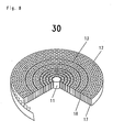
- the ratio of the number of the second column to the number of the first column varies over the area of the flame arrester, in particular the ratio of the number of second gaps decreases to the number of the first column from the inside out.
- This design of the flame arrester is based on the recognition that disc-shaped flame arresters heat up the strongest in the center of the flame arrester, so that there the cooling effect of the second, narrower column can be used intensified.
- the relative number of turns with the second gaps in the center of the flame barrier can be greater than in the outer area.
- the windings of the disc-shaped flame arrester are preferably formed by a corrugated metal strip spirally wound together with a smooth metal band, a first corrugated metal band with larger corrugations forming the turns with the first columns and a corrugated metal band with smaller corrugations forming the convolutions with the second columns.
- the second column can all have the same gap cross-section. But it is also possible that the second column at least two different Have gap cross sections, so that smaller gap cross sections of different sizes are used in conjunction with the first columns. For manufacturing reasons, however, it will usually be preferable to provide only a gap cross-section for the second column.
- first and second column can also take place in that the turns have the first and second gaps along their length, so that in each case a first number of first column and a second number of second column are arranged alternately one behind the other along the length of the turns.
- the corrugation of the corrugated metal strip thus alternately has smaller and longer lengths of the corrugations for forming the first and second gaps.
- the first and second gaps are preferably formed with equal gap lengths.
- the cross-sectional area of the second column should be at most the size of the cross-sectional area of the first column in order to achieve the effect according to the invention clearly enough.
- the choice of the cross-sectional area of the second column naturally depends on the selected number of the second column relative to the number of the first column. This results in a considerable scope for the skilled person in the context of the present invention.
- the ratio of the cross-sectional area of the second (narrower) column to the cross-sectional area of the first (further) column is preferably between 25 and 50%, preferably about 1/3 to 2/3.
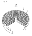
- first embodiment of a flame arrester 10 consists of a cylindrical core 11, around which Windings 12, 13 are spirally wound.
- the turns 12, 13 each consist of a smooth metal strip 14 and a corrugated metal strip 15, which are wound together.
- a metal band 15 is wound with larger shafts 16, while in the winding 13, a corrugated metal strip 15 'is wound with smaller waves.
- continuous first passage column 17 is formed with a larger gap cross-section and in the turns 13 second passage column 18 with a smaller gap cross-section.
- one turn 12 each with first gaps 17 and one turn 13 with second gaps 18 alternate.
- Figures 5 and 6 illustrate the situation at a critical flow rate for the first column 17 in the winding 12. Since the critical volume flow is reached, the flame 7 already burns within the gap 17 and thus leads to a heating of the metallic boundaries of the gap 17th In contrast, the same volume flow in the second gaps 18 leads to a higher gas velocity, so that the flame 7 burns off outside the second gap 18, so that the metallic boundaries of the gap 18 remain well cooled. Since the boundaries of the column 18 are in direct or indirect metallic contact with the boundaries of the column 17, heat dissipation from the hotter columns 17 to the cooler columns 18 takes place so that effective cooling of the first column 17 by the second column 18 occurs ,
- disk-shaped flame arresters 30 regularly heat up more strongly in the core than in the outer region. This is taken into account by the increased arrangement of the turns 13 in the inner region relative to the turns 12, to effect improved cooling in the inner region of the flame arrester 30.
Landscapes
- Health & Medical Sciences (AREA)
- Public Health (AREA)
- Business, Economics & Management (AREA)
- Emergency Management (AREA)
- Gas Burners (AREA)
- Building Environments (AREA)
- Cylinder Crankcases Of Internal Combustion Engines (AREA)
- Insulated Conductors (AREA)
- Gas-Insulated Switchgears (AREA)
- Exhaust Gas After Treatment (AREA)
- Respiratory Apparatuses And Protective Means (AREA)
- Feeding And Controlling Fuel (AREA)
- Extrusion Moulding Of Plastics Or The Like (AREA)
- Thermotherapy And Cooling Therapy Devices (AREA)
- Sampling And Sample Adjustment (AREA)
- Catching Or Destruction (AREA)
- Fuses (AREA)
Claims (15)
- Protection contre le retour de flamme pour un gaz explosif (4) circulant, comprenant une barrière anti-flamme (10, 20, 30) comportant une pluralité de fentes de passage (17, 18) définies, dont la section transversale de fente est réglée en fonction des propriétés du gaz (4) circulant, caractérisée en ce que près des premières fentes (17) ayant la section de fente choisie, sont disposées de secondes fentes (18) ayant une section transversale plus faible.
- Protection contre le retour de flamme selon la revendication 1, caractérisée en ce que les fentes (17, 18) sont réalisées dans une barrière anti-flamme (10, 20, 30) en forme de disque.
- Protection contre le retour de flamme selon la revendication 2, caractérisée en ce que les fentes (17, 18) sont disposées suivant des enroulements (12, 13) circulaires ou en forme de spirale.
- Protection contre le retour de flamme selon la revendication 3, caractérisée en ce qu'elle comprend alternativement un premier nombre d'enroulements (12) avec de premières fentes (17) et un second nombre d'enroulements (13) avec de secondes fentes (18).
- Protection contre le retour de flamme selon la revendication 4, caractérisée en ce qu'elle comprend alternativement un enroulement (12) avec de premières fentes (17) et un enroulement (13) avec de secondes fentes (18).
- Protection contre le retour de flamme selon l'une des revendications 3 à 5, caractérisée en ce que la barrière anti-flamme en forme de disque (10, 20, 30) est réalisée par une bande métallique ondulée (15, 15') enroulée en spirale avec une bande métallique lisse (14), une bande métallique ondulée (15) munie d'ondulations plus grandes (16) formant les enroulements (12) avec les premières fentes (17) et une bande métallique (15') munie d'ondulations plus petites formant les enroulements (13) avec les secondes fentes (18).
- Protection contre le retour de flamme selon la revendication 3, caractérisée en ce que les enroulements (12, 13) présentent sur leur longueur les premières et secondes fentes (17, 18).
- Protection contre le retour de flamme selon la revendication 7, caractérisée en ce que sur la longueur des enroulements (12, 13) sont disposés successivement et alternativement un premier nombre de premières fentes (17) et un second nombre de secondes fentes (18).
- Protection contre le retour de flamme selon la revendication 7 ou 8, caractérisée en ce que la barrière anti-flamme en forme de disque (10, 20, 30) est réalisée par une bande métallique ondulée enroulée en spirale avec une bande métallique lisse (14) et en ce que les ondulations de la bande métallique ondulée présentent alternativement des ondulations de petites ou de grandes longueurs pour réaliser les premières et secondes fentes (17, 18).
- Protection contre le retour de flamme selon l'une des revendications 1 à 9, caractérisée en ce que le rapport du nombre des secondes fentes (18) sur le nombre des premières fentes (17) varie sur la surface de la barrière anti-flamme (30).
- Protection contre le retour de flamme selon la revendication 10, caractérisée en ce que le rapport du nombre de secondes fentes (18) sur le nombre de premières fentes (17) diminue de l'intérieur vers l'extérieur.
- Protection contre le retour de flamme selon l'une des revendications 1 à 11, caractérisée en ce que les secondes fentes (18) présentent toutes la même section transversale de fente.
- Protection contre le retour de flamme selon l'une des revendications 1 à 12, caractérisée en ce que les secondes fentes (18) sont réalisées avec au moins deux sections transversales de fente différentes.
- Protection contre le retour de flamme selon l'une des revendications 1 à 13, caractérisée en ce que les premières et secondes fentes (17, 18) sont réalisées avec des longueurs de fente identiques.
- Protection contre le retour de flamme selon l'une des revendications 1 à 14 caractérisée en ce que la surface de la section transversale des secondes fentes (18) est au maximum égale à 50% de la surface de la section transversale des premières fentes (17).
Priority Applications (3)
| Application Number | Priority Date | Filing Date | Title |
|---|---|---|---|
| PL04738801T PL1528948T3 (pl) | 2003-08-05 | 2004-06-26 | Urządzenie zapobiegające cofaniu płomienia |
| SI200430141T SI1528948T1 (sl) | 2003-08-05 | 2004-06-26 | Zascita pred prebojem plamena |
| CY20071100011T CY1107546T1 (el) | 2003-08-05 | 2007-01-05 | Φλογοπαγιδα |
Applications Claiming Priority (3)
| Application Number | Priority Date | Filing Date | Title |
|---|---|---|---|
| DE10336530A DE10336530B3 (de) | 2003-08-05 | 2003-08-05 | Flammendurchschlagsicherung |
| DE10336530 | 2003-08-05 | ||
| PCT/DE2004/001355 WO2005014112A1 (fr) | 2003-08-05 | 2004-06-26 | Systeme de protection contre le retour de flamme |
Publications (2)
| Publication Number | Publication Date |
|---|---|
| EP1528948A1 EP1528948A1 (fr) | 2005-05-11 |
| EP1528948B1 true EP1528948B1 (fr) | 2006-11-02 |
Family
ID=34072078
Family Applications (1)
| Application Number | Title | Priority Date | Filing Date |
|---|---|---|---|
| EP04738801A Expired - Lifetime EP1528948B1 (fr) | 2003-08-05 | 2004-06-26 | Systeme de protection contre le retour de flamme |
Country Status (16)
| Country | Link |
|---|---|
| US (1) | US7241137B2 (fr) |
| EP (1) | EP1528948B1 (fr) |
| JP (1) | JP4399458B2 (fr) |
| KR (1) | KR101052405B1 (fr) |
| AT (1) | ATE344093T1 (fr) |
| BR (1) | BRPI0405658A (fr) |
| CA (1) | CA2496674C (fr) |
| CY (1) | CY1107546T1 (fr) |
| DE (2) | DE10336530B3 (fr) |
| DK (1) | DK1528948T3 (fr) |
| ES (1) | ES2273263T3 (fr) |
| NO (1) | NO20050104L (fr) |
| PL (1) | PL1528948T3 (fr) |
| PT (1) | PT1528948E (fr) |
| TW (1) | TWI312049B (fr) |
| WO (1) | WO2005014112A1 (fr) |
Families Citing this family (46)
| Publication number | Priority date | Publication date | Assignee | Title |
|---|---|---|---|---|
| DE10326150B4 (de) * | 2003-06-06 | 2005-12-15 | Leinemann Gmbh & Co. Kg | Dauerbrandsichere Flammensperre |
| DE102006026510B3 (de) * | 2006-06-06 | 2007-05-24 | Leinemann Gmbh & Co. Kg | Flammensperreinsatz und Verfahren zu seiner Herstellung |
| DE102006026779A1 (de) * | 2006-06-07 | 2007-12-20 | Leinemann Gmbh & Co. Kg | Flammensperranordnung und Verfahren zum Einbringen von Bohrungen in eine Flammensperranordnung |
| ATE449937T1 (de) * | 2006-09-06 | 2009-12-15 | Electrolux Home Prod Corp | Gasbrenner für kochgeräte |
| US8230673B2 (en) * | 2006-12-04 | 2012-07-31 | Firestar Engineering, Llc | Rocket engine injectorhead with flashback barrier |
| US8230672B2 (en) * | 2006-12-04 | 2012-07-31 | Firestar Engineering, Llc | Spark-integrated propellant injector head with flashback barrier |
| US8572946B2 (en) | 2006-12-04 | 2013-11-05 | Firestar Engineering, Llc | Microfluidic flame barrier |
| US20080163862A1 (en) * | 2007-01-04 | 2008-07-10 | Outdoor Polymer Systems Inc. | Modular outdoor kitchen apparatus and methods |
| JP5049737B2 (ja) * | 2007-10-23 | 2012-10-17 | 本田技研工業株式会社 | 車両用燃料タンクの給油口装置 |
| WO2009062183A1 (fr) * | 2007-11-09 | 2009-05-14 | Firestar Engineering, Llc | Monergols à oxyde d'azote mélangé à un combustible |
| CH701405A1 (de) * | 2009-07-03 | 2011-01-14 | Johannes Schwarz | Brandhemmender Körper und Band zur Herstellung desselben. |
| US20110005194A1 (en) * | 2009-07-07 | 2011-01-13 | Firestar Engineering, Llc | Flashback shut-off |
| KR20110030219A (ko) * | 2009-09-17 | 2011-03-23 | 현우에스엠티 주식회사 | 내연기관의 화염분출방지용 어레스트 장치 |
| WO2011091162A1 (fr) * | 2010-01-20 | 2011-07-28 | Firestar Engineering, Llc | Chambre de combustion isolée |
| WO2011152912A2 (fr) * | 2010-03-12 | 2011-12-08 | Firestar Engineering, Llc | Tuyère de fusée à chambre de combustion supersonique |
| DE102010056590A1 (de) * | 2010-12-30 | 2012-07-05 | Leinemann Gmbh & Co. Kg | Flammendurchschlagsicherung |
| US20120189966A1 (en) * | 2011-01-21 | 2012-07-26 | Brooker Dwight E | Detonation flame arrestor including a transition point/attenuation matrix and torturous path media |
| US10571124B2 (en) | 2013-02-14 | 2020-02-25 | Clearsign Combustion Corporation | Selectable dilution low NOx burner |
| US10386062B2 (en) | 2013-02-14 | 2019-08-20 | Clearsign Combustion Corporation | Method for operating a combustion system including a perforated flame holder |
| US10119704B2 (en) | 2013-02-14 | 2018-11-06 | Clearsign Combustion Corporation | Burner system including a non-planar perforated flame holder |
| CA2892231A1 (fr) | 2013-02-14 | 2014-08-21 | Clearsign Combustion Corporation | Bruleur a faible degagement de nox a niveau de dilution selectionnable |
| CA2892236A1 (fr) | 2013-02-14 | 2014-08-21 | Clearsign Combustion Corporation | Systeme de combustion de carburant avec un support de reaction perfore |
| DE102013208081A1 (de) * | 2013-05-02 | 2014-11-06 | Robert Bosch Gmbh | Fluidverteiler, Elektrolyseur sowie Verfahren zur Funktion eines Fluidverteilers |
| US10371408B2 (en) | 2013-07-15 | 2019-08-06 | Carrier Corporation | Flame arrestors for use with a HVAC/R system |
| US9205292B2 (en) | 2013-09-09 | 2015-12-08 | Empyreus Solutions Llc | Flame arrester with flexible porous cover |
| EP3049721A4 (fr) * | 2013-09-23 | 2017-09-20 | Clearsign Combustion Corporation | Système de brûleur utilisant de multiples stabilisateurs de flamme perforés et procédé de fonctionnement |
| EP3055616B1 (fr) * | 2013-10-07 | 2020-12-09 | ClearSign Technologies Corporation | Brûleur à prémélangé à stabilisateur perforé |
| US20160047317A1 (en) * | 2014-08-14 | 2016-02-18 | General Electric Company | Fuel injector assemblies in combustion turbine engines |
| US10767859B2 (en) * | 2014-08-19 | 2020-09-08 | Adler Hot Oil Service, LLC | Wellhead gas heater |
| US9731155B2 (en) | 2014-09-05 | 2017-08-15 | Empyreus Solutions Llc | Flame arrester with porous sleeve |
| WO2016134061A1 (fr) | 2015-02-17 | 2016-08-25 | Clearsign Combustion Corporation | Stabilisateur de flamme perforé à buse de carburant réglable |
| US10890325B2 (en) * | 2015-04-17 | 2021-01-12 | Eaton Intelligent Power Limited | Flame arrestor |
| US20170051913A1 (en) * | 2015-08-18 | 2017-02-23 | Clearsign Combustion Corporation | Combustion system with a perforated flame holder and an external flue gas recirculation apparatus |
| KR101616506B1 (ko) | 2015-11-13 | 2016-04-28 | 이경로 | 미분무 소화가 가능한 원유 저장탱크용 브리더밸브 |
| EP4317781A3 (fr) | 2016-04-29 | 2024-04-03 | ClearSign Technologies Corporation | Système de brûleur avec stabilisateurs de flamme transversaux discrets |
| US10619848B2 (en) * | 2016-05-31 | 2020-04-14 | Sellers Manufacturing Co. | Burner and air supply assembly for horizontal immersion tube boilers |
| US9987508B2 (en) | 2016-08-31 | 2018-06-05 | Emerson Process Management Regulator Technologies Tulsa, Llc | Hybrid composite flame cell |
| US20180056100A1 (en) | 2016-08-31 | 2018-03-01 | Emerson Process Management Regulator Technologies Tulsa, Llc | Method for Manufacturing a Flame Arrestor |
| US10539326B2 (en) | 2016-09-07 | 2020-01-21 | Clearsign Combustion Corporation | Duplex burner with velocity-compensated mesh and thickness |
| CA3037301C (fr) * | 2016-09-16 | 2023-08-08 | Cv Technology, Inc. | Systeme, appareil et procede pour arrete-flammes |
| KR102046455B1 (ko) * | 2017-10-30 | 2019-11-19 | 두산중공업 주식회사 | 연료 노즐, 이를 포함하는 연소기 및 가스 터빈 |
| KR102228104B1 (ko) * | 2018-05-28 | 2021-03-16 | 주식회사 탑세이프 | 화염 차단 장치 |
| US11992721B2 (en) * | 2020-07-08 | 2024-05-28 | Rosemount Inc. | Flame arrester for process devices |
| CN112032718B (zh) * | 2020-09-08 | 2025-03-04 | 华帝股份有限公司 | 红外线金属蜂窝体和红外线金属燃烧器 |
| DE102021121764A1 (de) | 2021-08-23 | 2023-02-23 | Viessmann Climate Solutions Se | Gasbrennervorrichtung |
| USD1054527S1 (en) | 2022-02-12 | 2024-12-17 | Mark W Wyne | Flame arrestor |
Family Cites Families (12)
| Publication number | Priority date | Publication date | Assignee | Title |
|---|---|---|---|---|
| US1681698A (en) * | 1926-09-16 | 1928-08-21 | Brooks Engineering Corp | Flame arrester |
| US3173411A (en) * | 1962-10-22 | 1965-03-16 | Enardo Mfg Company | Flame arrestor |
| JPS59136140A (ja) * | 1983-01-25 | 1984-08-04 | Babcock Hitachi Kk | 燃焼用触媒体 |
| US4909730A (en) * | 1989-01-23 | 1990-03-20 | Westech Industrial Ltd. | Flame arrester having detonation-attenuating means |
| US4917599A (en) * | 1988-12-29 | 1990-04-17 | Hasselmann Detley E M | Burner for combustible gases |
| US5346389A (en) | 1989-02-24 | 1994-09-13 | W. R. Grace & Co.-Conn. | Combustion apparatus for high-temperature environment |
| SG49198A1 (en) * | 1992-06-30 | 1998-05-18 | Chem Mech Engineering | Flame arrestor apparatus |
| JPH0814509A (ja) * | 1994-07-01 | 1996-01-19 | Paloma Ind Ltd | パルス燃焼器 |
| DE19818572C1 (de) * | 1998-04-25 | 1999-11-11 | Leinemann Gmbh & Co | Verfahren zum Unschädlichmachen einer Detonationsfront und Detonationssicherung |
| US6179608B1 (en) * | 1999-05-28 | 2001-01-30 | Precision Combustion, Inc. | Swirling flashback arrestor |
| US6338319B1 (en) * | 1999-11-12 | 2002-01-15 | Water Heater Industry Joint Research & Development | Water heater with flammable vapor flame arrestor and method of operation |
| JP2001090914A (ja) * | 2000-08-29 | 2001-04-03 | Paloma Ind Ltd | フレームトラップ |
-
2003
- 2003-08-05 DE DE10336530A patent/DE10336530B3/de not_active Expired - Fee Related
-
2004
- 2004-06-26 WO PCT/DE2004/001355 patent/WO2005014112A1/fr not_active Ceased
- 2004-06-26 JP JP2006522206A patent/JP4399458B2/ja not_active Expired - Fee Related
- 2004-06-26 EP EP04738801A patent/EP1528948B1/fr not_active Expired - Lifetime
- 2004-06-26 PT PT04738801T patent/PT1528948E/pt unknown
- 2004-06-26 US US10/525,075 patent/US7241137B2/en not_active Expired - Fee Related
- 2004-06-26 DK DK04738801T patent/DK1528948T3/da active
- 2004-06-26 AT AT04738801T patent/ATE344093T1/de active
- 2004-06-26 DE DE502004001891T patent/DE502004001891D1/de not_active Expired - Lifetime
- 2004-06-26 ES ES04738801T patent/ES2273263T3/es not_active Expired - Lifetime
- 2004-06-26 CA CA2496674A patent/CA2496674C/fr not_active Expired - Fee Related
- 2004-06-26 PL PL04738801T patent/PL1528948T3/pl unknown
- 2004-06-26 BR BR0405658-2A patent/BRPI0405658A/pt active Search and Examination
- 2004-06-26 KR KR1020057002815A patent/KR101052405B1/ko not_active Expired - Fee Related
- 2004-06-29 TW TW093119002A patent/TWI312049B/zh not_active IP Right Cessation
-
2005
- 2005-01-07 NO NO20050104A patent/NO20050104L/no not_active Application Discontinuation
-
2007
- 2007-01-05 CY CY20071100011T patent/CY1107546T1/el unknown
Also Published As
| Publication number | Publication date |
|---|---|
| DE502004001891D1 (de) | 2006-12-14 |
| ES2273263T3 (es) | 2007-05-01 |
| JP4399458B2 (ja) | 2010-01-13 |
| PT1528948E (pt) | 2007-01-31 |
| KR20060066047A (ko) | 2006-06-15 |
| CA2496674A1 (fr) | 2005-02-17 |
| CA2496674C (fr) | 2010-10-05 |
| CY1107546T1 (el) | 2013-03-13 |
| BRPI0405658A (pt) | 2005-07-19 |
| ATE344093T1 (de) | 2006-11-15 |
| TW200506282A (en) | 2005-02-16 |
| KR101052405B1 (ko) | 2011-07-28 |
| TWI312049B (en) | 2009-07-11 |
| WO2005014112A1 (fr) | 2005-02-17 |
| PL1528948T3 (pl) | 2007-03-30 |
| US20060008755A1 (en) | 2006-01-12 |
| JP2007501032A (ja) | 2007-01-25 |
| NO20050104L (no) | 2005-02-17 |
| EP1528948A1 (fr) | 2005-05-11 |
| DE10336530B3 (de) | 2005-02-17 |
| US7241137B2 (en) | 2007-07-10 |
| HK1075218A1 (en) | 2005-12-09 |
| DK1528948T3 (da) | 2007-02-26 |
Similar Documents
| Publication | Publication Date | Title |
|---|---|---|
| EP1528948B1 (fr) | Systeme de protection contre le retour de flamme | |
| EP1631358B1 (fr) | Pare-flamme a incombustibilite permanente | |
| DE69305351T3 (de) | Flammen- und explosionsschutzsicherung | |
| DE19622257B4 (de) | Luft-Dielektrik-Koaxialkabel mit hohlem Abstandselement | |
| DE2827188C2 (de) | Bohrlochsieb | |
| EP1240923B1 (fr) | Dispositif pare-flamme | |
| DE3208828C2 (fr) | ||
| DE2020062B2 (de) | Flammenschranke zum verhindern des flammenaustritts aus explosions-entlastungsventilen | |
| DE2659085A1 (de) | Flammensperre | |
| AT408839B (de) | Flammensperre | |
| DE102006026510B3 (de) | Flammensperreinsatz und Verfahren zu seiner Herstellung | |
| WO2012089187A2 (fr) | Protection contre le retour de flammes | |
| EP0729290A2 (fr) | Unité de chauffage par radiation et procédé de sa fabrication | |
| DE2208137A1 (de) | Vertikaler Rohrofen für hohen Arbeitsdruck | |
| DE20321089U1 (de) | Dauerbrandsichere Flammensperre | |
| DE602004003972T2 (de) | Zündkerze | |
| EP0869315A2 (fr) | Brûleur atmosphérique à gaz | |
| EP2332617A1 (fr) | Dispositif anti-retour de flammes pour installations d'extraction | |
| EP2201983B1 (fr) | Dispositif de sécurité pour des systèmes conductif de gaz | |
| AT504898B1 (de) | Flammfilter | |
| AT250544B (de) | Rückschlagsicherung gegen den Durchtritt von Flammen in Leitungen für brennbare Flüssigkeiten oder Gase, insbesondere flüssige oder gasförmige Brenn- oder Treibstoffe | |
| DE2850618C3 (de) | Entlüftung für Flugzeugtanks | |
| DE19824851A1 (de) | Sicherung | |
| DE1501503A1 (de) | Waermeaustauscher mit vergroesserter Oberflaeche und Verfahren zu seiner Herstellung | |
| DE3309930C2 (fr) |
Legal Events
| Date | Code | Title | Description |
|---|---|---|---|
| PUAI | Public reference made under article 153(3) epc to a published international application that has entered the european phase |
Free format text: ORIGINAL CODE: 0009012 |
|
| 17P | Request for examination filed |
Effective date: 20050107 |
|
| AK | Designated contracting states |
Kind code of ref document: A1 Designated state(s): AT BE BG CH CY CZ DE DK EE ES FI FR GB GR HU IE IT LI LU MC NL PL PT RO SE SI SK TR |
|
| AX | Request for extension of the european patent |
Extension state: AL HR LT LV MK |
|
| REG | Reference to a national code |
Ref country code: HK Ref legal event code: DE Ref document number: 1075218 Country of ref document: HK |
|
| RAP1 | Party data changed (applicant data changed or rights of an application transferred) |
Owner name: LEINEMANN GMBH & CO. KG |
|
| GRAP | Despatch of communication of intention to grant a patent |
Free format text: ORIGINAL CODE: EPIDOSNIGR1 |
|
| GRAS | Grant fee paid |
Free format text: ORIGINAL CODE: EPIDOSNIGR3 |
|
| GRAA | (expected) grant |
Free format text: ORIGINAL CODE: 0009210 |
|
| AK | Designated contracting states |
Kind code of ref document: B1 Designated state(s): AT BE BG CH CY CZ DE DK EE ES FI FR GB GR HU IE IT LI LU MC NL PL PT RO SE SI SK TR |
|
| DAX | Request for extension of the european patent (deleted) | ||
| REG | Reference to a national code |
Ref country code: GB Ref legal event code: FG4D Free format text: NOT ENGLISH |
|
| REG | Reference to a national code |
Ref country code: IE Ref legal event code: FG4D Free format text: LANGUAGE OF EP DOCUMENT: GERMAN |
|
| REG | Reference to a national code |
Ref country code: CH Ref legal event code: EP |
|
| REG | Reference to a national code |
Ref country code: RO Ref legal event code: EPE |
|
| GBT | Gb: translation of ep patent filed (gb section 77(6)(a)/1977) |
Effective date: 20061109 |
|
| REF | Corresponds to: |
Ref document number: 502004001891 Country of ref document: DE Date of ref document: 20061214 Kind code of ref document: P |
|
| REG | Reference to a national code |
Ref country code: PT Ref legal event code: SC4A Free format text: AVAILABILITY OF NATIONAL TRANSLATION Effective date: 20061211 |
|
| REG | Reference to a national code |
Ref country code: SE Ref legal event code: TRGR |
|
| REG | Reference to a national code |
Ref country code: EE Ref legal event code: FG4A Ref document number: E000752 Country of ref document: EE Effective date: 20070105 Ref country code: GR Ref legal event code: EP Ref document number: 20070400109 Country of ref document: GR |
|
| REG | Reference to a national code |
Ref country code: DK Ref legal event code: T3 |
|
| REG | Reference to a national code |
Ref country code: CH Ref legal event code: NV Representative=s name: BRAUNPAT BRAUN EDER AG |
|
| REG | Reference to a national code |
Ref country code: HK Ref legal event code: GR Ref document number: 1075218 Country of ref document: HK |
|
| REG | Reference to a national code |
Ref country code: PL Ref legal event code: T3 |
|
| REG | Reference to a national code |
Ref country code: ES Ref legal event code: FG2A Ref document number: 2273263 Country of ref document: ES Kind code of ref document: T3 |
|
| ET | Fr: translation filed | ||
| REG | Reference to a national code |
Ref country code: HU Ref legal event code: AG4A Ref document number: E001519 Country of ref document: HU |
|
| PLBE | No opposition filed within time limit |
Free format text: ORIGINAL CODE: 0009261 |
|
| STAA | Information on the status of an ep patent application or granted ep patent |
Free format text: STATUS: NO OPPOSITION FILED WITHIN TIME LIMIT |
|
| 26N | No opposition filed |
Effective date: 20070803 |
|
| REG | Reference to a national code |
Ref country code: EE Ref legal event code: MM4A Ref document number: E000752 Country of ref document: EE Effective date: 20070630 Ref country code: EE Ref legal event code: HC1A Ref document number: E000752 Country of ref document: EE |
|
| PG25 | Lapsed in a contracting state [announced via postgrant information from national office to epo] |
Ref country code: IE Free format text: LAPSE BECAUSE OF NON-PAYMENT OF DUE FEES Effective date: 20070626 Ref country code: EE Free format text: LAPSE BECAUSE OF NON-PAYMENT OF DUE FEES Effective date: 20070630 |
|
| PG25 | Lapsed in a contracting state [announced via postgrant information from national office to epo] |
Ref country code: CY Free format text: LAPSE BECAUSE OF NON-PAYMENT OF DUE FEES Effective date: 20070626 Ref country code: RO Free format text: LAPSE BECAUSE OF NON-PAYMENT OF DUE FEES Effective date: 20061102 |
|
| REG | Reference to a national code |
Ref country code: IE Ref legal event code: NE4A |
|
| PGRI | Patent reinstated in contracting state [announced from national office to epo] |
Ref country code: IE Effective date: 20090122 |
|
| REG | Reference to a national code |
Ref country code: IE Ref legal event code: NF4A Effective date: 20090122 |
|
| PGFP | Annual fee paid to national office [announced via postgrant information from national office to epo] |
Ref country code: GR Payment date: 20110627 Year of fee payment: 8 Ref country code: IE Payment date: 20110621 Year of fee payment: 8 Ref country code: MC Payment date: 20110621 Year of fee payment: 8 Ref country code: LU Payment date: 20110622 Year of fee payment: 8 Ref country code: SE Payment date: 20110622 Year of fee payment: 8 Ref country code: PT Payment date: 20110616 Year of fee payment: 8 Ref country code: CH Payment date: 20110623 Year of fee payment: 8 |
|
| PGFP | Annual fee paid to national office [announced via postgrant information from national office to epo] |
Ref country code: BG Payment date: 20110622 Year of fee payment: 8 Ref country code: FI Payment date: 20110620 Year of fee payment: 8 Ref country code: SI Payment date: 20110615 Year of fee payment: 8 Ref country code: RO Payment date: 20110530 Year of fee payment: 8 Ref country code: SK Payment date: 20110621 Year of fee payment: 8 |
|
| PGFP | Annual fee paid to national office [announced via postgrant information from national office to epo] |
Ref country code: CY Payment date: 20110504 Year of fee payment: 8 |
|
| PGFP | Annual fee paid to national office [announced via postgrant information from national office to epo] |
Ref country code: CZ Payment date: 20120621 Year of fee payment: 9 Ref country code: DK Payment date: 20120625 Year of fee payment: 9 Ref country code: TR Payment date: 20120619 Year of fee payment: 9 Ref country code: HU Payment date: 20120626 Year of fee payment: 9 Ref country code: NL Payment date: 20120628 Year of fee payment: 9 |
|
| PGFP | Annual fee paid to national office [announced via postgrant information from national office to epo] |
Ref country code: GB Payment date: 20120621 Year of fee payment: 9 Ref country code: FR Payment date: 20120705 Year of fee payment: 9 Ref country code: PL Payment date: 20120511 Year of fee payment: 9 |
|
| PGFP | Annual fee paid to national office [announced via postgrant information from national office to epo] |
Ref country code: IT Payment date: 20120623 Year of fee payment: 9 |
|
| PGFP | Annual fee paid to national office [announced via postgrant information from national office to epo] |
Ref country code: BE Payment date: 20120622 Year of fee payment: 9 |
|
| PGFP | Annual fee paid to national office [announced via postgrant information from national office to epo] |
Ref country code: DE Payment date: 20120710 Year of fee payment: 9 Ref country code: ES Payment date: 20120628 Year of fee payment: 9 |
|
| REG | Reference to a national code |
Ref country code: PT Ref legal event code: MM4A Free format text: LAPSE DUE TO NON-PAYMENT OF FEES Effective date: 20121226 |
|
| REG | Reference to a national code |
Ref country code: SE Ref legal event code: EUG |
|
| PG25 | Lapsed in a contracting state [announced via postgrant information from national office to epo] |
Ref country code: FI Free format text: LAPSE BECAUSE OF NON-PAYMENT OF DUE FEES Effective date: 20120626 Ref country code: MC Free format text: LAPSE BECAUSE OF NON-PAYMENT OF DUE FEES Effective date: 20120630 |
|
| REG | Reference to a national code |
Ref country code: CH Ref legal event code: PL |
|
| REG | Reference to a national code |
Ref country code: CH Ref legal event code: PL |
|
| PG25 | Lapsed in a contracting state [announced via postgrant information from national office to epo] |
Ref country code: PT Free format text: LAPSE BECAUSE OF NON-PAYMENT OF DUE FEES Effective date: 20121226 Ref country code: SE Free format text: LAPSE BECAUSE OF NON-PAYMENT OF DUE FEES Effective date: 20120627 |
|
| REG | Reference to a national code |
Ref country code: SK Ref legal event code: MM4A Ref document number: E 1306 Country of ref document: SK Effective date: 20120626 Ref country code: GR Ref legal event code: ML Ref document number: 20070400109 Country of ref document: GR Effective date: 20130104 |
|
| REG | Reference to a national code |
Ref country code: IE Ref legal event code: MM4A |
|
| PGFP | Annual fee paid to national office [announced via postgrant information from national office to epo] |
Ref country code: AT Payment date: 20120620 Year of fee payment: 9 |
|
| REG | Reference to a national code |
Ref country code: SI Ref legal event code: KO00 Effective date: 20130206 |
|
| PG25 | Lapsed in a contracting state [announced via postgrant information from national office to epo] |
Ref country code: IE Free format text: LAPSE BECAUSE OF NON-PAYMENT OF DUE FEES Effective date: 20120626 Ref country code: RO Free format text: LAPSE BECAUSE OF NON-PAYMENT OF DUE FEES Effective date: 20120626 Ref country code: CH Free format text: LAPSE BECAUSE OF NON-PAYMENT OF DUE FEES Effective date: 20120630 Ref country code: LI Free format text: LAPSE BECAUSE OF NON-PAYMENT OF DUE FEES Effective date: 20120630 |
|
| PG25 | Lapsed in a contracting state [announced via postgrant information from national office to epo] |
Ref country code: GR Free format text: LAPSE BECAUSE OF NON-PAYMENT OF DUE FEES Effective date: 20130104 Ref country code: SI Free format text: LAPSE BECAUSE OF NON-PAYMENT OF DUE FEES Effective date: 20120627 Ref country code: SK Free format text: LAPSE BECAUSE OF NON-PAYMENT OF DUE FEES Effective date: 20120626 |
|
| PG25 | Lapsed in a contracting state [announced via postgrant information from national office to epo] |
Ref country code: CY Free format text: LAPSE BECAUSE OF NON-PAYMENT OF DUE FEES Effective date: 20120626 |
|
| BERE | Be: lapsed |
Owner name: LEINEMANN G.M.B.H. & CO. KG Effective date: 20130630 |
|
| REG | Reference to a national code |
Ref country code: NL Ref legal event code: V1 Effective date: 20140101 |
|
| PG25 | Lapsed in a contracting state [announced via postgrant information from national office to epo] |
Ref country code: CZ Free format text: LAPSE BECAUSE OF NON-PAYMENT OF DUE FEES Effective date: 20130626 |
|
| REG | Reference to a national code |
Ref country code: DK Ref legal event code: EBP Effective date: 20130630 |
|
| REG | Reference to a national code |
Ref country code: AT Ref legal event code: MM01 Ref document number: 344093 Country of ref document: AT Kind code of ref document: T Effective date: 20130626 |
|
| GBPC | Gb: european patent ceased through non-payment of renewal fee |
Effective date: 20130626 |
|
| REG | Reference to a national code |
Ref country code: DE Ref legal event code: R119 Ref document number: 502004001891 Country of ref document: DE Effective date: 20140101 |
|
| REG | Reference to a national code |
Ref country code: FR Ref legal event code: ST Effective date: 20140228 |
|
| PG25 | Lapsed in a contracting state [announced via postgrant information from national office to epo] |
Ref country code: BE Free format text: LAPSE BECAUSE OF NON-PAYMENT OF DUE FEES Effective date: 20130630 |
|
| PG25 | Lapsed in a contracting state [announced via postgrant information from national office to epo] |
Ref country code: GB Free format text: LAPSE BECAUSE OF NON-PAYMENT OF DUE FEES Effective date: 20130626 Ref country code: HU Free format text: LAPSE BECAUSE OF NON-PAYMENT OF DUE FEES Effective date: 20130627 Ref country code: DE Free format text: LAPSE BECAUSE OF NON-PAYMENT OF DUE FEES Effective date: 20140101 Ref country code: NL Free format text: LAPSE BECAUSE OF NON-PAYMENT OF DUE FEES Effective date: 20140101 |
|
| PG25 | Lapsed in a contracting state [announced via postgrant information from national office to epo] |
Ref country code: FR Free format text: LAPSE BECAUSE OF NON-PAYMENT OF DUE FEES Effective date: 20130701 Ref country code: AT Free format text: LAPSE BECAUSE OF NON-PAYMENT OF DUE FEES Effective date: 20130626 Ref country code: IT Free format text: LAPSE BECAUSE OF NON-PAYMENT OF DUE FEES Effective date: 20130626 Ref country code: LU Free format text: LAPSE BECAUSE OF NON-PAYMENT OF DUE FEES Effective date: 20120626 |
|
| REG | Reference to a national code |
Ref country code: ES Ref legal event code: FD2A Effective date: 20140707 |
|
| PG25 | Lapsed in a contracting state [announced via postgrant information from national office to epo] |
Ref country code: BG Free format text: LAPSE BECAUSE OF NON-PAYMENT OF DUE FEES Effective date: 20120630 |
|
| PG25 | Lapsed in a contracting state [announced via postgrant information from national office to epo] |
Ref country code: DK Free format text: LAPSE BECAUSE OF NON-PAYMENT OF DUE FEES Effective date: 20130630 |
|
| REG | Reference to a national code |
Ref country code: PL Ref legal event code: LAPE |
|
| PG25 | Lapsed in a contracting state [announced via postgrant information from national office to epo] |
Ref country code: PL Free format text: LAPSE BECAUSE OF NON-PAYMENT OF DUE FEES Effective date: 20130626 Ref country code: ES Free format text: LAPSE BECAUSE OF NON-PAYMENT OF DUE FEES Effective date: 20130627 |
|
| PG25 | Lapsed in a contracting state [announced via postgrant information from national office to epo] |
Ref country code: TR Free format text: LAPSE BECAUSE OF NON-PAYMENT OF DUE FEES Effective date: 20130626 |