EP1528836A2 - Porting and heat removal in acoustic devices - Google Patents
Porting and heat removal in acoustic devices Download PDFInfo
- Publication number
- EP1528836A2 EP1528836A2 EP04105332A EP04105332A EP1528836A2 EP 1528836 A2 EP1528836 A2 EP 1528836A2 EP 04105332 A EP04105332 A EP 04105332A EP 04105332 A EP04105332 A EP 04105332A EP 1528836 A2 EP1528836 A2 EP 1528836A2
- Authority
- EP
- European Patent Office
- Prior art keywords
- port
- enclosure
- acoustic
- airflow
- opening
- Prior art date
- Legal status (The legal status is an assumption and is not a legal conclusion. Google has not performed a legal analysis and makes no representation as to the accuracy of the status listed.)
- Granted
Links
Images


Classifications
-
- H—ELECTRICITY
- H04—ELECTRIC COMMUNICATION TECHNIQUE
- H04R—LOUDSPEAKERS, MICROPHONES, GRAMOPHONE PICK-UPS OR LIKE ACOUSTIC ELECTROMECHANICAL TRANSDUCERS; DEAF-AID SETS; PUBLIC ADDRESS SYSTEMS
- H04R9/00—Transducers of moving-coil, moving-strip, or moving-wire type
- H04R9/02—Details
- H04R9/022—Cooling arrangements
-
- H—ELECTRICITY
- H04—ELECTRIC COMMUNICATION TECHNIQUE
- H04R—LOUDSPEAKERS, MICROPHONES, GRAMOPHONE PICK-UPS OR LIKE ACOUSTIC ELECTROMECHANICAL TRANSDUCERS; DEAF-AID SETS; PUBLIC ADDRESS SYSTEMS
- H04R1/00—Details of transducers, loudspeakers or microphones
- H04R1/02—Casings; Cabinets ; Supports therefor; Mountings therein
Definitions
- the invention relates to porting and heat removal in acoustic devices, and more particularly to heat removal from ported acoustic enclosures. It is an important object of the invention to provide an improved apparatus fo r porting. It is another object to remove undesired heat from an acoustic device.
- an electroacoustical device comprises a loudspeaker enclosure including a first acoustic port, an acoustic driver mounted in the loudspeaker enclosure; and a heat producing device.
- the acoustic driver and the acoustic port are constructed and arranged to coact to provide a cooling, substantially unidirectional airflow across the heat producing device, thereby transferring heat from the heat producing device.
- an electroacoustical device in another aspect of the invention, includes an acoustic enclosure, a first acoustic port in the acoustic enclosure, an acoustic driver mounted in the acoustic enclosure for cau sing a first airflow in the port.
- the first airflow flows alternatingly inward and outward in the port.
- the device further includes a heat producing device.
- the acoustic port is constructed and arranged so that the first airflow creates a substantially unidirectional second airflow.
- the device also includes structure for causing the unidirectional airflow to flow across the heat producing device.
- a loudspeaker enclosure having an interior and an exterior includes a fi rst port having a first end having a cross-sectional area and a second end having a cross-sectional area, wherein the first end cross-sectional area is greater than the second end cross-sectional area.
- the first end abuts the interior, and the second end abuts the exterior.
- the enclosure also includes a second port. The first port is typically located below the second port.
- a loudspeaker in another aspect of the invention, includes an electroacoustical transducer and a loudspeaker enclosure.
- the loudspe aker enclosure has a first port having an interior end and an exterior end, each having cross-sectional area.
- the exterior end cross-sectional area is larger than the interior end cross-sectional area.
- the device also includes a second port having an interior end and an exterior end. The first port is typically located above the second port.
- a loudspeaker enclosure in another aspect of the invention, includes a first port having an interior end and an exterior end, each having a cross-sectional area.
- the first port interior end cross-sectional area is smaller than the first port exterior end cross-sectional area.
- the enclosure also includes a second port having an interior end and an exterior end, each end having a cross-sectional area.
- the second port interior end cross-sectional area is larger than the second port exterior end cross -sectional area.
- an electroacoustical device in another aspect of the invention, includes a first enclosure having a port having a terminal point for an outward airflow to exit the enclosure to an ambient environment and for an inward airflow to enter the enclosure.
- the device also includes an electroacoustical transducer, comprising a vibratile surface for generating pressure waves resulting in the outward airflow and the inward airflow.
- the device also includes a second en closure having a first opening and a second opening.
- the port terminal point is positioned near the first opening and oriented so that the port terminal outward flow flows toward the second opening.
- the port and the electroacoustical transducer coact to cause a substantially unidirectional airflow into the first opening.
- the enclosure includes a port having an exit for radiating pressure waves.
- the electroacoustical device further includes an electroacoustical transducer, positioned in the acoustic enclosure, to provide the pressure waves.
- the device also includes an elongated second enclosure having a first extremity and a second extremity in a direction of elongation. There is a first opening at the first extremity and a second opening at the second extremity.
- the port exit is positioned in the first opening so that the pressure waves are radiated into the second enclosure through the first opening toward the second opening.
- the device also includes a mounting position for a heat producing device in the elongated second enclosure, positioned so that air flowing into the opening from the ambient environment flows across the mounting position.
- an electroacoustical device in still another aspect of the invention, includes a first enclosure having a port having a terminal point for an outward airflow to exit the enclosure and for an inward airflow to enter the enclosure.
- the device also includes an electroacoustical transducer, having a vibratile surface, mounted in the first enclosure, for generating pressure waves resulting in the outward airflow and the inward airflow.
- the device also includes a second enclosure havi ng a first opening and a second opening.
- the port terminal point is positioned with the port terminal point in the second enclosure, oriented so that the port terminal outward flow flows toward the second opening.
- the port and the electroacoustical transducer coact to cause a substantially unidirectional airflow into the first opening.
- a loudspeaker enclosure having a loudspeaker driver and a port tube formed with a vent intermediate its ends constructed and arranged to introduce leakage resistance into the port tube that reduces the Q of at least one standing wave excited in the port tube when acoustic energy is transmitted therethrough. Venting may occur into the acoustic enclosure, into the space outside the enclosure, to a different part of the port tube, into a small volume, into a closed end resonant tube, or other suitable volume.
- a loudspeaker 110 includes an enclosure 112 and an acoustic driver 114.
- Ports 116 and 118 are flared.
- the upper port 118 is flared inwardly, that is, the interior end 118i has a larger cross-sectional area than the exterior end 118e.
- the lower port is flared outwardly, that is, the exterior end 116e has a larger cross-sectional area than the interior end 116i.
- Loudspeaker 10 includes an enclosure 12 and an acoustic driver 14 having a motor structure 15.
- In the enclosure are two ports, 16 and 18, positioned so that one port 16 is positioned lower in the enclosure 12 than the other port 18.
- Lower port 16 is flared inwardly, that is, interior end 16i has a larger cross -sectional area than the exterior end 16e.
- Upper port 18 is flared outwardly, that is, exterior end 18e has a larger cross-sectional area than the interior end 18i.
- the flares of port 16 and 18 are exaggerated. Actual dimensions of an exemplary port are presented below.
- In the enclosure there are heat producing elements.
- the heat producing elements may include the motor structure 15 of the acoustic driver, or an optional heat producing device 20, such as a power supply or amplifier for loudspeaker 10 or for another loudspeaker, not shown, or both.
- Optional heat producing device 20 may be positioned lower than upper port 18 for better results. It may be advantageous to remove heat from motor structure 15, positioning it lower than upper port 18 for better results.
- a surface, such as cone 13, of acoustic driver 14 is driven by motor structure 15 so that the cone 13 vibrates in the direction indicated by arrow 17, radiating sound waves, in this case to the exterior 24 of the enclosure and the interior 22 of the enclosure.
- the motor structure 15 In driving the acoustic driver cone, the motor structure 15 generates heat that is introduced into enclosure interior 22. Sound waves radiated to the interior 22 of the enclosure result in sound waves radiated out through ports 16 and 18. In addition to the sound waves radiated out through the ports, there is a DC airflow as indicated by arrow 26.
- the DC airflow is described in more detail below.
- the DC airflow transfers heat away from motor structure 15 and optional heat producing element 20 through upper port 18 and out of the enclosure, thereby cooling the motor structure 15 and the optional heat producing element 20.
- the loudspeaker of FIG. 2 is shown to explain the DC airflow of FIG. 2.
- the air pressure P i inside the enclosure alternately increases and decreases relative to the pressure P o of the air outside the enclosure.
- the pressure differential urges the air to flow from the interior 22 to the exterior 24 of the enclosure.
- the pressure differential urges the air to flow from the exterior 24 to the interior 22.
- a loudspeaker according to the invention is advantageous because there is a port-induced airflow that is in the same direction as the convective airflow, increasing the cooling efficiency.
- Empirical results indicate that thermal rise of a test setup using the configuration of FIG. 1 was reduced by about 21% as compared to the thermal rise with no signal to the acoustic driver 114. With the configuration of FIG. 2, the thermal rise was reduced by about 75% as compared to the thermal rise with no signal to acoustic driver 14.
- FIGS. 4A - 4I several embodiments of the invention are shown.
- lower port 16 is a straight walled port, and the upper port is flared outwardly.
- upper port 18 is a straight walled port, and the lower port is flared inwardly.
- the embodiments of FIGS. 4A and 4B have an airflow similar to the airflow of the embodiment of FIGS. 2 and 3, but the airflow is not as pronounced.
- FIG. 4C it is shown that the ports 16 and 18 can be on different sides of the enclosure 12; if the enclosure has curved sides, the ports 16 and 18 can be at any point on the curve.
- FIG. 4A lower port 16 is a straight walled port, and the upper port is flared outwardly.
- upper port 18 is a straight walled port, and the lower port is flared inwardly.
- FIGS. 4A and 4B have an airflow similar to the airflow of the embodiment of FIGS. 2 and 3, but the airflow is not as pronounced.
- FIG. 4D is a front view, showing that acoustic driver 14 and the two ports 16 and 18 may be non-collinear.
- the position of the acoustic driver 14 and alternate locations shown in dashed lines, and the position of ports 16 and 18 and alternate locations shown in dashed lines show that the acoustic driver 14 need not be equidistant from ports 16 and 18 and that the acoustic driver need not be vertically centered between ports 16 and 18.
- the outwardly flaring upper port 18 is in the upper surface, facing upward, and the inwardly flaring lower port 16 is in the lower surface. If the lower port 16 is in the lower surface as in FIG.
- the enclosure wo uld typically have legs or some other spacing structure to space lower port 16 from surface 28 on which loudspeaker 10 rests.
- FIG. 4F shows that the port walls need not diverge linearly, and that the walls, in cross section, need not be straight lines.
- the embodiment of FIG. 4G shows that the divergence need not be monotonic, but can be flared both inwardly and outwardly, so long as the cross sectional area at the exterior end 18e of the upper port 18 is larger than the cross sectional area at the interior end 18i, or so long as the cross sectional area at the exterior end 16e of the lower port 16 is smaller than the cross sectional area at the interior end 16i, or both.
- Flaring a port in both directions may have acoustic advantages over straight walled ports or ports flared monotonically.
- the invention is incorporated in loudspeakers with more complex port and chamber structures, and with an acoustic driver that does not radiate directly to the exterior environment.
- Third port 117 of FIG. 5 is used for acoustic purposes.
- the operation of the embodiments of FIGS. 4H and 4I causes interior pressure P i to cycle above and below exterior pressure P o , resulting in a net DC airflow as in the other embodiments, even though acoustic driver 14 does not radiate sound waves directly to the exterior of the enclosure.
- FIGS. 4A - 4I can be combined.
- FIGS. 4A - 4I illustrate some of the many ways in which the invention may be implemented, not to show all the possible embodiments of the invention.
- there are an upper port and a lower port and either the upper port has a net outward flare, or the lower port has a net inward flare, or both.
- FIG. 5 there is shown a partially transparent view of a loudspeaker incorporating the invention.
- the cover 30 of the unit is removed to show internal detail of the loudspeaker.
- the embodiment of FIG. 5 is in the form of FIG. 4I.
- the reference numerals identify the elements of FIG. 5 that correspond to the like-numbered elements of FIG. 4I.
- Acoustic driver 14 (not shown in this view) is mounted in cavity 32. Openings 19 help reduce standing waves in the port tube as described below.
- the variations in the cross sectional areas of ports 16 and 18 are accomplished by varying the dimensions in the x, y, and z directions. Table 1 below shows exemplary dimensions of the two ports 16 and 18 of the loudspeaker of FIG. 5.
- FIGS. 6A and 6B there are shown two diagrammatic views of another embodiment of the invention.
- ported loudspeaker 10 has a port 40 that has a port exit 35 inside airflow passage 38.
- port 40 and airflow passage 38 are both pipe-like structures with one dimension long relative to the other dimensions, and with openings at the two lengthwise ends; port exit 35 has a cross-sectional area As smaller than the cross-sectional area A of the airflow passage 38; and port exit 35 is positioned in the airflow passage so that the longitudinal axes are parallel or coincident.
- Some considerations for the shape, dimensions, and placement of port 40, port exit 35, and airflow passage 38 are presented below.
- Positioned inside airflow passage 38 is heat producing device 20 or 20', shown at two locations. In an actual implementation, the heat producing device or devices can be placed at many other locations in airflow passage 38.
- acoustic driver 14 When acoustic driver 14 operates, it induces an airflow in and out of the port 40.
- the port and airflow pa ssage act as a jet pump, which causes airflow in the airflow passage 38 in the same direction as the airflow out of the port, in this example in airflow passage opening 42, through the airflow passage in direction 45 and out airflow passage opening 44.
- Jet pumps are described generally in documents such as at the internet location http://www.mas.ncl.ac.uk/ ⁇ sbrooks/book/nish.mit.edu/2006/Textbook/Nodes/cha p05/node16.html .
- the acoustic driver induced airflow is in direction 36, there is a jet pump effect that causes an airflow in airflow passage op ening 42 and out passage opening 44.
- the acoustic driver induced airflow is in the direction 37, there is little net airflow in airflow passage 38.
- the net result of the operation of the acoustic driver is a net DC airflow in direction 45.
- the net DC airflow can be used to transfer heat away from heat producing elements, such as devices 20 and 20', that are placed in the airflow path.
- the combined acoustic effect of port 40 and passage 38 is preferably in accordance with desired acoustic properties. It may be desirable to arrange port 40 to have the desired acoustic property and airflow passage 38 to have significantly less acoustic effect while maintaining the momentum of the airflow in desired direction 45 and to deter momentum in directions transverse to the desired direction. To this end port 40 may be relatively elongated and with a straight axis of elongation parallel to the desired momentum direction. It may be desirable to structure airflow passage 38 to increase the proportion of the airflow is laminar and decrease the proportion of the airflow that is turbulent while providing a desired amount of airflow.
- FIG. 7 there is shown a mechanical schematic drawing of an actual test implementation of the embodiment of FIGS. 6A and 6B, the elements numbered similarly to the corresponding elements of FIGS. 6A and 6B.
- the airflow passage 38 and the heat producing device were both parts of a unitary structure.
- a resistor was placed in thermal contact with at heat sink in a tubular form with appropriate dimensions so it could function as the airflow pass age 38.
- the temperature in the vicinity of the heatsink rose 47° C.
- the acoustic driver operating at 1/8 power, the temperature in the vicinity of the heatsink rose 39° C.
- the temperature in the vicinity of the heatsink rose 25° C.
- the thermal effect of the device at other points in the loudspeaker enclosure was measured. For example, at area 55, convection heating caused the temperature to rise 30.5° C with current flowing through the resistor and with acoustic driver 14 not operating.
- the acoustic driver operating at 1/3 power the temperature in the vicinity of the heatsink rose 30.5° C.
- the acoustic driver operating at 1/8 power radiating pink noise the temperature in the vicinity of the heatsink rose 30.5° C.
- the acoustic driver operating at 1/3 power radiating pink noise the temperature in the vicinity of the heatsink rose 21° C.
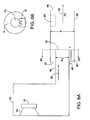
- FIG. 8 there is shown a diagrammatic representation of a loudspeaker enclosure 61 having a driver 62 and a port tube 63 formed with a vent 64 typically located at a point along the length of port tube 63 corresponding to the pressure maximum of the dominant standing wave established in port tube 63 when driver 62 is excited to reduce audible port noise.
- Acoustic damping material 90 for example, polyester or cloth, may be positioned in or near vent 64. This aspect of the invention reduces the objectionability of port noise caused by self resonances.
- the standing waves in the port tube generate the highest pressure midway between the ends of port tube 63.
- the acoustic damping material 90 may further reduce the Q of high frequency resonances.
- the leak can occur through vent 64 into the acoustic enclosure as shown in FIG. 8.
- the leak can leak into the space outside enclosure 61 through vent 64' of port tube 63' as shown in FIG. 9.
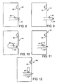
- the port tube 63" could leak through vent 64" to a different part of port tube 63" as shown in FIG. 10.
- Port tube 63"' could leak throug h vent 64"' into a small volume 65 as shown in FIG. 11.
- the port tube 63"" could leak through vent 64"" into a closed end resonant tube 65'.
- An advantage of the embodiments of FIGS. 11 and 12 is that the disclosed structure may have insignificant impact on the low frequency output.
- the acoustic damping material 90 may further reduce the Q of high frequency resonances.
- each may have dedicated closed end resonant tubes.
- vents may be used, including a slot, which can be considered as a series of contiguous vents.
- venting structures structures defining volumes for venting, including resonant closed end tubes.
- FIG. 13 there is shown a schematic representation of an embodiment of the invention for reducing Q of the half-wave resonance of a port tube 73 of length A1 in enclosure 71 having driver 72 using tube 75 with a closed end of length 0.3 A1 having its open end at vent 74.
- FIG. 13 there is shown a schematic representation of an embodiment of the invention for reducing Q of the half-wave resonance of a port tube 73 of length A1 in enclosure 71 having driver 72 using tube 75 with a closed end of length 0.3 A1 having its open end at vent 74.
- FIG. 14 shows the standing wave for the half-wave resonance along the length of tube 73, (in the absence of resonant tube 75), showing the pressure distribution 76 and volume velocity distribution 77.
- the pressure is at a maximum at point 74.
- Energy from the standing wave in the port tube 73 is removed from the port tube at maximum pressure point 74.
- the energy may be dissipated by damping material 90 in the resonant tube, significantly reducing the Q of the half-wave resonance.
- resonant tube 75 may be acoustic damping material.
- the acoustic damping material may fill only a small portion of the resonant tube 75 as indicated by acoustic damping material 90, or may substantially fill resonant tube as indicated in dotted line by acoustic damping material 90'.
- the acoustic damping material 90 or 90' reduces the Q of high frequency multiples of the half-wave resonant frequency.
- FIG. 15 there is shown a diagrammatic representation of a port tube 83 with a vent 84 six-tenths of the port tube length s from the left end and four-tenths of the port tube length from the right end terminated in a closed end resonant tube 85 of length 0.5 the length of port tube 83 and diameter d1 of 3" and another closed end tube 85' of length 0.25 that of port tube 83 and diameter d2 of 1.5".
- closed end resonant tube 85 and closed end resonant tube 85' may be acoustic damping material 90.
- the acoustic damping material may fill a portion of one or both of closed end resonant tubes 85, 85', or may substantially fill one or both of close end resonant tubes 85, 85'.
Abstract
Description
- The invention relates to porting and heat removal in acoustic devices, and more particularly to heat removal from ported acoustic enclosures.
It is an important object of the invention to provide an improved apparatus fo r porting. It is another object to remove undesired heat from an acoustic device. - According to an aspect of the invention, an electroacoustical device, comprises a loudspeaker enclosure including a first acoustic port, an acoustic driver mounted in the loudspeaker enclosure; and a heat producing device. The acoustic driver and the acoustic port are constructed and arranged to coact to provide a cooling, substantially unidirectional airflow across the heat producing device, thereby transferring heat from the heat producing device.
- In another aspect of the invention, an electroacoustical device includes an acoustic enclosure, a first acoustic port in the acoustic enclosure, an acoustic driver mounted in the acoustic enclosure for cau sing a first airflow in the port. The first airflow flows alternatingly inward and outward in the port. The device further includes a heat producing device. The acoustic port is constructed and arranged so that the first airflow creates a substantially unidirectional second airflow. The device also includes structure for causing the unidirectional airflow to flow across the heat producing device.
- In another aspect of the invention, a loudspeaker enclosure having an interior and an exterior includes a fi rst port having a first end having a cross-sectional area and a second end having a cross-sectional area, wherein the first end cross-sectional area is greater than the second end cross-sectional area. The first end abuts the interior, and the second end abuts the exterior. The enclosure also includes a second port. The first port is typically located below the second port.
- In another aspect of the invention, a loudspeaker includes an electroacoustical transducer and a loudspeaker enclosure. The loudspe aker enclosure has a first port having an interior end and an exterior end, each having cross-sectional area. The exterior end cross-sectional area is larger than the interior end cross-sectional area. The device also includes a second port having an interior end and an exterior end. The first port is typically located above the second port.
- In another aspect of the invention, a loudspeaker enclosure includes a first port having an interior end and an exterior end, each having a cross-sectional area. The first port interior end cross-sectional area is smaller than the first port exterior end cross-sectional area. The enclosure also includes a second port having an interior end and an exterior end, each end having a cross-sectional area. The second port interior end cross-sectional area is larger than the second port exterior end cross -sectional area.
- In another aspect of the invention, an electroacoustical device, for operating in an ambient environment includes an acoustic enclosure, comprising a port having an exit for radiating pressure waves; an electroacoustical transducer, positioned in the acoustic enclosure, for vibrating to produce the pressure waves; a second enclosure having a first opening and a second opening; wherein the port exit is positi oned near the first opening so that the pressure waves are radiated into the second enclosure through the first opening; a mounting position for a heat producing device in the first opening, positioned so that air flowing into the opening from the ambient environment flows across the mounting position.
- In another aspect of the invention, an electroacoustical device includes a first enclosure having a port having a terminal point for an outward airflow to exit the enclosure to an ambient environment and for an inward airflow to enter the enclosure. The device also includes an electroacoustical transducer, comprising a vibratile surface for generating pressure waves resulting in the outward airflow and the inward airflow. The device also includes a second en closure having a first opening and a second opening. The port terminal point is positioned near the first opening and oriented so that the port terminal outward flow flows toward the second opening. The port and the electroacoustical transducer coact to cause a substantially unidirectional airflow into the first opening.
- In another aspect of the invention, an electroacoustical device, for operating in an ambient environment includes an acoustic enclosure. The enclosure includes a port having an exit for radiating pressure waves. The electroacoustical device further includes an electroacoustical transducer, positioned in the acoustic enclosure, to provide the pressure waves. The device also includes an elongated second enclosure having a first extremity and a second extremity in a direction of elongation. There is a first opening at the first extremity and a second opening at the second extremity. The port exit is positioned in the first opening so that the pressure waves are radiated into the second enclosure through the first opening toward the second opening. The device also includes a mounting position for a heat producing device in the elongated second enclosure, positioned so that air flowing into the opening from the ambient environment flows across the mounting position.
- In still another aspect of the invention, an electroacoustical device includes a first enclosure having a port having a terminal point for an outward airflow to exit the enclosure and for an inward airflow to enter the enclosure. The device also includes an electroacoustical transducer, having a vibratile surface, mounted in the first enclosure, for generating pressure waves resulting in the outward airflow and the inward airflow. The device also includes a second enclosure havi ng a first opening and a second opening. The port terminal point is positioned with the port terminal point in the second enclosure, oriented so that the port terminal outward flow flows toward the second opening. The port and the electroacoustical transducer coact to cause a substantially unidirectional airflow into the first opening.
- According to an aspect of the invention, there is a loudspeaker enclosure having a loudspeaker driver and a port tube formed with a vent intermediate its ends constructed and arranged to introduce leakage resistance into the port tube that reduces the Q of at least one standing wave excited in the port tube when acoustic energy is transmitted therethrough. Venting may occur into the acoustic enclosure, into the space outside the enclosure, to a different part of the port tube, into a small volume, into a closed end resonant tube, or other suitable volume.
- Other features, objects, and advantages will become apparent from the following detailed description, when read in connection with the accompanying drawing in which:
-
- FIG. 1 is diagrammatic view of a prior art device;
- FIG. 2 is a diagrammatic view of a device according to the invention;
- FIGS. 3A and 3B are views of the device of FIG. 2, illustrating the workings of the device;
- FIGS. 4A - 41 are diagrammatic views of embodiments of the invention;
- FIG. 5 is a partial blowup of a loudspeaker incorporating the invention;
- FIGS. 6A and 6B are a diagram of another embodiment of the invention and a cross section viewed along line B - B, respectively;
- FIG. 7 is a diagrammatic view of an implementation of the embodiment of FIGS. 6A and 6B.
- FIG. 8 is a diagrammatic representation of a loudspeaker enclosure with a vented port tube according to the invention;
- FIG. 9 shows a form of the invention with the port tube vented outside the enclosure;
- FIG. 10 shows a form of the invention with the port tube vented to another portion of the port tube;
- FIG. 11 shows a form of the invention with the port tube vented into a small volume;
- FIGS. 12 and 13 show forms of the invention with the port tube vented into a closed end resonant tube;
- FIG. 14 shows standing wave patterns in the port tube; and
- FIG. 15 shows a form of the invention with the vent asymmetrically located and loaded by closed end tubes of different lengths.
-
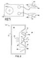
- With reference now to the drawing and more particularly to FIG. 1, there is shown a cross section of a prior art loudspeaker. A
loudspeaker 110 includes anenclosure 112 and anacoustic driver 114. In theenclosure 110 are twoports port 118 is positioned above the other.Ports upper port 118 is flared inwardly, that is, theinterior end 118i has a larger cross-sectional area than theexterior end 118e. The lower port is flared outwardly, that is, theexterior end 116e has a larger cross-sectional area than theinterior end 116i. - Referring now to FIG. 2, there is shown a cross sectional view of a loudspeaker according to the invention.
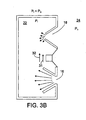
Loudspeaker 10 includes anenclosure 12 and anacoustic driver 14 having amotor structure 15. In the enclosure are two ports, 16 and 18, positioned so that oneport 16 is positioned lower in theenclosure 12 than theother port 18.Lower port 16 is flared inwardly, that is,interior end 16i has a larger cross -sectional area than theexterior end 16e.Upper port 18 is flared outwardly, that is,exterior end 18e has a larger cross-sectional area than theinterior end 18i. For purposes of illustration and explanation, the flares ofport motor structure 15 of the acoustic driver, or an optionalheat producing device 20, such as a power supply or amplifier forloudspeaker 10 or for another loudspeaker, not shown, or both. Optionalheat producing device 20 may be positioned lower thanupper port 18 for better results. It may be advantageous to remove heat frommotor structure 15, positioning it lower thanupper port 18 for better results. - In operation, a surface, such as
cone 13, ofacoustic driver 14 is driven bymotor structure 15 so that thecone 13 vibrates in the direction indicated byarrow 17, radiating sound waves, in this case to theexterior 24 of the enclosure and the interior 22 of the enclosure. In driving the acoustic driver cone, themotor structure 15 generates heat that is introduced intoenclosure interior 22. Sound waves radiated to the interior 22 of the enclosure result in sound waves radiated out throughports arrow 26. The DC airflow is described in more detail below. The DC airflow transfers heat away frommotor structure 15 and optionalheat producing element 20 throughupper port 18 and out of the enclosure, thereby cooling themotor structure 15 and the optionalheat producing element 20. - Referring to FIGS. 3a and 3b, the loudspeaker of FIG. 2 is shown to explain the DC airflow of FIG. 2. As the
loudspeaker 10 operates, the air pressure Pi inside the enclosure alternately increases and decreases relative to the pressure Po of the air outside the enclosure. When the pressure Pi is greater than pressure Po, as in FIG. 3a, the pressure differential urges the air to flow from the interior 22 to theexterior 24 of the enclosure. When the Pi pressure is less than the pressure Po, as in FIG. 3b, the pressure differential urges the air to flow from the exterior 24 to the interior 22. For a given magnitude of pressure across the port, there is more flow if the higher pressure end is the smaller end than if the higher pressure end is the larger end. When the airflow is from the interior to the exterior, as in FIG. 3a, there is more airflow through outwardly flaringport 18 than through inwardly flaringport 16, and there is anet DC airflow 31 toward outwardly flaringport 18, in the same direction asconvective airflow 32. When the airflow is from the exterior to the interior, as in FIG. 3b, there is more airflow through inwardly flaringport 16 than through outwardly flaringport 18, and there is anet DC airflow 31 away from inwardly flaringport 16 toward outwardly flaringport 18. Whether Pi pressure is less than or greater than the pressure Po, there is a net DC airflow in the same direction. Therefore, as interior pressure Pi cycles above and below Po, during normal operation ofloudspeaker 10, there is a DC airflow flowing in the same direction as theconvective DC airflow 32, and the DC airflow can be used to transfer heat from the interior of theenclosure 24 to the surrounding environment. - A loudspeaker according to the invention is advantageous because there is a port-induced airflow that is in the same direction as the convective airflow, increasing the cooling efficiency.
- Empirical results indicate that thermal rise of a test setup using the configuration of FIG. 1 was reduced by about 21% as compared to the thermal rise with no signal to the
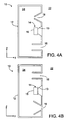
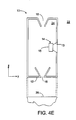
acoustic driver 114. With the configuration of FIG. 2, the thermal rise was reduced by about 75% as compared to the thermal rise with no signal toacoustic driver 14. - Referring to FIGS. 4A - 4I, several embodiments of the invention are shown. In FIG. 4A,
lower port 16 is a straight walled port, and the upper port is flared outwardly. In FIG. 4B,upper port 18 is a straight walled port, and the lower port is flared inwardly. The embodiments of FIGS. 4A and 4B have an airflow similar to the airflow of the embodiment of FIGS. 2 and 3, but the airflow is not as pronounced. In FIG. 4C, it is shown that theports enclosure 12; if the enclosure has curved sides, theports acoustic driver 14 and the twoports acoustic driver 14 and alternate locations shown in dashed lines, and the position ofports acoustic driver 14 need not be equidistant fromports ports upper port 18 is in the upper surface, facing upward, and the inwardly flaringlower port 16 is in the lower surface. If thelower port 16 is in the lower surface as in FIG. 4E, the enclosure wo uld typically have legs or some other spacing structure to spacelower port 16 fromsurface 28 on whichloudspeaker 10 rests. FIG. 4F shows that the port walls need not diverge linearly, and that the walls, in cross section, need not be straight lines. The embodiment of FIG. 4G shows that the divergence need not be monotonic, but can be flared both inwardly and outwardly, so long as the cross sectional area at theexterior end 18e of theupper port 18 is larger than the cross sectional area at theinterior end 18i, or so long as the cross sectional area at theexterior end 16e of thelower port 16 is smaller than the cross sectional area at theinterior end 16i, or both. Flaring a port in both directions may have acoustic advantages over straight walled ports or ports flared monotonically. In FIGS. 4H and 4I, the invention is incorporated in loudspeakers with more complex port and chamber structures, and with an acoustic driver that does not radiate directly to the exterior environment.Third port 117 of FIG. 5 is used for acoustic purposes. The operation of the embodiments of FIGS. 4H and 4I causes interior pressure Pi to cycle above and below exterior pressure Po, resulting in a net DC airflow as in the other embodiments, even thoughacoustic driver 14 does not radiate sound waves directly to the exterior of the enclosure. Aspects of the embodiments of FIGS. 4A - 4I can be combined. FIGS. 4A - 4I illustrate some of the many ways in which the invention may be implemented, not to show all the possible embodiments of the invention. In all the embodiments of FIGS. 4A - 4I, there are an upper port and a lower port, and either the upper port has a net outward flare, or the lower port has a net inward flare, or both. - Referring now to FIG. 5, there is shown a partially transparent view of a loudspeaker incorporating the invention. The cover 30 of the unit is removed to show internal detail of the loudspeaker. The embodiment of FIG. 5 is in the form of FIG. 4I. The reference numerals identify the elements of FIG. 5 that correspond to the like-numbered elements of FIG. 4I. Acoustic driver 14 (not shown in this view) is mounted in
cavity 32.Openings 19 help reduce standing waves in the port tube as described below. The variations in the cross sectional areas ofports ports 
- Referring to FIGS. 6A and 6B, there are shown two diagrammatic views of another embodiment of the invention. In FIG. 6A, ported
loudspeaker 10 has aport 40 that has aport exit 35 insideairflow passage 38. In oneconfiguration port 40 andairflow passage 38 are both pipe-like structures with one dimension long relative to the other dimensions, and with openings at the two lengthwise ends;port exit 35 has a cross-sectional area As smaller than the cross-sectional area A of theairflow passage 38; andport exit 35 is positioned in the airflow passage so that the longitudinal axes are parallel or coincident. Some considerations for the shape, dimensions, and placement ofport 40,port exit 35, andairflow passage 38 are presented below. Positioned insideairflow passage 38 isheat producing device 20 or 20', shown at two locations. In an actual implementation, the heat producing device or devices can be placed at many other locations inairflow passage 38. - When
acoustic driver 14 operates, it induces an airflow in and out of theport 40. When the airflow induced by the operation of the acoustic driver is in thedirection 36 out of theport 40, as shown in FIG. 6A, the port and airflow pa ssage act as a jet pump, which causes airflow in theairflow passage 38 in the same direction as the airflow out of the port, in this example inairflow passage opening 42, through the airflow passage indirection 45 and outairflow passage opening 44. Jet pumps are described generally in documents such as at the internet location
http://www.mas.ncl.ac.uk/~sbrooks/book/nish.mit.edu/2006/Textbook/Nodes/cha p05/node16.html. - Referring to FIG. 6B, when the acoustic driver induced airflow is in the direction 37 into
port 40, there is no jet pump effect. The airflow into theport 40 comes from all directions, including inwardly through airflow passageopen ing 42. Since the airflow comes from all directions, there is little net airflow within the airflow passage. - To summarize, when the acoustic driver induced airflow is in
direction 36, there is a jet pump effect that causes an airflow in airflowpassage op ening 42 and outpassage opening 44. When the acoustic driver induced airflow is in the direction 37, there is little net airflow inairflow passage 38. The net result of the operation of the acoustic driver is a net DC airflow indirection 45. The net DC airflow can be used to transfer heat away from heat producing elements, such asdevices 20 and 20', that are placed in the airflow path. - There are several considerations that are desirable to consider in determining the dimensions, shape, and positioning of
port 40 andairflow passage 38. The combined acoustic effect ofport 40 andpassage 38 is preferably in accordance with desired acoustic properties. It may be desirable to arrangeport 40 to have the desired acoustic property andairflow passage 38 to have significantly less acoustic effect while maintaining the momentum of the airflow in desireddirection 45 and to deter momentum in directions transverse to the desired direction. To thisend port 40 may be relatively elongated and with a straight axis of elongation parallel to the desired momentum direction. It may be desirable to structureairflow passage 38 to increase the proportion of the airflow is laminar and decrease the proportion of the airflow that is turbulent while providing a desired amount of airflow. - Referring to FIG. 7, there is shown a mechanical schematic drawing of an actual test implementation of the embodiment of FIGS. 6A and 6B, the elements numbered similarly to the corresponding elements of FIGS. 6A and 6B. In the test imple mentation device the
airflow passage 38 and the heat producing device were both parts of a unitary structure. A resistor was placed in thermal contact with at heat sink in a tubular form with appropriate dimensions so it could function as theairflow pass age 38. With current flowing through the resistor and withacoustic driver 14 not operating, the temperature in the vicinity of the heatsink rose 47° C. With the acoustic driver operating at 1/8 power, the temperature in the vicinity of the heatsink rose 39° C. With the acoustic driver operating at 1/3 power radiating pink noise, the temperature in the vicinity of the heatsink rose 25° C. Additionally, the thermal effect of the device at other points in the loudspeaker enclosure was measured. For example, atarea 55, convection heating caused the temperature to rise 30.5° C with current flowing through the resistor and withacoustic driver 14 not operating. With the acoustic driver operating at 1/3 power, the temperature in the vicinity of the heatsink rose 30.5° C. With the acoustic driver operating at 1/8 power radiating pink noise, the temperature in the vicinity of the heatsink rose 30.5° C. With the acoustic driver operating at 1/3 power radiating pink noise, the temperature in the vicinity of the heatsink rose 21° C. This indicates that if the acoustic driver operates at high enough power, thereby moving more air than when it operates at lower power, the airflow resulting from a loudspeaker according to the invention transfers heat from areas near, but not directly in, the airflow.
Referring to FIG. 8, there is shown a diagrammatic representation of aloudspeaker enclosure 61 having adriver 62 and aport tube 63 formed with avent 64 typically located at a point along the length ofport tube 63 corresponding to the pressure maximum of the dominant standing wave established inport tube 63 whendriver 62 is excited to reduce audible port noise. Acoustic dampingmaterial 90, for example, polyester or cloth, may be positioned in ornear vent 64.
This aspect of the invention reduces the objectionability of port noise caused by self resonances. For example, consider the case of increased noise at the frequency for which one-half wavelength is equal to the port length. In this example of self resonan ce, the standing waves in the port tube generate the highest pressure midway between the ends ofport tube 63. By establishing a small resistive leak near this point withvent 64 in the side of the tube, the Q of the resonance is significantly diminished to significantly reduce the objectionability of port noise at this frequency. The acoustic dampingmaterial 90 may further reduce the Q of high frequency resonances.
The leak can occur throughvent 64 into the acoustic enclosure as shown in FIG. 8. Alternatively, the leak can leak into the space outsideenclosure 61 through vent 64' of port tube 63' as shown in FIG. 9. Theport tube 63" could leak throughvent 64" to a different part ofport tube 63" as shown in FIG. 10.Port tube 63"' could leak through vent 64"' into a small volume 65 as shown in FIG. 11. Theport tube 63"" could leak throughvent 64"" into a closed end resonant tube 65'. In the embodiments of FIGS. 9 -12, there may be positioned near the vent 64' - 64"" acoustic dampingmaterial 90.
An advantage of the embodiments of FIGS. 11 and 12 is that the disclosed structure may have insignificant impact on the low frequency output. The acoustic dampingmaterial 90 may further reduce the Q of high frequency resonances.
The structures shown in FIGS. 9-12 reduce the Q of the self resonance corresponding to the half-wave resonance of the port tube. The principles of the invention may be applied to reducing the Q at other frequencies corresponding to the wavelength resonance, 3/2 wavelength resonan ce and other resonances. To reduce the Q at these different resonances, it may be desirable to establish vents at points other than midway between the ends of the port tubes. For example, consider the wavelength resonance where pressure peaks at a quarte r of the tube length from each end. A vent at these locations is more effective at diminishing the Q of the wavelength resonance than a vent at the midpoint of the tube. Vents at these points and other points may furnish leakage flow to the same small volume for the midpoint vent. Alternatively, each may have dedicated closed end resonant tubes. Still alternatively, they may allow leakage to the inside or outside of the enclosure. To reduce the audible output at a variety of resonances, a multiplicity of vents may be used, including a slot, which can be considered as a series of contiguous vents.
There are numerous combinations of venting structures, structures defining volumes for venting, including resonant closed end tubes.
Referring to FIG. 13, there is shown a schematic representation of an embodiment of the invention for reducing Q of the half-wave resonance of aport tube 73 of length A1 inenclosure 71 havingdriver 72 usingtube 75 with a closed end of length 0.3 A1 having its open end atvent 74. FIG. 14 shows the standing wave for the half-wave resonance along the length oftube 73, (in the absence of resonant tube 75), showing thepressure distribution 76 andvolume velocity distribution 77. The pressure is at a maximum atpoint 74. Energy from the standing wave in theport tube 73 is removed from the port tube atmaximum pressure point 74. The energy may be dissipated by dampingmaterial 90 in the resonant tube, significantly reducing the Q of the half-wave resonance. - In the
resonant tube 75 may be acoustic damping material. The acoustic damping material may fill only a small portion of theresonant tube 75 as indicated by acoustic dampingmaterial 90, or may substantially fill resonant tube as indicated in dotted line by acoustic damping material 90'. The acoustic dampingmaterial 90 or 90' reduces the Q of high frequency multiples of the half-wave resonant frequency. - Referring to FIG. 15, there is shown a diagrammatic representation of a
port tube 83 with avent 84 six-tenths of the port tube length s from the left end and four-tenths of the port tube length from the right end terminated in a closed endresonant tube 85 of length 0.5 the length ofport tube 83 and diameter d1 of 3" and another closed end tube 85' of length 0.25 that ofport tube 83 and diameter d2 of 1.5". In one or both of closed endresonant tube 85 and closed end resonant tube 85' may be acoustic dampingmaterial 90. As with the embodiment of FIG. 13, the acoustic damping material may fill a portion of one or both of closed endresonant tubes 85, 85', or may substantially fill one or both of close endresonant tubes 85, 85'. - It is evident that those skilled in the art may now make numerous uses and modifications of and departures from the specific apparatus and tech niques disclosed herein without departing from the inventive concepts. Consequently, the invention is to be construed as embracing each and every novel feature and novel combination of features present in or possessed by the apparatus and techniques disclosed herein and limited only by the scope of the appended claims.
Claims (26)
- An electroacoustical device comprising:a loudspeaker enclosure including a first acoustic port;an acoustic driver mounted in said loudspeaker enclosure;a heat producing device, heating surround air, and causing a convective airflow;said acoustic driver and said acoustic port constructed and arranged to coact to provide a cooling substantially unidirectional airflow in substantially the same direction as said convective airflow across said heat producing device thereby transferring heat from said heat producing device.
- An electroacoustical device in accordance with claim 1, wherein said loudspeaker enclosure further includes a second acoustic port,
said heat producing device positioned in said enclosure,
said first acoustic port, said second acoustic port, and said acoustic driver constructed and arranged to coact to provide a substantially unidirectional cooling airflow across said heat producing device, thereby transferring heat from said heat producing device. - An electroacoustical device in accordance with claim 1, and further comprising an airflow passage outside said loudspeaker enclosure,
said heat producing device positioned in said airflow passage. - An electroacoustical device comprising:an acoustic enclosure;a first acoustic port in said acoustic enclosure;an acoustic driver mounted in said acoustic enclosure for causing a first airflow in said first acoustic port,said first airflow alternatingly inward and outward of said enclosure;a heat producing device;
wherein said acoustic port is constructed and arranged so that said first airflow creates a substantially unidirectional second airflow; andstructure for directing said unidirectional second airflow across said heat producing device. - An electroacoustical device in accordance with claim 5 and further comprising:a second acoustic port constructed and arranged to coact with said first acoustic port to provide said second airflow.
- An electroacoustical device, in accordance with claim 5 and further comprising:an airflow passage outside said acoustic enclosure for directing said second airflow.
- A loudspeaker enclosure having an interior and an exterior, comprising:a first port having a first end having a cross-sectional area and a second end having a cross-sectional area,
wherein said first end cross sectional area is greater than said second end cross-sectional area with said first end abuts said interior and said second end abuts said exterior; anda second port located above said first port. - A loudspeaker enclosure in accordance with claim 7,
wherein said second port has a first end having a cross-sectional area and a second end having a cross-sectional area with said first end cross sectional area larger than said second end cross-sectional area, and wherein said second end abuts said interior and said first end abuts said exterior. - A loudspeaker enclosure in accordance with claim 7 and further comprising a mounting point for at least one heat producing device located below said second port.
- A loudspeaker enclosure in accordance with claim 9 wherein said mounting point is constructed and arranged for mounting an acoustic driver.
- A loudspeaker system comprising:an electroacoustical transducer;a loudspeaker enclosure having a first port having an interior end and an exterior end, said interior end and said exterior end each having cross-sectional area,wherein said exterior end cross-sectional area is larger than said interior end cross-sectional area; anda second port having an interior end and an exterior end, wherein said first port is located above said second port.
- A loudspeaker system in accordance with claim 11 wherein said second po rt interior end and said second port exterior end each has a cross-sectional area,
wherein said second port interior end cross-sectional area is larger than said second port exterior end cross-sectional area. - A loudspeaker system in accordance with claim 11, wherein said electroacoustical transducer is positioned in said loudspeaker enclosure higher than said first port and lower than said second port.
- A loudspeaker enclosure having a top and a bottom comprising:a first port having an interior end and an exterior end, each of said first port interior end and said first port exterior end having a cross -sectional area,
wherein said first port interior end cross-sectional area is smaller than said first port exterior end cross-sectional area;a second port having an interior end and an exterior end,each of said second port interior end and said second port exterior having a cross-sectional area,
wherein said second port interior cross-sectional area is larger than said second port external cross-sectional area. - A loudspeaker enclosure in accordance with claim 14, wherein said first port exterior cross-sectional area is positioned closer to said top than said second port interior cross-sectional area.
- A loudspeaker enclosure in accordance with claim 14 and further comprising an opening for an electroacoustical transducer positioned above said first port interior end and said second port interior end.
- An electroacoustical device for operating in an ambient environment comprising:an acoustic enclosure comprising a port having an exit for radiating pressure waves;an electroacoustical transducer positioned in said acoustic enclosure,said electroacoustical transducer for vibrating to produce said pressure waves;a second enclosure having a first opening and a second opening;
wherein said port exit is positioned near said first opening so that said pressure waves are radiated into said second enclosure through said first opening,
and wherein said port exit,said first opening, and said enclosure are constructed and arranged to cause air from said ambient environment to flow into said second enclosure through said first opening;a mounting position for a heat producing device in said second enclosure positioned so that air flowing into said second enclosure through first opening from said ambient environment flows across said mounting position. - An electroacoustical device in accordance with claim 17 and further comprising a heat producing element mounted at said mounting position.
- An electroacoustical device in accordance with claim 18 wherein said heat producing element is an audio amplifier.
- An electro-acoustical device, comprising:a first enclosure comprising a port having a terminal point for an outward airf low to exit said enclosure to an ambient environment and for an inward airflow to enter said enclosure;an electroacoustical transducer comprising a vibratile surface for generating pressure waves resulting in said outward airflow and said inward airflow;a second enclosure comprising a first opening and a second opening,
wherein the port terminal point is positioned near said first opening and oriented so that said port terminal outward flow flows toward said second opening and wherein said port and said electroacoustical transducer coact to cause a substantially unidirectional airflow to flow into said first opening. - An electroacoustical device for operating in an ambient environment comprising:an acoustic enclosure comprising a port having an exit for radiating pressure waves;an electroacoustical transducer positioned in said acoustic enclosure,said electroacoustical transducer for vibrating to provide said pressure waves;an elongated second enclosure having a first extremity and a second extremity in a direction of elongation;a first opening at said first extremity and a second opening at said second extremity;
wherein said port exit is positioned in said first opening so that said pressure waves are radiated into said second enclosure through said first opening toward said second opening; anda mounting position for a heat producing device in said elongated second enclosure positioned so that air flowing into said opening from said ambient environment flows across said mounting position. - An electroacoustical device in accordance with claim 21, further comprising a heat producing element mounted at said mounting position.
- An electroacoustical device in accordance with claim 22 wherein said heat producing element is an audio amplifier.
- An electroacoustical device, comprising:a first enclosure comprising a port having a terminal point for an outward airflow to exit said enclosure and for an inward airflow to enter said enclosure;an electroacoustical transducer comprising a vibratile surface mounted in said first enclosure for generating pressure waves resulting in said outward airflow and said inward airflow;a second enclosure comprising a first opening and a second opening,
wherein said port terminal point is positioned in said second enclosure and oriented so that said port terminal outward airflow flows toward said second opening and wherein said port and said electroacoustical transducer coact to cause a substantially unidirectional airflow into said first opening. - An electroacoustical device in accordance with claim 1 wherein said acoustic port is formed with a vent and further comprising,
an acoustic element communicating with said vent and coacting therewith to introduce damping acoustic impedance into sai d acoustic port that reduces the standing wave amplitude in said acoustic port for at least one predetermined wavelength. - A loudspeaker enclosure having a port tube, said port tube formed with a vent and further comprising,
an acoustic element communicating with said vent and coacting therewith to introduce damping acoustic impedance into said port that reduces the standing wave amplitude in said port for at least one predetermined wavelength, and;
acoustic damping material positioned in said acoustic element.
Applications Claiming Priority (2)
| Application Number | Priority Date | Filing Date | Title |
|---|---|---|---|
| US699304 | 1996-08-19 | ||
| US10/699,304 US7463744B2 (en) | 2003-10-31 | 2003-10-31 | Porting |
Publications (3)
| Publication Number | Publication Date |
|---|---|
| EP1528836A2 true EP1528836A2 (en) | 2005-05-04 |
| EP1528836A3 EP1528836A3 (en) | 2006-06-07 |
| EP1528836B1 EP1528836B1 (en) | 2010-01-20 |
Family
ID=34423443
Family Applications (1)
| Application Number | Title | Priority Date | Filing Date |
|---|---|---|---|
| EP20040105332 Expired - Fee Related EP1528836B1 (en) | 2003-10-31 | 2004-10-27 | Porting and heat removal in acoustic devices |
Country Status (6)
| Country | Link |
|---|---|
| US (4) | US7463744B2 (en) |
| EP (1) | EP1528836B1 (en) |
| JP (1) | JP4874536B2 (en) |
| CN (1) | CN1617629B (en) |
| DE (1) | DE602004025187D1 (en) |
| HK (1) | HK1078231A1 (en) |
Cited By (8)
| Publication number | Priority date | Publication date | Assignee | Title |
|---|---|---|---|---|
| EP1996006A3 (en) * | 2007-05-23 | 2010-04-07 | Funai Electric Co., Ltd. | Apparatus with a built-in loud speaker and LCD television receiver |
| FR2955731A1 (en) * | 2010-01-22 | 2011-07-29 | Canon Kk | Acoustic enclosure for emitting acoustic waves, has viscoelastic membrane displaced under action of wavy excitation to attenuate stationary acoustic wave created by cavity, at or around resonance frequency |
| EP2698538A3 (en) * | 2012-08-15 | 2014-06-18 | General Electric Company | Multi-function synthetic jet and method of manufacturing same |
| US9716940B2 (en) | 2013-03-22 | 2017-07-25 | Flare Audio Technologies Limited | Acoustic device |
| WO2018144389A1 (en) * | 2017-01-31 | 2018-08-09 | Sonos, Inc. | Noise reduction for high-airflow audio transducers |
| EP3383059A1 (en) * | 2017-03-27 | 2018-10-03 | Vestel Elektronik Sanayi ve Ticaret A.S. | Consumer electronic device and method for operating a consumer electronic device |
| CN108702562A (en) * | 2015-12-28 | 2018-10-23 | 伯斯有限公司 | Port energy converter enclosing element with acoustic resistors element |
| GB2559476B (en) * | 2016-12-30 | 2020-09-16 | Google Llc | Design for compact home assistant with combined acoustic waveguide and heat sink |
Families Citing this family (40)
| Publication number | Priority date | Publication date | Assignee | Title |
|---|---|---|---|---|
| US10842677B2 (en) * | 1996-03-11 | 2020-11-24 | Horst Burghardt Minkofski | Sound baffling device and material |
| US7463744B2 (en) * | 2003-10-31 | 2008-12-09 | Bose Corporation | Porting |
| US7565948B2 (en) * | 2004-03-19 | 2009-07-28 | Bose Corporation | Acoustic waveguiding |
| US7584820B2 (en) * | 2004-03-19 | 2009-09-08 | Bose Corporation | Acoustic radiating |
| US8103035B2 (en) | 2006-12-22 | 2012-01-24 | Bose Corporation | Portable audio system having waveguide structure |
| US7689197B2 (en) * | 2006-12-22 | 2010-03-30 | Bose Corporation | Portable audio system with docking cradle |
| JP5128919B2 (en) * | 2007-11-30 | 2013-01-23 | 船井電機株式会社 | Microphone unit and voice input device |
| JP2009290346A (en) * | 2008-05-27 | 2009-12-10 | Panasonic Electric Works Co Ltd | Panel speaker apparatus |
| DE102009046889A1 (en) * | 2009-11-19 | 2011-07-21 | K+H Vertriebs- und Entwicklungsgesellschaft mbH, 30900 | Loudspeaker unit |
| CN102143418B (en) * | 2011-02-18 | 2014-11-05 | 徐新国 | Air convection type phase reversal sound box |
| US8744108B2 (en) | 2011-07-12 | 2014-06-03 | Strata Audio LLC | Balanced momentum inertial duct |
| US8561756B2 (en) | 2012-02-17 | 2013-10-22 | Bose Corporation | Acoustic ports aligned to create free convective airflow |
| US8798308B2 (en) | 2012-02-21 | 2014-08-05 | Bose Corporation | Convective airflow using a passive radiator |
| US9173018B2 (en) | 2012-06-27 | 2015-10-27 | Bose Corporation | Acoustic filter |
| CN103220608B (en) * | 2013-04-16 | 2016-08-24 | 歌尔声学股份有限公司 | Speaker module |
| US9301043B2 (en) * | 2013-05-01 | 2016-03-29 | Harman International Industries, Inc. | Sealed speaker system having a pressure vent |
| TWI531248B (en) * | 2013-08-23 | 2016-04-21 | 宏碁股份有限公司 | Sound box structure |
| US20160037253A1 (en) * | 2014-07-30 | 2016-02-04 | Goal Zero Llc | Portable speaker system |
| US9860660B1 (en) | 2014-09-30 | 2018-01-02 | Apple Inc. | Electronic device with speaker cavity cooling |
| US10045461B1 (en) * | 2014-09-30 | 2018-08-07 | Apple Inc. | Electronic device with diaphragm cooling |
| US10631093B2 (en) * | 2015-01-26 | 2020-04-21 | Harman International Industries, Incorporated | Vented loudspeaker system with duct for cooling of internal components |
| US9571935B2 (en) | 2015-01-26 | 2017-02-14 | Harman International Industries, Inc. | Loudspeaker with ducts for transducer voice coil cooling |
| US10701491B2 (en) * | 2015-12-17 | 2020-06-30 | Eric Jay Alexander | Fluid diode loudspeaker |
| US9906855B2 (en) * | 2015-12-28 | 2018-02-27 | Bose Corporation | Reducing ported transducer array enclosure noise |
| US10123111B2 (en) * | 2016-06-03 | 2018-11-06 | Fulcrum Acoustic, LLC | Passive cardioid speaker |
| CN106792335B (en) * | 2017-01-05 | 2019-09-06 | 联想(北京)有限公司 | A kind of electronic equipment |
| JP6641644B2 (en) * | 2017-02-15 | 2020-02-05 | カシオ計算機株式会社 | Speaker box and projection device |
| US10438868B2 (en) * | 2017-02-20 | 2019-10-08 | Microjet Technology Co., Ltd. | Air-cooling heat dissipation device |
| US11148048B2 (en) * | 2017-03-07 | 2021-10-19 | Sony Corporation | Content presentation system, content presentation device, and wind presenting device |
| US10306356B2 (en) | 2017-03-31 | 2019-05-28 | Bose Corporation | Acoustic deflector as heat sink |
| USD872054S1 (en) | 2017-08-04 | 2020-01-07 | Bose Corporation | Speaker |
| JP6277314B1 (en) * | 2017-08-07 | 2018-02-07 | 勝巳 瀬戸 | Speaker device |
| US10393155B2 (en) * | 2017-08-21 | 2019-08-27 | Out of the Box Audio, LLC | Methods and apparatus for improving sound within an acoustical boundary layer |
| US10425739B2 (en) * | 2017-10-03 | 2019-09-24 | Bose Corporation | Acoustic deflector with convective cooling |
| US20190253806A1 (en) | 2018-02-15 | 2019-08-15 | Alexander B. RALPH | Ported tweeter |
| DE102019108423B4 (en) * | 2019-04-01 | 2021-08-05 | Svetlomir Aleksandrov | Loudspeaker box and loudspeaker |
| US11540417B2 (en) * | 2019-08-14 | 2022-12-27 | AAC Technologies Pte. Ltd. | Sounding device and mobile terminal |
| US11310587B2 (en) | 2019-10-08 | 2022-04-19 | Bose Corporation | Horn loudspeakers |
| JP6857271B1 (en) * | 2019-10-14 | 2021-04-14 | シャープ株式会社 | Speaker device and display device |
| US11917361B2 (en) * | 2020-08-12 | 2024-02-27 | Michael Levy | Loudspeaker |
Citations (2)
| Publication number | Priority date | Publication date | Assignee | Title |
|---|---|---|---|---|
| JPS61219289A (en) | 1985-03-25 | 1986-09-29 | Matsushita Electric Ind Co Ltd | Speaker system with amplifier |
| JP2001346283A (en) | 2000-06-01 | 2001-12-14 | Matsushita Electric Ind Co Ltd | Loudspeaker system |
Family Cites Families (64)
| Publication number | Priority date | Publication date | Assignee | Title |
|---|---|---|---|---|
| US3393766A (en) | 1966-05-18 | 1968-07-23 | American District Telegraph Co | Speaker system |
| US3517390A (en) * | 1968-02-29 | 1970-06-23 | Layne Whitehead | High power acoustic radiator |
| GB1487847A (en) | 1974-09-25 | 1977-10-05 | Ard Anstalt | Microphone units |
| JPS5333613A (en) | 1976-09-09 | 1978-03-29 | Matsushita Electric Ind Co Ltd | Microphone and its manufacture |
| US4146744A (en) | 1976-09-02 | 1979-03-27 | Bose Corporation | Low q multiple in phase high compliance driver ported loudspeaker enclosure |
| JPS6013167Y2 (en) | 1977-09-07 | 1985-04-26 | 株式会社日立製作所 | magnetron |
| JPS55152766A (en) * | 1979-05-17 | 1980-11-28 | Canon Inc | Recording liquid |
| US4307825A (en) | 1979-09-24 | 1981-12-29 | Pattermann Norbert C | Bricklayers trowel holster |
| DE3025569A1 (en) | 1980-07-05 | 1982-02-04 | Klaus 4400 Münster Burhans | Water jet pump for chemical use - has adaptor to utilise part of pumping flow for cooling other equipment |
| JPS57131069A (en) * | 1981-02-06 | 1982-08-13 | Matsushita Electric Works Ltd | Circuit for detecting voltage variation |
| US4906864A (en) | 1984-10-01 | 1990-03-06 | United Technologies Corporation | Linear slope peak detector |
| JPS62143841A (en) | 1985-12-16 | 1987-06-27 | Nippon Sheet Glass Co Ltd | Chalcogenide glass |
| JPS6374297A (en) | 1986-09-17 | 1988-04-04 | Mitsubishi Electric Corp | Speaker system |
| US4802227A (en) | 1987-04-03 | 1989-01-31 | American Telephone And Telegraph Company | Noise reduction processing arrangement for microphone arrays |
| US4811403A (en) * | 1987-06-10 | 1989-03-07 | U.S. Sound, Inc. | Ultralight loudspeaker enclosures |
| JPH01149192A (en) * | 1987-12-07 | 1989-06-12 | Toshiba Corp | Showcase/vending machine |
| US5012890A (en) * | 1988-03-23 | 1991-05-07 | Yamaha Corporation | Acoustic apparatus |
| JPH01241296A (en) | 1988-03-23 | 1989-09-26 | Yamaha Corp | Acoustic equipment |
| JPH01241297A (en) | 1988-03-23 | 1989-09-26 | Yamaha Corp | Acoustic equipment |
| EP0334238B1 (en) | 1988-03-25 | 1994-11-30 | Yamaha Corporation | Acoustic Apparatus |
| EP0336303A3 (en) | 1988-04-04 | 1991-05-15 | Yamaha Corporation | Acoustic apparatus |
| US4875546A (en) * | 1988-06-02 | 1989-10-24 | Teledyne Industries, Inc. | Loudspeaker with acoustic band-pass filter |
| EP0361445A3 (en) * | 1988-09-28 | 1991-05-22 | Yamaha Corporation | Acoustic apparatus |
| US4903300A (en) * | 1989-01-05 | 1990-02-20 | Polk Investment Corporation | Compact and efficient sub-woofer system and method for installation in structural partitions |
| US5150471A (en) * | 1989-04-20 | 1992-09-22 | Ncr Corporation | Method and apparatus for offset register address accessing |
| NL8902831A (en) * | 1989-11-16 | 1991-06-17 | Philips Nv | SPEAKER SYSTEM CONTAINING A HELMHOLTZ RESONATOR COUPLED WITH AN ACOUSTIC TUBE. |
| JP3186049B2 (en) * | 1990-03-13 | 2001-07-11 | 松下電器産業株式会社 | Speaker device |
| US5275693A (en) | 1990-03-30 | 1994-01-04 | Yamato Kako Kabushiki Kaisha | Film forming process |
| US5005744A (en) | 1990-08-03 | 1991-04-09 | Gleason Dana W | Adjustable backpack |
| US5150417A (en) | 1991-02-25 | 1992-09-22 | Socon Ab | Bass reflex type speaker system |
| US5357586A (en) * | 1991-05-16 | 1994-10-18 | The Nordschow/Wright Loudspeaker Company | Flow-through air-cooled loudspeaker system |
| EP0529169A1 (en) * | 1991-08-29 | 1993-03-03 | International Business Machines Corporation | Apparatus for connecting a communicating equipment to a digital communication network having at least two digital communication channels |
| JP3279612B2 (en) | 1991-12-06 | 2002-04-30 | ソニー株式会社 | Noise reduction device |
| US5740259A (en) | 1992-06-04 | 1998-04-14 | Bose Corporation | Pressure wave transducing |
| EP0589515B1 (en) * | 1992-09-23 | 1999-01-27 | Koninklijke Philips Electronics N.V. | Loudspeaker system comprising a plurality of tubes |
| US5373564A (en) | 1992-10-02 | 1994-12-13 | Spear; Robert J. | Transmission line for planar waves |
| JPH06167982A (en) | 1992-11-30 | 1994-06-14 | Mitsubishi Electric Corp | Sound absorbing duct formed by using porous sound absorbing material |
| JPH06245286A (en) * | 1993-02-19 | 1994-09-02 | Sony Corp | Speaker |
| US6278789B1 (en) | 1993-05-06 | 2001-08-21 | Bose Corporation | Frequency selective acoustic waveguide damping |
| US5589799A (en) | 1994-09-29 | 1996-12-31 | Tibbetts Industries, Inc. | Low noise amplifier for microphone |
| JPH08140177A (en) | 1994-11-14 | 1996-05-31 | Matsushita Electric Ind Co Ltd | Speaker system |
| GB2295518B (en) * | 1994-12-23 | 1998-08-05 | Graeme John Huon | Loudspeaker system incorporating acoustic waveguide filters and method of construction |
| US5533132A (en) * | 1995-01-23 | 1996-07-02 | Jbl Incorporated | Loudspeaker thermal management structure |
| IL117666A0 (en) | 1995-03-31 | 1996-07-23 | Bsg Lab Inc | Low frequency audio coupler and method of coupling |
| US5673330A (en) | 1995-11-08 | 1997-09-30 | Chang; Ching-Lu | Microphone transducer with noise reducing member |
| US6009184A (en) | 1996-10-08 | 1999-12-28 | Umevoice, Inc. | Noise control device for a boom mounted noise-canceling microphone |
| JPH10148181A (en) * | 1996-11-19 | 1998-06-02 | Shinten Sangyo Kk | Air pump |
| US5792999A (en) * | 1997-01-23 | 1998-08-11 | Bose Corporation | Noise attenuating in ported enclosure |
| US6275597B1 (en) * | 1998-05-27 | 2001-08-14 | U.S. Philips Corporation | Loudspeaker system having a bass-reflex port |
| US6549637B1 (en) * | 1998-09-24 | 2003-04-15 | Peavey Electronics Corp. | Loudspeaker with differential flow vent means |
| US6169811B1 (en) * | 1999-03-02 | 2001-01-02 | American Technology Corporation | Bandpass loudspeaker system |
| US7103193B2 (en) * | 2000-09-15 | 2006-09-05 | American Technology Corporation | Bandpass woofer enclosure with multiple acoustic fibers |
| US6549037B1 (en) * | 2000-06-26 | 2003-04-15 | Intel Corporation | Apparatus and circuit having reduced leakage current and method therefor |
| EP1334623A2 (en) | 2000-10-12 | 2003-08-13 | Reveo, Inc. | 3d projection system with a digital micromirror device |
| US7426280B2 (en) * | 2001-01-02 | 2008-09-16 | Bose Corporation | Electroacoustic waveguide transducing |
| EP1358766A1 (en) | 2001-01-12 | 2003-11-05 | Vrex Inc. | Method and apparatus for stereoscopic display using column interleaved data with digital light processing |
| US7711134B2 (en) * | 2001-06-25 | 2010-05-04 | Harman International Industries, Incorporated | Speaker port system for reducing boundary layer separation |
| JP4086622B2 (en) * | 2002-03-11 | 2008-05-14 | ローランド株式会社 | Speaker device |
| US7123736B2 (en) * | 2002-09-27 | 2006-10-17 | Sony Ericsson Mobile Communications Ab | Double-resonator micro-speaker assemblies and methods for tuning the same |
| JP2004285895A (en) | 2003-03-20 | 2004-10-14 | Toyoda Gosei Co Ltd | Intake device |
| US7463744B2 (en) * | 2003-10-31 | 2008-12-09 | Bose Corporation | Porting |
| US7584820B2 (en) | 2004-03-19 | 2009-09-08 | Bose Corporation | Acoustic radiating |
| JP2008131199A (en) | 2006-11-17 | 2008-06-05 | Pioneer Electronic Corp | Speaker system |
| US8351630B2 (en) | 2008-05-02 | 2013-01-08 | Bose Corporation | Passive directional acoustical radiating |
-
2003
- 2003-10-31 US US10/699,304 patent/US7463744B2/en active Active
-
2004
- 2004-10-27 EP EP20040105332 patent/EP1528836B1/en not_active Expired - Fee Related
- 2004-10-27 DE DE200460025187 patent/DE602004025187D1/en active Active
- 2004-10-29 JP JP2004315046A patent/JP4874536B2/en not_active Expired - Fee Related
- 2004-10-29 CN CN200410089636.4A patent/CN1617629B/en not_active Expired - Fee Related
-
2005
- 2005-11-09 HK HK05109993.3A patent/HK1078231A1/en not_active IP Right Cessation
-
2008
- 2008-10-09 US US12/248,326 patent/US20090041282A1/en not_active Abandoned
-
2009
- 2009-04-01 US US12/416,516 patent/US8107662B2/en not_active Expired - Fee Related
-
2011
- 2011-12-22 US US13/335,533 patent/US8831263B2/en not_active Expired - Lifetime
Patent Citations (2)
| Publication number | Priority date | Publication date | Assignee | Title |
|---|---|---|---|---|
| JPS61219289A (en) | 1985-03-25 | 1986-09-29 | Matsushita Electric Ind Co Ltd | Speaker system with amplifier |
| JP2001346283A (en) | 2000-06-01 | 2001-12-14 | Matsushita Electric Ind Co Ltd | Loudspeaker system |
Cited By (15)
| Publication number | Priority date | Publication date | Assignee | Title |
|---|---|---|---|---|
| EP1996006A3 (en) * | 2007-05-23 | 2010-04-07 | Funai Electric Co., Ltd. | Apparatus with a built-in loud speaker and LCD television receiver |
| US8077901B2 (en) | 2007-05-23 | 2011-12-13 | Funai Electric Co., Ltd. | Apparatus with a built-in loud speaker and LCD television receiver |
| FR2955731A1 (en) * | 2010-01-22 | 2011-07-29 | Canon Kk | Acoustic enclosure for emitting acoustic waves, has viscoelastic membrane displaced under action of wavy excitation to attenuate stationary acoustic wave created by cavity, at or around resonance frequency |
| US10165343B2 (en) | 2012-08-15 | 2018-12-25 | General Electric Company | Multi-function synthetic jet and method of manufacturing same |
| US9215520B2 (en) | 2012-08-15 | 2015-12-15 | General Electric Company | Multi-function synthetic jet and method of manufacturing same |
| EP2698538A3 (en) * | 2012-08-15 | 2014-06-18 | General Electric Company | Multi-function synthetic jet and method of manufacturing same |
| US9716940B2 (en) | 2013-03-22 | 2017-07-25 | Flare Audio Technologies Limited | Acoustic device |
| CN108702562A (en) * | 2015-12-28 | 2018-10-23 | 伯斯有限公司 | Port energy converter enclosing element with acoustic resistors element |
| CN108702562B (en) * | 2015-12-28 | 2019-10-18 | 伯斯有限公司 | Port energy converter enclosing element with acoustic resistors element |
| EP3398352B1 (en) * | 2015-12-28 | 2021-07-14 | Bose Corporation | Ported transducer enclosure with acoustic resistive elements |
| GB2559476B (en) * | 2016-12-30 | 2020-09-16 | Google Llc | Design for compact home assistant with combined acoustic waveguide and heat sink |
| WO2018144389A1 (en) * | 2017-01-31 | 2018-08-09 | Sonos, Inc. | Noise reduction for high-airflow audio transducers |
| CN110476439A (en) * | 2017-01-31 | 2019-11-19 | 搜诺思公司 | Noise reduction for high gas flow audio-frequency transducer |
| CN110476439B (en) * | 2017-01-31 | 2020-11-06 | 搜诺思公司 | Noise reduction for high airflow audio transducers |
| EP3383059A1 (en) * | 2017-03-27 | 2018-10-03 | Vestel Elektronik Sanayi ve Ticaret A.S. | Consumer electronic device and method for operating a consumer electronic device |
Also Published As
| Publication number | Publication date |
|---|---|
| CN1617629A (en) | 2005-05-18 |
| US20090245563A1 (en) | 2009-10-01 |
| US20090041282A1 (en) | 2009-02-12 |
| JP2005176316A (en) | 2005-06-30 |
| JP4874536B2 (en) | 2012-02-15 |
| US20120328141A1 (en) | 2012-12-27 |
| US7463744B2 (en) | 2008-12-09 |
| EP1528836B1 (en) | 2010-01-20 |
| US8831263B2 (en) | 2014-09-09 |
| EP1528836A3 (en) | 2006-06-07 |
| HK1078231A1 (en) | 2006-03-03 |
| US20050094837A1 (en) | 2005-05-05 |
| CN1617629B (en) | 2015-09-30 |
| US8107662B2 (en) | 2012-01-31 |
| DE602004025187D1 (en) | 2010-03-11 |
Similar Documents
| Publication | Publication Date | Title |
|---|---|---|
| EP1528836A2 (en) | Porting and heat removal in acoustic devices | |
| CN101405508B (en) | Cooling device and electronic device comprising such a cooling device | |
| US7793709B2 (en) | Jet generating device and electronic apparatus | |
| US8561756B2 (en) | Acoustic ports aligned to create free convective airflow | |
| US11381919B2 (en) | Speaker box and speaker | |
| WO2016000312A1 (en) | Speaker module | |
| WO2016000373A1 (en) | Sound producing device | |
| US20170055084A1 (en) | Inverted dual coil transducer | |
| CN111194558B (en) | Acoustic deflector with convective cooling | |
| JP2011512108A (en) | Waveguide electroacoustic conversion | |
| JP2007104526A (en) | Speaker system | |
| WO2019227924A1 (en) | Miniature loudspeaker module | |
| KR102023189B1 (en) | Sound generation apparatus and electric apparatus comprising thereof | |
| JPH0727750Y2 (en) | Audio equipment | |
| TW200934064A (en) | Low noise cooling device | |
| WO2017053714A1 (en) | Compact audio output electronic device with heat dissipation | |
| WO2021012233A1 (en) | Loudspeaker device and mobile terminal having same | |
| CN214592556U (en) | Mute radiator and electronic equipment | |
| EP4230873A1 (en) | Noise reduced blower means and their use in electric power tools and devices | |
| JPH0727751Y2 (en) | Audio equipment | |
| JP2000102082A (en) | Amplifier with built-in speaker | |
| JP2000004490A (en) | Speaker | |
| CN114268882A (en) | Electronic device with speaker module | |
| JPH09207U (en) | Sound equipment | |
| JPH07115696A (en) | Speaker device |
Legal Events
| Date | Code | Title | Description |
|---|---|---|---|
| PUAI | Public reference made under article 153(3) epc to a published international application that has entered the european phase |
Free format text: ORIGINAL CODE: 0009012 |
|
| AK | Designated contracting states |
Kind code of ref document: A2 Designated state(s): AT BE BG CH CY CZ DE DK EE ES FI FR GB GR HU IE IT LI LU MC NL PL PT RO SE SI SK TR |
|
| AX | Request for extension of the european patent |
Extension state: AL HR LT LV MK |
|
| PUAL | Search report despatched |
Free format text: ORIGINAL CODE: 0009013 |
|
| AK | Designated contracting states |
Kind code of ref document: A3 Designated state(s): AT BE BG CH CY CZ DE DK EE ES FI FR GB GR HU IE IT LI LU MC NL PL PT RO SE SI SK TR |
|
| AX | Request for extension of the european patent |
Extension state: AL HR LT LV MK |
|
| 17P | Request for examination filed |
Effective date: 20061201 |
|
| AKX | Designation fees paid |
Designated state(s): DE GB |
|
| 17Q | First examination report despatched |
Effective date: 20070618 |
|
| GRAP | Despatch of communication of intention to grant a patent |
Free format text: ORIGINAL CODE: EPIDOSNIGR1 |
|
| GRAS | Grant fee paid |
Free format text: ORIGINAL CODE: EPIDOSNIGR3 |
|
| GRAA | (expected) grant |
Free format text: ORIGINAL CODE: 0009210 |
|
| AK | Designated contracting states |
Kind code of ref document: B1 Designated state(s): DE GB |
|
| REG | Reference to a national code |
Ref country code: GB Ref legal event code: FG4D |
|
| REF | Corresponds to: |
Ref document number: 602004025187 Country of ref document: DE Date of ref document: 20100311 Kind code of ref document: P |
|
| PLBE | No opposition filed within time limit |
Free format text: ORIGINAL CODE: 0009261 |
|
| STAA | Information on the status of an ep patent application or granted ep patent |
Free format text: STATUS: NO OPPOSITION FILED WITHIN TIME LIMIT |
|
| 26N | No opposition filed |
Effective date: 20101021 |
|
| PGFP | Annual fee paid to national office [announced via postgrant information from national office to epo] |
Ref country code: GB Payment date: 20191028 Year of fee payment: 16 |
|
| PGFP | Annual fee paid to national office [announced via postgrant information from national office to epo] |
Ref country code: DE Payment date: 20201028 Year of fee payment: 17 |
|
| GBPC | Gb: european patent ceased through non-payment of renewal fee |
Effective date: 20201027 |
|
| PG25 | Lapsed in a contracting state [announced via postgrant information from national office to epo] |
Ref country code: GB Free format text: LAPSE BECAUSE OF NON-PAYMENT OF DUE FEES Effective date: 20201027 |
|
| REG | Reference to a national code |
Ref country code: DE Ref legal event code: R119 Ref document number: 602004025187 Country of ref document: DE |
|
| PG25 | Lapsed in a contracting state [announced via postgrant information from national office to epo] |
Ref country code: DE Free format text: LAPSE BECAUSE OF NON-PAYMENT OF DUE FEES Effective date: 20220503 |