EP1528757A1 - Scharniergelenk für ein tragbares Endgerät - Google Patents
Scharniergelenk für ein tragbares Endgerät Download PDFInfo
- Publication number
- EP1528757A1 EP1528757A1 EP04025770A EP04025770A EP1528757A1 EP 1528757 A1 EP1528757 A1 EP 1528757A1 EP 04025770 A EP04025770 A EP 04025770A EP 04025770 A EP04025770 A EP 04025770A EP 1528757 A1 EP1528757 A1 EP 1528757A1
- Authority
- EP
- European Patent Office
- Prior art keywords
- hinge
- housing
- cam
- stopper
- portable terminal
- Prior art date
- Legal status (The legal status is an assumption and is not a legal conclusion. Google has not performed a legal analysis and makes no representation as to the accuracy of the status listed.)
- Granted
Links
Images


Classifications
-
- H—ELECTRICITY
- H04—ELECTRIC COMMUNICATION TECHNIQUE
- H04M—TELEPHONIC COMMUNICATION
- H04M1/00—Substation equipment, e.g. for use by subscribers
- H04M1/02—Constructional features of telephone sets
- H04M1/0202—Portable telephone sets, e.g. cordless phones, mobile phones or bar type handsets
- H04M1/0206—Portable telephones comprising a plurality of mechanically joined movable body parts, e.g. hinged housings
- H04M1/0208—Portable telephones comprising a plurality of mechanically joined movable body parts, e.g. hinged housings characterized by the relative motions of the body parts
- H04M1/0225—Rotatable telephones, i.e. the body parts pivoting to an open position around an axis perpendicular to the plane they define in closed position
- H04M1/0227—Rotatable in one plane, i.e. using a one degree of freedom hinge
-
- H—ELECTRICITY
- H04—ELECTRIC COMMUNICATION TECHNIQUE
- H04B—TRANSMISSION
- H04B1/00—Details of transmission systems, not covered by a single one of groups H04B3/00 - H04B13/00; Details of transmission systems not characterised by the medium used for transmission
- H04B1/38—Transceivers, i.e. devices in which transmitter and receiver form a structural unit and in which at least one part is used for functions of transmitting and receiving
-
- H—ELECTRICITY
- H04—ELECTRIC COMMUNICATION TECHNIQUE
- H04M—TELEPHONIC COMMUNICATION
- H04M1/00—Substation equipment, e.g. for use by subscribers
- H04M1/02—Constructional features of telephone sets
- H04M1/0202—Portable telephone sets, e.g. cordless phones, mobile phones or bar type handsets
- H04M1/0206—Portable telephones comprising a plurality of mechanically joined movable body parts, e.g. hinged housings
- H04M1/0208—Portable telephones comprising a plurality of mechanically joined movable body parts, e.g. hinged housings characterized by the relative motions of the body parts
- H04M1/0225—Rotatable telephones, i.e. the body parts pivoting to an open position around an axis perpendicular to the plane they define in closed position
- H04M1/0227—Rotatable in one plane, i.e. using a one degree of freedom hinge
- H04M1/0229—The hinge comprising input and/or output user interface means
-
- H—ELECTRICITY
- H04—ELECTRIC COMMUNICATION TECHNIQUE
- H04M—TELEPHONIC COMMUNICATION
- H04M1/00—Substation equipment, e.g. for use by subscribers
- H04M1/02—Constructional features of telephone sets
- H04M1/0202—Portable telephone sets, e.g. cordless phones, mobile phones or bar type handsets
- H04M1/0206—Portable telephones comprising a plurality of mechanically joined movable body parts, e.g. hinged housings
- H04M1/0208—Portable telephones comprising a plurality of mechanically joined movable body parts, e.g. hinged housings characterized by the relative motions of the body parts
- H04M1/0225—Rotatable telephones, i.e. the body parts pivoting to an open position around an axis perpendicular to the plane they define in closed position
- H04M1/0233—Including a rotatable display body part
Definitions
- the present invention relates to a portable terminal. More particularly, the present invention relates to a swing hinge device for a portable terminal, which is adapted to couple a pair of housings to each other in such a manner that they can be rotated while facing each other.
- portable terminals are classified as bar-type terminals, flip-type terminals, or folder-type terminals according to their appearance.
- Bar-type terminals have a single housing on which data input and output means, as well as transmitter and receiver modules are positioned. However, they have a problem in that their keypad, which is used as the data input means, is always exposed and may be accidentally operated. In addition, there exists a limitation in reducing the size of bar-type terminals because a certain distance must be maintained between their transmitter and receiver modules.
- Flip-type terminals have a body, a flip, and a hinge means for connecting the body with the flip.
- the body has data input and output means, as well as transmitter and receiver modules positioned thereon.
- the flip is adapted to cover the keypad, which is used as the data input means, so that any accidental operation thereof can be avoided.
- there still exists a limitation in reducing the size of flip-type terminals because a distance must be maintained between their transmitter and receiver modules.
- the folder-type terminals have a body, a folder, and a hinge means for connecting the body with the folder in such a manner that the folder can be rotated to open and close the terminal.
- the body has a keypad, which is used as a data input means, and a transmitter module.
- the folder has a display device, which is used as a data output means, and a receiver module.
- a standby mode the folder is folded onto the body to avoid accidental erroneous operation of the keypad.
- the folder is unfolded to maintain a sufficient distance between the transmitter and receiver modules. This is beneficial for reducing the size of the folder-type terminals. For this reason, recent portable terminals are mostly configured as the folder-type terminals.
- sliding-type and swing-type terminals which can be opened and closed while a pair of housings thereof face each other.
- Terminals which combine the opening and closing operation of the folder-type terminals with that of the swing-type terminals, as well as a terminal having a folder which can be rotated, when it is opened, in a direction such that it is twisted relative to a body of the terminal have also been developed.
- an object of the present invention is to provide a swing hinge device of a portable terminal wherein the opening and closing operation of the terminal, which is opened and closed by rotating a pair of housings while they face each other, is implemented semi-automatically for convenient use.
- Another object of the present invention is to provide a swing hinge device of a portable terminal wherein the range of rotation of a housing, which is rotated while facing another housing, is limited to avoid any damage to a flexible printed circuit board and the like, which may be positioned between them.
- a swing hinge device of a portable terminal having a first housing, a second housing, and a swing hinge device for connecting the second housing with the first housing in such a manner that they can be rotated while facing each other.
- the device comprises a hinge housing extending along the longitudinal direction of the device and having an end, which is configured as an open end, and the other end, which is configured as a closed end.
- a hinge shaft is rotatably coupled in the hinge housing and protruding from the open end of the hinge housing.
- a first hinge cam is coupled in the hinge housing in such a manner that it can move linearly along the longitudinal direction and having a slant surface formed on its surface.
- a second hinge cam is fixedly coupled to an end of the hinge shaft in such a manner that it can be rotated in the hinge housing and having a slant surface corresponding to that of the first hinge cam.
- a resilient means is supported on the closed end of the hinge housing to provide the first hinge cam with a resilient force in a direction such that the first and second hinge cams are forced against each other.
- a hinge stopper is adapted to be rotated about the hinge shaft, along its side and together with it, and to be moved along the outer peripheral surface of the hinge housing.
- a stopper washer coupled to the outer peripheral surface of the hinge housing to limit the range of movement of the hinge stopper, and thus the range of rotation of the hinge shaft.
- FIG. 1 is a perspective view illustrating a portable terminal 100 having a swing hinge device 200 (shown in FIG. 4) according to an embodiment of the present invention.
- FIG. 2 is a perspective view illustrating the rotation of a second housing 102 of the portable terminal 100 shown in FIG. 1
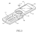
- FIG. 3 is a perspective view illustrating the second housing 102 of the portable terminal 100 shown in FIG. 1, after it is rotated 180°.
- the portable terminal 100 having the swing hinge device 200 according to an embodiment of the present invention comprises first and second housings 101 and 102, which are coupled to each other by the swing hinge device 200 in such a manner that they can be rotated while facing each other.
- the swing hinge device 200 is housed in a hinge unit 103, which is positioned on an end of the terminal 100.
- the hinge unit 103 may be provided with a keypad 131, which comprises predetermined function keys, on its upper surface.
- the first housing 101 is provided with a keypad 111 on its surface, which comprises a number of key arrays and a transmitter unit 113 which houses a microphone therein.
- the second housing 102 is coupled to the first housing 101 while facing it and is adapted to be rotated about a hinge axis A, which extends perpendicularly to a surface of the first housing 101, to open and close the keypad 111 and the transmitter unit 113 of the first housing 101.
- the second housing 102 is provided with, on its surface, a display device 121 and a receiver unit 123 which houses a speaker phone therein.
- the terminal 100 is provided with a cylindrical hinge unit 103 on its end, a portion of which protrudes from the end.
- the hinge unit 103 houses the swing hinge device 200 therein, which provides the hinge axis A extending perpendicularly to a surface of the first housing 101. Accordingly, the second housing 102 can be rotated while facing the first housing 101.
- the second housing 102 can be rotated 180° both clockwise and counterclockwise R from a position where it is folded on the first housing 101 while facing it.
- the second housing 102 is adapted to be rotated within a range of 360° or less on the first housing 101.
- the range of rotation is preferably limited in such a manner that the second housing 102 cannot be rotated more than 360° in any direction, that is, clockwise or counterclockwise. This is for the purpose of avoiding any damage to a flexible printed circuit board and the like, which extend through the swing hinge device 200 and electrically connect circuit devices (not shown), which are contained in the first and second housings 101 and 102.
- the swing hinge device 200 according to an embodiment of the present invention will now be described in detail with reference to FIGs. 4 to 7.
- the swing hinge device 200 comprises a hinge housing 201, a hinge shaft 204, first and second hinge cams 202 and 203, a resilient means 253, and a hinge stopper 267.
- the hinge housing 201 has a containing space 211 extending along its longitudinal direction. One end of the containing space 211 is an open end and the other end thereof is a closed end. At least one sliding groove 213 extends along the longitudinal direction on the inner wall of the containing space 211.
- a stopper plate 215 extends from the outer peripheral surface of the other end of the hinge housing 201 along its radial direction.
- the stopper plate 215 has a guide groove 217 formed on its surface along the circumferential direction of the hinge housing 201.
- the guide groove 217 has an avoidance groove 218 formed in a predetermined angle on its inner wall along the circumferential direction.
- the hinge housing 201 is fixedly coupled on the first housing 101 of the terminal 100. For this coupling, the stopper plate 215 may be provided with at least one fastening piece 219.
- a stopper washer 205 is coupled on the outer peripheral surface of the hinge housing 201.
- the stopper washer 205 is adapted to be rotated in the guide groove 217 and has a guide rib 251 extending in a predetermined angle from its outer peripheral surface.
- the guide rib 251 is adapted to be rotated in the avoidance groove 218 and thus the range of rotation of the guide rib 251, and therefore that of the stopper washer 205, are limited accordingly.
- One end 243 of the hinge shaft 204 protrudes from the open end of the hinge housing 201 and is fastened on the second housing 102, while the other end of the hinge shaft 204 extends along the longitudinal direction thereof and is rotatably coupled to the closed end of the hinge housing 201. Therefore, the hinge shaft 204 can be rotated in the hinge housing 201.
- the other end of the hinge shaft 204 protrudes from the closed end of the hinge housing 201 and has a fastening groove 241, which is formed on its outer surface and on which an E-ring 291 is fastened.
- a washer 293 may be interposed between the E-ring 291 and the hinge housing 201.
- the hinge shaft 204 is coupled with the first and second hinge cams 202 and 203, as well as the resilient means 253.
- the first hinge cam 202 is adapted to move linearly in the hinge housing 201.
- the first hinge cam 202 has a sliding protrusion 227 formed on its outer peripheral surface, which corresponds to the sliding groove 213 of the hinge housing 201, to guide the linear movement of the first hinge cam 202.
- the first hinge cam 202 has a slant surface 221 on its end and a hole 223, which extends through it along its longitudinal direction and through which the hinge shaft 204 pass.
- the slant surface 221 has cam stopper grooves 225 formed on the highest and lowest points thereof, respectively.
- the first hinge cam 202 is provided with a resilient force from the resilient means 253, such as a coil spring, which is supported on the closed end of the hinge housing 201.
- the second hinge cam 203 is fixedly coupled to the hinge shaft 204 and thus is rotated together with it.
- the hinge shaft 204 is provided with an angled fixation protrusion 245 on it end and the second hinge cam 203 is provided with a fixation groove 237 on its end, which corresponds to the fixation protrusion 245, as well as a hole 233, which extends through it along its longitudinal direction and is coupled with the hinge shaft 204.
- the second hinge cam 203 is fixedly coupled to the hinge shaft 204 by means of the fixation protrusion 245 and the fixation groove 237.
- the second hinge cam 203 has a slant surface 231 on the other end, which faces the corresponding slant surface of the first hinge cam 202.
- the slant surface 231 of the second hinge cam 203 has a cam stopper protrusion 235 protruding from its highest point, which corresponds to the cam stopper groove 225.
- the first and second hinge cams 202 and 203 are provided with a resilient force from the resilient means 253 and generate a rotational force.
- the resilient means 253 provides a resilient force in a direction such that the first hinge cam 202 is forced against the second hinge cam 203.
- the resilient force moves and forces the first hinge cam 202 against the second hinge cam 203.
- the second hinge cam 203 is then rotated in a direction such that the slant surfaces 221 and 231 of the first and second hinge cams 202 and 203 are forced against each other.
- the rotation of the second hinge cam 203 is accompanied by the rotation of the hinge shaft 204, and consequently that of the second housing 102.
- the slant surfaces 221 and 231 of the first and second hinge cam 202 and 203 have the cam stopper groove 225 and the cam stopper protrusion 235 positioned on their highest points, respectively. If the cam stopper groove 225 and the cam stopper protrusion 235 are engaged with each other, no rotational force is generated. If the cam stopper protrusion 235 is disengaged from the cam stopper groove 225 by an external force, the first hinge cam 202 is moved toward the second hinge cam 203 and the second hinge cam 203 is rotated in a direction such that the slant surfaces 221 and 231 are forced against each other. The second hinge cam 203 stops rotating if the cam stopper protrusion 235 is rotated 180° and reaches the lowest point of the slant surface 221 of the first hinge cam 202.
- the portable terminal 100 having the swing hinge device 200 is configured in such a manner that, due to the operation of the first and second hinge cams 202 and 203, the cam stopper groove 225 and the cam stopper protrusion 235 are engaged with each other if the first housing 201 is folded on the second housing 102 while facing it. Accordingly, if a user slightly rotates the second housing 102 and the cam stopper protrusion 235 is disengaged from the cam stopper groove 225, the second hinge cam 203 is rotated and thus the second housing 102 is rotated 180° relative to the first housing 101.
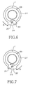
- the hinge stopper 267 is positioned on a side of the hinge shaft 204 and is rotated about it and together with it. Therefore, the hinge stopper 267 is moved in the guide groove 217 of the stopper plate 215 along the circumferential direction. The range of movement of the hinge stopper 267 is limited by the guide rib 251 of the stopper washer 205.
- the hinge stopper 267 if the hinge stopper 267 is rotated counterclockwise 1 ⁇ , it is moved and rotated 180° from its initial position I until stopped by the guide rib 251. On the other hand, if the hinge stopper 267 is rotated clockwise 2 ⁇ , it is rotated 180° from its initial position I until stopped by the guide rib 251. As such, the hinge stopper 267 can be rotated 180° both clockwise 2 ⁇ and counterclockwise 1 ⁇ from its initial position I, since it is rotated in a space provided by the avoidance groove 218. As a result, the hinge stopper 267 can be rotated in a range of 360°. However, the hinge stopper 267 is not allowed to be rotated more than 360° either clockwise 2 ⁇ or counterclockwise 1 ⁇ .
- the swing hinge device 200 has a hinge cap 206, which is coupled to an end of the hinge shaft 204, so that the hinge stopper 267 is rotated together with the hinge shaft 204 and, at the same time, the hinge shaft 204 is coupled with the second housing 102.
- the hinge cap 206 is fixed on an end of the hinge shaft 204 to close the open end of the hinge housing 201 and extends along the longitudinal direction to be coupled with the hinge housing 201 while surrounding it.
- the hinge cap 206 and the hinge shaft 204 are provided with respective fastening holes 261 and 247 on their ends, so that the hinge cap 206 can be fixed on the hinge shaft 204 by a screw 297.
- the hinge cap 206 has at least one fastening piece 265 extending from its outer peripheral surface along its diametric direction, which acts as a means for coupling it with the second housing 102.
- the hinge stopper 267 extends a predetermined distance from an end of the hinge cap 206 and is positioned in the guide groove 217 of the stopper plate 215.
- the swing hinge device 200 may be provided with a friction means for preventing the second housing 102 from being rotated abruptly.
- a friction means for preventing the second housing 102 from being rotated abruptly.
- a containing hole 263 is formed on the outer peripheral surface of the hinge cap 206 and extends along its longitudinal direction.
- a friction protrusion 207 is contained in the containing hole 263 and has an end, which is adapted contact the stopper plate 215 in a frictional relationship.
- a coil spring 271 is also contained in the containing hole 263 to provide the friction protrusion 207 with a resilient force.
- a screw 273 supports an end of the coil spring 271 and closes the containing hole 263.
- the swing hinge device 200 configured as above, is operated as follows: if the hinge stopper 267 is in its initial position I, as shown in FIGs. 6 and 7, the first housing 101 is folded on the second housing 102 while facing it and, at the same time, the highest points of the respective slant surfaces 221 and 231 of the first and second hinge cams 202 and 203 face each other. In particular, the cam stopper protrusion 235 and the cam stopper groove 225 of the respective first and second hinge cams 202 and 203 are engaged with each other.
- the cam stopper protrusion 235 is disengaged from the cam stopper groove 225 and the swing hinge device 200 rotates the second housing 102 up to 180° clockwise or counterclockwise. If the second housing 102 is rotated 180°, the rotation of the hinge stopper 267 is stopped by the guide rib 251. As such, the hinge stopper 267 prevents the second housing 102 from being rotated more that 180° from a position where it is folded on the first housing 101.
- the swing hinge device of a portable terminal has a pair of housings, which are coupled to each other in such a manner that they can be rotated, while facing each other, in a direction such that one of the housings is twisted relative to the other.
- the device also has a resilient means and a pair of cams to provide a rotational force, so that one of the housings can be opened semi-automatically to a position for enabling speech.
- the device is convenient to use.
- the device has a hinge stopper, stopper washer, and the like so that one of the housings is not allowed to be rotated more than 360° in a direction, relative to the other. This avoids any damage to a flexible printed circuit board and the like, which are positioned between the pair of housings.
Applications Claiming Priority (2)
| Application Number | Priority Date | Filing Date | Title |
|---|---|---|---|
| KR2003076886 | 2003-10-31 | ||
| KR1020030076886A KR100651412B1 (ko) | 2003-10-31 | 2003-10-31 | 휴대용 단말기의 스윙 힌지 장치 |
Publications (2)
| Publication Number | Publication Date |
|---|---|
| EP1528757A1 true EP1528757A1 (de) | 2005-05-04 |
| EP1528757B1 EP1528757B1 (de) | 2009-06-17 |
Family
ID=34420693
Family Applications (1)
| Application Number | Title | Priority Date | Filing Date |
|---|---|---|---|
| EP04025770A Expired - Fee Related EP1528757B1 (de) | 2003-10-31 | 2004-10-29 | Scharniergelenk für ein tragbares Endgerät |
Country Status (5)
| Country | Link |
|---|---|
| US (1) | US7036186B2 (de) |
| EP (1) | EP1528757B1 (de) |
| KR (1) | KR100651412B1 (de) |
| CN (1) | CN1324934C (de) |
| DE (1) | DE602004021545D1 (de) |
Cited By (4)
| Publication number | Priority date | Publication date | Assignee | Title |
|---|---|---|---|---|
| EP1777924A1 (de) * | 2005-10-18 | 2007-04-25 | Nokia Corporation | Drehbares tragbares elektronisches Gerät mit Vorspannmechanismus |
| EP1840697A1 (de) * | 2006-03-31 | 2007-10-03 | Casio Hitachi Mobile Communications Co., Ltd. | Gelenkvorrichtung mit Dichtungsring und tragbares elektronisches Gerät |
| WO2012136884A1 (en) * | 2011-04-04 | 2012-10-11 | Nokia Corporation | Rotating and moving mechanism |
| FR3063561A1 (fr) * | 2017-03-02 | 2018-09-07 | Ingenico Group | Dispositif de support pour terminal de paiement |
Families Citing this family (20)
| Publication number | Priority date | Publication date | Assignee | Title |
|---|---|---|---|---|
| KR100946645B1 (ko) * | 2002-03-19 | 2010-03-09 | 파나소닉 주식회사 | 힌지 및 이를 구비한 개폐식 휴대단말장치 |
| CN101834922A (zh) * | 2003-03-03 | 2010-09-15 | 莱尔德科技Map有限公司 | 铰链组件 |
| KR100566276B1 (ko) * | 2003-10-17 | 2006-03-30 | 삼성전자주식회사 | 휴대용 단말기 및 그의 스윙 힌지 모듈 |
| KR100630075B1 (ko) * | 2004-03-12 | 2006-09-27 | 삼성전자주식회사 | 휴대 단말기의 스윙 힌지 장치 |
| JP4325540B2 (ja) * | 2004-11-12 | 2009-09-02 | パナソニック株式会社 | 開閉装置 |
| JP2006258116A (ja) * | 2005-03-15 | 2006-09-28 | Matsushita Electric Ind Co Ltd | 開閉装置 |
| US7400908B2 (en) * | 2005-04-07 | 2008-07-15 | Nokia Corporation | Mobile communication terminal |
| KR20060122241A (ko) * | 2005-05-26 | 2006-11-30 | 삼성전자주식회사 | 힌지 모듈을 구비하는 휴대용 단말기 |
| WO2007069834A1 (en) * | 2005-12-13 | 2007-06-21 | Laird Technologies Map Co., Ltd | A swing mechanism for display part of cellular phone |
| US7866000B2 (en) * | 2006-07-24 | 2011-01-11 | Samsung Electronics Co., Ltd | Swing hinge apparatus of portable terminal |
| US7665186B2 (en) * | 2006-10-30 | 2010-02-23 | Sony Ericsson Mobile Communications Ab | Hinge with anti-skew features |
| US7631397B2 (en) * | 2007-09-06 | 2009-12-15 | Cheng Uei Precision Industry Co., Ltd. | Hinge |
| US7743468B2 (en) * | 2007-11-13 | 2010-06-29 | Shin Zu Shing Co., Ltd. | Hinge assembly |
| US7836550B2 (en) * | 2007-12-27 | 2010-11-23 | Cheng Uei Precision Industry Co., Ltd. | Damping hinge device |
| CN101729615B (zh) * | 2008-10-24 | 2014-11-12 | 比亚迪股份有限公司 | 一种便携式终端 |
| CN101861062A (zh) * | 2009-04-13 | 2010-10-13 | 深圳富泰宏精密工业有限公司 | 便携式电子装置 |
| KR101594179B1 (ko) * | 2009-07-30 | 2016-02-16 | 삼성전자주식회사 | 힌지 장치를 구비하는 휴대용 단말기 |
| US10434625B2 (en) * | 2016-09-04 | 2019-10-08 | Marjan Majcen | Latching mechanism using deployable arms |
| TWM549296U (zh) * | 2017-07-13 | 2017-09-21 | 信錦企業股份有限公司 | 支撐架 |
| CN108972516A (zh) * | 2018-09-19 | 2018-12-11 | 天津大衍天成科技有限公司 | 一种纯人力外骨骼躯干系统 |
Citations (4)
| Publication number | Priority date | Publication date | Assignee | Title |
|---|---|---|---|---|
| JP2002344592A (ja) * | 2001-05-16 | 2002-11-29 | Kyocera Corp | 携帯端末装置 |
| WO2003047218A1 (en) * | 2001-11-27 | 2003-06-05 | Sony Ericsson Mobile Communications Japan, Inc. | Portable terminal |
| GB2387063A (en) * | 2002-03-29 | 2003-10-01 | Nec Corp | Foldable information apparatus with rotatable display and camera |
| EP1353488A2 (de) | 2002-04-10 | 2003-10-15 | Nec Corporation | Tragbares und klappbares Mobilkommunikationsendgerät |
Family Cites Families (18)
| Publication number | Priority date | Publication date | Assignee | Title |
|---|---|---|---|---|
| JP2534114Y2 (ja) * | 1991-09-30 | 1997-04-30 | 日本電気株式会社 | 折畳型電子機器の構造 |
| JP3732619B2 (ja) * | 1997-06-16 | 2006-01-05 | 加藤電機株式会社 | ヒンジ装置 |
| TW411069U (en) * | 1997-10-08 | 2000-11-01 | Kato Electric & Machinary Co | Hinge device |
| SE511799C2 (sv) * | 1998-03-24 | 1999-11-29 | Ericsson Telefon Ab L M | Gångledsanordning vid en mobiltelefonapparat med lucka |
| JP4498516B2 (ja) | 1999-04-01 | 2010-07-07 | Sumco Techxiv株式会社 | 単結晶インゴット製造装置及び方法 |
| TW448989U (en) * | 2001-01-16 | 2001-08-01 | Lumens Technology Inc | Hinge structure for retractable arm |
| US6785936B2 (en) * | 2001-02-26 | 2004-09-07 | Sugatsune Kogyo Co., Ltd. | Hinge device |
| KR200241123Y1 (ko) * | 2001-04-25 | 2001-10-12 | 원종림 | 이동통신단말기의 커버 개폐장치 |
| KR100665709B1 (ko) * | 2001-04-26 | 2007-01-10 | 피닉스코리아 주식회사 | 힌지장치 |
| AUPR480701A0 (en) * | 2001-05-04 | 2001-05-31 | Centor Products Pty Ltd | A lockable carrier hinge assembly |
| US7006853B2 (en) * | 2001-08-24 | 2006-02-28 | Samsung Electronics Co., Ltd. | Rotary type hinge module for portable wireless terminal |
| JP2003120653A (ja) * | 2001-10-17 | 2003-04-23 | Ohashi Technica Inc | ヒンジ装置及びそれを用いた携帯電話機 |
| JP3906702B2 (ja) * | 2002-02-12 | 2007-04-18 | 松下電器産業株式会社 | 開閉装置及びこれを用いた電子機器 |
| JP4025118B2 (ja) * | 2002-05-21 | 2007-12-19 | ソニー・エリクソン・モバイルコミュニケーションズ株式会社 | ヒンジ装置並びにヒンジ装置を用いた電子機器 |
| TW584233U (en) * | 2003-01-16 | 2004-04-11 | Quanta Comp Inc | A swivel hinge with angular fix structure |
| FI118668B (fi) * | 2003-04-01 | 2008-01-31 | Samsung Electro Mech | Matkapuhelin ja sen automaattinen pyöritysmenetelmä |
| US6845546B1 (en) * | 2003-06-20 | 2005-01-25 | Shin Zu Shing Co., Ltd. | Hinge assembly with a rotation seat available to rotate in both latitudinal and longitudinal directions with respect to a fixing seat |
| KR100557078B1 (ko) * | 2003-11-06 | 2006-03-03 | 삼성전자주식회사 | 디스플레이 회전형 휴대 단말기의 힌지 장치 |
-
2003
- 2003-10-31 KR KR1020030076886A patent/KR100651412B1/ko not_active IP Right Cessation
-
2004
- 2004-09-16 US US10/942,131 patent/US7036186B2/en not_active Expired - Fee Related
- 2004-10-29 EP EP04025770A patent/EP1528757B1/de not_active Expired - Fee Related
- 2004-10-29 CN CNB2004100901451A patent/CN1324934C/zh not_active Expired - Fee Related
- 2004-10-29 DE DE602004021545T patent/DE602004021545D1/de active Active
Patent Citations (4)
| Publication number | Priority date | Publication date | Assignee | Title |
|---|---|---|---|---|
| JP2002344592A (ja) * | 2001-05-16 | 2002-11-29 | Kyocera Corp | 携帯端末装置 |
| WO2003047218A1 (en) * | 2001-11-27 | 2003-06-05 | Sony Ericsson Mobile Communications Japan, Inc. | Portable terminal |
| GB2387063A (en) * | 2002-03-29 | 2003-10-01 | Nec Corp | Foldable information apparatus with rotatable display and camera |
| EP1353488A2 (de) | 2002-04-10 | 2003-10-15 | Nec Corporation | Tragbares und klappbares Mobilkommunikationsendgerät |
Non-Patent Citations (1)
| Title |
|---|
| PATENT ABSTRACTS OF JAPAN vol. 2003, no. 03 5 May 2003 (2003-05-05) * |
Cited By (6)
| Publication number | Priority date | Publication date | Assignee | Title |
|---|---|---|---|---|
| EP1777924A1 (de) * | 2005-10-18 | 2007-04-25 | Nokia Corporation | Drehbares tragbares elektronisches Gerät mit Vorspannmechanismus |
| EP1840697A1 (de) * | 2006-03-31 | 2007-10-03 | Casio Hitachi Mobile Communications Co., Ltd. | Gelenkvorrichtung mit Dichtungsring und tragbares elektronisches Gerät |
| US7792555B2 (en) | 2006-03-31 | 2010-09-07 | Casio Hitachi Mobile Communications Co., Ltd. | Hinge device and portable electronic apparatus |
| WO2012136884A1 (en) * | 2011-04-04 | 2012-10-11 | Nokia Corporation | Rotating and moving mechanism |
| US8687376B2 (en) | 2011-04-04 | 2014-04-01 | Nokia Corporation | Rotating and moving mechanism |
| FR3063561A1 (fr) * | 2017-03-02 | 2018-09-07 | Ingenico Group | Dispositif de support pour terminal de paiement |
Also Published As
| Publication number | Publication date |
|---|---|
| KR20050041646A (ko) | 2005-05-04 |
| EP1528757B1 (de) | 2009-06-17 |
| US20050091795A1 (en) | 2005-05-05 |
| CN1324934C (zh) | 2007-07-04 |
| CN1625325A (zh) | 2005-06-08 |
| KR100651412B1 (ko) | 2006-11-28 |
| US7036186B2 (en) | 2006-05-02 |
| DE602004021545D1 (de) | 2009-07-30 |
Similar Documents
| Publication | Publication Date | Title |
|---|---|---|
| US7036186B2 (en) | Swing hinge device for a portable terminal | |
| US7522946B2 (en) | Hinge apparatus for mobile communication terminals | |
| KR100630139B1 (ko) | 이축 힌지 장치를 구비하는 휴대용 단말기 | |
| US7844050B2 (en) | Biaxial hinge device for mobile terminal and mounting mechanism thereof | |
| KR100490356B1 (ko) | 휴대용 무선 단말기의 로터리형 힌지 장치 | |
| EP1559859B1 (de) | Rotierendes Scharniermodul für ein tragbares Endgerät | |
| KR960000155B1 (ko) | 힌지 장치 | |
| US7266864B2 (en) | Rotary type hinge device for portable wireless terminal | |
| US7146200B2 (en) | Camera lens mounting device of folder type telephone | |
| US8554285B2 (en) | Swing-type portable terminal | |
| US7184805B2 (en) | Hinge device of swing-type portable terminal | |
| US7287302B2 (en) | Swing hinge device of portable terminal | |
| US20040203517A1 (en) | Mobile terminal and hinge device thereof | |
| US20060112518A1 (en) | Cover restricting mechanism | |
| US7334294B2 (en) | Hinge and foldable electronic device using the hinge | |
| US20050138772A1 (en) | Hinge device and portable terminal having the same | |
| US8082632B2 (en) | Hinge device for portable terminal having sub-housing stopper | |
| US20050020327A1 (en) | Speaker-up type portable terminal | |
| US7657027B2 (en) | Portable terminal with hinge apparatus | |
| KR101126428B1 (ko) | 휴대용 단말기의 2 축 힌지 장치 | |
| KR100724873B1 (ko) | 힌지 장치를 구비하는 휴대용 단말기 | |
| KR101138539B1 (ko) | 휴대 단말기의 힌지 장치 | |
| KR100238522B1 (ko) | 플립형 휴대용 단말기의 플립커버 개폐장치 | |
| KR20050035032A (ko) | 휴대용 단말기의 힌지장치 | |
| KR20060055168A (ko) | 회전성 힌지 더미를 구비하는 휴대용 단말기 |
Legal Events
| Date | Code | Title | Description |
|---|---|---|---|
| PUAI | Public reference made under article 153(3) epc to a published international application that has entered the european phase |
Free format text: ORIGINAL CODE: 0009012 |
|
| 17P | Request for examination filed |
Effective date: 20041029 |
|
| AK | Designated contracting states |
Kind code of ref document: A1 Designated state(s): AT BE BG CH CY CZ DE DK EE ES FI FR GB GR HU IE IT LI LU MC NL PL PT RO SE SI SK TR |
|
| AX | Request for extension of the european patent |
Extension state: AL HR LT LV MK |
|
| AKX | Designation fees paid |
Designated state(s): DE FR GB |
|
| GRAP | Despatch of communication of intention to grant a patent |
Free format text: ORIGINAL CODE: EPIDOSNIGR1 |
|
| GRAS | Grant fee paid |
Free format text: ORIGINAL CODE: EPIDOSNIGR3 |
|
| GRAA | (expected) grant |
Free format text: ORIGINAL CODE: 0009210 |
|
| AK | Designated contracting states |
Kind code of ref document: B1 Designated state(s): DE FR GB |
|
| REG | Reference to a national code |
Ref country code: GB Ref legal event code: FG4D |
|
| REF | Corresponds to: |
Ref document number: 602004021545 Country of ref document: DE Date of ref document: 20090730 Kind code of ref document: P |
|
| PLBE | No opposition filed within time limit |
Free format text: ORIGINAL CODE: 0009261 |
|
| STAA | Information on the status of an ep patent application or granted ep patent |
Free format text: STATUS: NO OPPOSITION FILED WITHIN TIME LIMIT |
|
| 26N | No opposition filed |
Effective date: 20100318 |
|
| REG | Reference to a national code |
Ref country code: DE Ref legal event code: R082 Ref document number: 602004021545 Country of ref document: DE Representative=s name: GRUENECKER PATENT- UND RECHTSANWAELTE PARTG MB, DE Ref country code: DE Ref legal event code: R082 Ref document number: 602004021545 Country of ref document: DE Representative=s name: GRUENECKER, KINKELDEY, STOCKMAIR & SCHWANHAEUS, DE |
|
| PGFP | Annual fee paid to national office [announced via postgrant information from national office to epo] |
Ref country code: GB Payment date: 20140924 Year of fee payment: 11 |
|
| PGFP | Annual fee paid to national office [announced via postgrant information from national office to epo] |
Ref country code: FR Payment date: 20140925 Year of fee payment: 11 Ref country code: DE Payment date: 20140924 Year of fee payment: 11 |
|
| REG | Reference to a national code |
Ref country code: DE Ref legal event code: R119 Ref document number: 602004021545 Country of ref document: DE |
|
| GBPC | Gb: european patent ceased through non-payment of renewal fee |
Effective date: 20151029 |
|
| PG25 | Lapsed in a contracting state [announced via postgrant information from national office to epo] |
Ref country code: GB Free format text: LAPSE BECAUSE OF NON-PAYMENT OF DUE FEES Effective date: 20151029 Ref country code: DE Free format text: LAPSE BECAUSE OF NON-PAYMENT OF DUE FEES Effective date: 20160503 |
|
| REG | Reference to a national code |
Ref country code: FR Ref legal event code: ST Effective date: 20160630 |
|
| PG25 | Lapsed in a contracting state [announced via postgrant information from national office to epo] |
Ref country code: FR Free format text: LAPSE BECAUSE OF NON-PAYMENT OF DUE FEES Effective date: 20151102 |