EP1559859B1 - Rotierendes Scharniermodul für ein tragbares Endgerät - Google Patents
Rotierendes Scharniermodul für ein tragbares Endgerät Download PDFInfo
- Publication number
- EP1559859B1 EP1559859B1 EP05001603A EP05001603A EP1559859B1 EP 1559859 B1 EP1559859 B1 EP 1559859B1 EP 05001603 A EP05001603 A EP 05001603A EP 05001603 A EP05001603 A EP 05001603A EP 1559859 B1 EP1559859 B1 EP 1559859B1
- Authority
- EP
- European Patent Office
- Prior art keywords
- hinge
- rotary
- folder
- portable terminal
- housing
- Prior art date
- Legal status (The legal status is an assumption and is not a legal conclusion. Google has not performed a legal analysis and makes no representation as to the accuracy of the status listed.)
- Expired - Lifetime
Links
Images


Classifications
-
- H—ELECTRICITY
- H04—ELECTRIC COMMUNICATION TECHNIQUE
- H04B—TRANSMISSION
- H04B1/00—Details of transmission systems, not covered by a single one of groups H04B3/00 - H04B13/00; Details of transmission systems not characterised by the medium used for transmission
- H04B1/38—Transceivers, i.e. devices in which transmitter and receiver form a structural unit and in which at least one part is used for functions of transmitting and receiving
-
- H—ELECTRICITY
- H04—ELECTRIC COMMUNICATION TECHNIQUE
- H04M—TELEPHONIC COMMUNICATION
- H04M1/00—Substation equipment, e.g. for use by subscribers
- H04M1/02—Constructional features of telephone sets
- H04M1/0202—Portable telephone sets, e.g. cordless phones, mobile phones or bar type handsets
- H04M1/0206—Portable telephones comprising a plurality of mechanically joined movable body parts, e.g. hinged housings
- H04M1/0208—Portable telephones comprising a plurality of mechanically joined movable body parts, e.g. hinged housings characterized by the relative motions of the body parts
- H04M1/021—Portable telephones comprising a plurality of mechanically joined movable body parts, e.g. hinged housings characterized by the relative motions of the body parts using combined folding and rotation motions
- H04M1/0212—Portable telephones comprising a plurality of mechanically joined movable body parts, e.g. hinged housings characterized by the relative motions of the body parts using combined folding and rotation motions with a two degrees of freedom mechanism, i.e. folding around a first axis and rotating around a second axis perpendicular to the first
-
- E—FIXED CONSTRUCTIONS
- E05—LOCKS; KEYS; WINDOW OR DOOR FITTINGS; SAFES
- E05D—HINGES OR SUSPENSION DEVICES FOR DOORS, WINDOWS OR WINGS
- E05D11/00—Additional features or accessories of hinges
- E05D11/10—Devices for preventing movement between relatively-movable hinge parts
- E05D11/1028—Devices for preventing movement between relatively-movable hinge parts for maintaining the hinge in two or more positions, e.g. intermediate or fully open
- E05D11/1078—Devices for preventing movement between relatively-movable hinge parts for maintaining the hinge in two or more positions, e.g. intermediate or fully open the maintaining means acting parallel to the pivot
-
- E—FIXED CONSTRUCTIONS
- E05—LOCKS; KEYS; WINDOW OR DOOR FITTINGS; SAFES
- E05D—HINGES OR SUSPENSION DEVICES FOR DOORS, WINDOWS OR WINGS
- E05D3/00—Hinges with pins
- E05D3/06—Hinges with pins with two or more pins
- E05D3/10—Hinges with pins with two or more pins with non-parallel pins
-
- E—FIXED CONSTRUCTIONS
- E05—LOCKS; KEYS; WINDOW OR DOOR FITTINGS; SAFES
- E05Y—INDEXING SCHEME ASSOCIATED WITH SUBCLASSES E05D AND E05F, RELATING TO CONSTRUCTION ELEMENTS, ELECTRIC CONTROL, POWER SUPPLY, POWER SIGNAL OR TRANSMISSION, USER INTERFACES, MOUNTING OR COUPLING, DETAILS, ACCESSORIES, AUXILIARY OPERATIONS NOT OTHERWISE PROVIDED FOR, APPLICATION THEREOF
- E05Y2999/00—Subject-matter not otherwise provided for in this subclass
Definitions
- the present invention relates to a hinge device for a portable terminal. More particularly, the present invention relates to a rotary-type hinge device adapted to open/close a flip or a folder of a portable terminal from/on the body of the terminal and to rotate the flip or folder, while it is opened, in such a manner that the front and rear surfaces thereof can be reversed.
- portable terminals are classified as bar-type terminals, flip-type terminals, or folder-type terminals according to their appearance.
- Bar-type terminals have a single body housing, on which data input/output means and transmitter/receiver modules are positioned.
- Flip-type portable terminals have a body, a flip, and a hinge device for connecting the body to the flip.
- Folder-type terminal have a body, a folder, and a hinge device for rotatably connecting the body to the folder.
- the folder-type terminal is opened/closed as the folder is rotated and has the advantage of having a compact size. For this reason, folder-type terminals have been increasing in popularity.
- a terminal has been manufactured which has a pair of housings adapted to be opened/closed through a sliding or swing motion while the housings are facing each other.
- a complex-type terminal also has been manufactured, which is configured as a folder-type terminal and can perform a swing motion.
- a hinge device for realizing the opening/closing motion of the complex-type terminal is disclosed in Korean Laid-Open Patent Publication No. 2003-17321 (March 3, 2003 ) filed by the present applicant, which corresponds to U.S. Patent Application No. 226,712 (August 23, 2002 ).
- the hinge device is a rotary type and has a folder which can be rotated, while it is opened, in such a manner that the front and rear surfaces thereof can be reversed.
- Another example of a hinge device is disclosed in Document JP 11182528A .
- Portable terminals are undergoing rapid improvements not only in their appearance, but also in their function.
- portable terminals equipped with camera lens assemblies already occupy a significant market share in the portable terminal market and the quality of the images produced are comparable to that of digital cameras.
- portable terminals as a photography device may be alleviated by the complex opening/closing motion
- portable terminals still have a problem in that the motion cannot be performed in a stable manner.
- the folder cannot be maintained in a stable state when it is opened. This makes it difficult to take pictures using the terminals.
- an object of the present invention is to provide a rotary-type hinge device capable of providing a stable opening/closing motion of a portable terminal having a folder adapted to be opened/closed through a complex motion.
- Another object of the present invention is to provide a rotary-type hinge device of a portable terminal capable of continuously maintaining the folder of the terminal, when it is opened, in a stable state.
- FIG. 1 is an exploded perspective view illustrating a rotary-type hinge device 100 of a portable terminal according to a preferred embodiment of the present invention
- FIG. 2 is a perspective view showing the internal structure of the rotary-type hinge device 100 of FIG. 1 .
- the rotary-type hinge device 100 of a portable terminal according to an embodiment of the present invention comprises a first hinge housing 101, a first hinge module 200, and a second hinge module 300.
- the first hinge housing 101 has a center hinge arm 111 extending along a first hinge axis A1, as well as a folder base 117 formed on the center hinge arm 111 and extending along the first hinge axis A1.
- the center hinge arm 111 has a containing hole 113 formed on its end to contain the first hinge module 200 therein.
- the containing hole 113 has a guide groove 115 formed on its inner wall along its longitudinal direction.
- the second hinge module 300 is coupled to the inner wall of the first hinge housing 101 in a predetermined location.
- the second hinge module 300 has a rotary shaft 301 adapted to be rotated about a second hinge axis A2, which is perpendicular to the first hinge axis A1.
- the first hinge module 200 comprises a second hinge housing 201, a hinge cam 203, a hinge shaft 204, a support shaft 205, and a coil spring 206.
- the support shaft 205 is provided with a guide plate 253 on its end.
- the second housing 201 has the shape of a cylinder extending along the first hinge axis A1. An end of the second housing 201 is closed by the hinge shaft 204.
- the second housing 201 contains the hinge cam 203 and the coil spring 206 in its interior 211 and has a guide groove 213 formed on its inner wall along its longitudinal direction.
- the hinge cam 203 has a through-hole 235 extending along the first hinge axis A1, as well as crests 233 and troughs 231 alternating along its circumferential direction.
- a guide protrusion 237 is formed on the outer peripheral surface of the hinge cam 203 and is adapted to move linearly in the guide groove 213 of the second hinge housing 201. Consequently, the hinge cam 203 can move linearly in the second hinge housing 201.
- the hinge shaft 204 is assembled in such a manner that it protrudes out of an end of the second hinge housing 201 and has a through-hole 245 extending along the first hinge axis A1.
- the hinge shaft 204 has crests 243 and troughs 241 formed on its surface, which face the crests 233 and troughs 231 of the hinge cam 203.
- the hinge shaft 204 protrudes out of an end of the center hinge arm 111.
- the coil spring 206 is supported on the inner wall of an end of the second hinge housing 201 and on the hinge cam 203 to provide a resilient force in such a direction that the hinge cam 203 is forced against the hinge shaft 204.
- a rotational force is generated and applied in such a direction that the respective crests and troughs are engaged with one another.
- the support shaft 205 penetrates the second hinge housing 201 along the first hinge axis A1 and an end thereof is fixed on the hinge shaft 204.
- the first hinge module 200 If the first hinge housing 201 is rotated about the first hinge axis A1, the first hinge module 200 generates a rotational force in the direction of rotation of the first housing 201 or in the opposite direction, depending on the angle of rotation.
- the second hinge module 300 comprises a rotary shaft 301, a rotary cam 303, a support shaft 304, and a coil spring 306.
- the rotary shaft 301 is adapted to be rotated about the second hinge axis A2.
- the rotary shaft 301 has the shape of a cylinder extending along the second hinge axis A2 and contains the rotary cam 303 and the coil spring 306 in its interior 311.
- the rotary shaft 301 has a guide groove 313 formed on its inner wall along its longitudinal direction and a stopper plate 317 extending from the outer peripheral surface of an end thereof along its radial direction.
- the rotary shaft 301 also has a pair of fastening arms 315 extending from the outer peripheral surface of the other end thereof in a direction away from each other.
- the rotary cam 303 has crests 333 and troughs 331 formed on its end while alternating along its circumferential direction.
- a guide protrusion 337 is formed on the outer peripheral surface of the rotary cam 303 and is adapted to move linearly in the guide groove 313 of the rotary shaft 301. Consequently, the rotary cam 303 can move linearly in the rotary shaft 301.
- the support shaft 304 closes an end of the rotary shaft 301, extends through it, and protrudes out of the other end thereof.
- the support shaft 304 has a fastening groove 343 formed on its end, to which O-rings or E-rings 351 and 353 are fastened, when it protrudes out of the other end of the rotary shaft 301. Consequently, the support shaft 304 is rotatably coupled to the rotary shaft 301.
- the support shaft 304 also has crests 345 formed on its outer peripheral surface 341 in predetermined locations, which are adapted to face the crests 333 or the troughs 331 of the rotary cam 303.
- the support shaft 304 which is rotatably coupled to the rotary shaft 301, passes through the folder base 117 and is fixed on the inner wall of the first hinge housing 101.
- the fastening arm 315 of the rotary shaft 301 protrudes out of an end of the folder base 117.
- the coil spring 306 is contained in the rotary shaft 301 and provides a resilient force in such a direction that the rotary cam 303 is forced against the crests 345 of the support shaft 304. As a result, the troughs 331 of the rotary cams 303 are engaged with the crests 345 of the support shaft 304. If the support shaft 304 is rotated relative to the rotary shaft 301, the resilient force from the coil spring 306 rotates the support shaft 304 in such a direction that the crests 345 are again engaged with the troughs 331 of the rotary cam 303.
- the troughs 331 of the rotary cam 303 are preferably formed with an equiangular interval along the circumferential direction of the rotary cam 303 and, for example, they are formed with an interval of 90° in an embodiment of the present invention.
- the support shaft 304 is then adapted to stop rotating with an interval of 90°.
- the stopper plate 317 interferes with the guide plate 253, depending on the angle of rotation of the first hinge housing 101 about the first hinge axis A1, and limits the rotation of the rotary shaft 301 about the second hinge axis A2.
- the stopper plate 317 limits the rotation of the first hinge housing 101 about the first hinge axis A1. If the first hinge housing 101 fails to be rotated a predetermined angle or more about the first hinge axis A1, the guide plate 253 limits the rotation of the rotary shaft 301. Accordingly, the rotary shaft 301 cannot be rotated until the first hinge housing 101 is rotated a predetermined angle or more.
- the stopper plate 317 is positioned on a surface of the guide plate 253. In this state, the first hinge housing 101 cannot be rotated in such a direction that it returns to the pre-rotation position. This will be described in more detail with reference to FIGs. 3 to 8 .
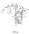
- a portable terminal 1 equipped with the rotary-type hinge device 100 has a body 10 and a folder 20, both of which are rotatably coupled to each other by the hinge device 100.
- the body 10 is provided with a keypad 111 and a microphone 13 on its front surface and an antenna device 19 on the upper end of its rear surface.
- the folder 20 is provided with a display device 21 on a surface which faces the body 10.
- the body 10 is provided with a pair of side hinge arms 15 on the upper end of its front surface to accommodate the hinge device 100.
- the center hinge arm 111 of the hinge device 100 is rotatably coupled between the pair of side hinge arms 15.
- the hinge shaft 204 which protrudes out of an end of the center hinge arm 111, is fixed on the internal surface of one of the side hinge arms 15.
- first hinge housing 101 If the first hinge housing 101 is rotated about the first hinge axis A1, the hinge cam 203 is rotated together. The crests and troughs of the hinge cam 203 and the hinge shaft 204 are then disengaged from one another and a rotational force is generated, which is applied in the direction of rotation or in the opposite direction, depending on the angle of rotation of the first hinge housing 101.
- the folder 20 is coupled on an end of the folder base 117 and then can be rotated about the second hinge axis A2.
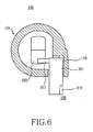
- the first and second hinge modules 200 and 300 of the hinge device 100 are positioned in such a manner as shown in FIGs. 2 and 6 .
- the stopper plate 317 interferes with the guide plate 253 and limits the rotation of the rotary shaft 301 about the second hinge axis A2.
- the folder 20 and the first hinge housing 101 When the folder 20 and the first hinge housing 101 are rotated 90° or more about the first hinge axis A1, the folder 20 can be rotated about the second hinge axis A2.
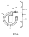
- the rotation of the folder 20 about the second hinge axis A2 and the motion of the hinge device 100 are shown in FIGs. 4 , 5 , and 8 .
- the present embodiment is configured in such a manner that, when the folder 20 and the first hinge housing 101 are rotated 90° or more from the body 10, the folder 20 can be rotated about the second hinge axis A2. If the folder 20 is rotated about the second hinge axis A2, the stopper plate 317 interferes with a lateral surface of the guide plate 235 and limits the rotation of the folder 20 about the first hinge axis A1 in a direction approaching the body 10.
- the stopper plate 317 interferes with the inner wall 119 of the first hinge housing 101 and limits further rotation of the folder 20 about the second hinge axis A2. If the troughs 331 of the rotary cam 303 are formed with an interval of 90°, the folder 20 is adapted to stop rotating with an interval of 90°. Accordingly, after being rotated 90° about the first hinge axis A1, as shown in FIG. 4 , the folder 20 can be rotated again about the second hinge axis A2 and then continuously maintained in a stable state.
- the body 10 of the terminal is equipped with a camera lens assembly on a surface, it can be conveniently used for the user to take pictures of their self or of a desired object, after the folder 20 is rotated 90° about the first and second hinge axes A1 and A2, respectively.
- the folder 20 is rotated 90° about the first and second hinge axes A1 and A2, respectively, the troughs 331 of the rotary cam 303 are engaged with the crests 345 of the support shaft 304 and, at the same time, the stopper plate 317 interferes with the inner wall 119 of the first hinge housing 101 and the lateral surface of the guide plate 253, so that the folder 20 is continuously maintained in a stable state.
- the guide plate 253 is positioned on a side of the stopper plate 317 and limits the rotation of the folder 20, which is adapted to be rotated about the first hinge axis A1, about the second hinge axis A2.
- the folder 20 can be rotated about the second hinge axis A2 in both clockwise and counterclockwise directions.
- guide plates may be positioned on both sides of the stopper plate 317 to limit the rotation of the folder 20 about the second hinge axis A2 in both clockwise and counterclockwise directions.
- the rotary-type hinge device of a portable terminal has a stopper plate and a guide plate, which are positioned perpendicularly to each other, so that the rotation and maintaining of the folder can be stabilized. Therefore, the device can be applied to a terminal which is equipped with a camera lens assembly and is conveniently used to take pictures.
Landscapes
- Engineering & Computer Science (AREA)
- Signal Processing (AREA)
- Computer Networks & Wireless Communication (AREA)
- Telephone Set Structure (AREA)
- Pivots And Pivotal Connections (AREA)
Claims (15)
- Drehscharniervorrichtung (100) eines Mobil-Endgerätes zum Drehen eines Klappteils (20) des Endgerätes von einem Korpus (10) des Mobil-Endgerätes um eine erste Scharnierachse (A1) und um eine zweite Scharnierachse (A2), die senkrecht zur ersten Scharnierachse verläuft, wobei die Vorrichtung Folgendes umfasst:ein erstes Scharniermodul (200), das mit dem Korpus gekoppelt ist und dafür ausgelegt ist, das Klappteil um die erste Scharnierachse (A1) zu drehen;ein zweites Scharniermodul (300), das mit dem Klappteil gekoppelt ist und dafür ausgelegt ist, das Klappteil um die zweite Scharnierachse (A2) zu drehen, wenn das Klappteil um einen, oder um mehr als einen, zuvor festgelegten Winkel um die erste Scharnierachse (A1) gedreht wird;ein erstes Scharniergehäuse (101), das an den Korpus (10) gekoppelt ist, wobei das erste Scharniergehäuse dafür ausgelegt ist, um die erste Scharnierachse (A1) gedreht zu werden, und das erste und das zweite Scharniermodul (200, 300) umfasst;eine Führung (253), die an dem ersten Scharniermodul (200) angeordnet und neben dem zweiten Scharniermodul (300) positioniert ist; undeinen Endanschlag (317), der an dem zweiten Scharniermodul (300) angeordnet und dafür ausgelegt ist, die Drehung des Klappteils um die zweite Scharnierachse (A2) zu begrenzen, wenn das Klappteil (20) innerhalb eines zuvor festgelegten Winkels um die erste Scharnierachse (A1) gedreht wird,wobei der Endanschlag eine Endanschlagplatte (317) ist, die an einem Ende des zweiten Scharniermoduls (300) angeordnet ist und die sich in einer Richtung senkrecht zur zweiten Scharnierachse (A2) erstreckt,wobei die Endanschlagplatte (317) dafür ausgelegt ist, als Anschlag für eine Innenwand (119) des ersten Scharniergehäuses (101) zu dienen und eine weitere Drehung des Klappteils zu begrenzen, wenn das Klappteil um 90° von dem Korpus gedreht wird, um geöffnet zu werden, und erneut um einen zuvor festgelegten Winkel um die zweite Scharnierachse (A2) gedreht wird.
- Drehscharniervorrichtung eines Mobil-Endgerätes nach Anspruch 1, wobei die Führung eine Führungsplatte (253) ist, die an einem Ende des ersten Scharniermoduls (200) angeordnet ist und die neben dem zweiten Scharniermodul (300) positioniert ist.
- Drehscharniervorrichtung eines Mobil-Endgerätes nach Anspruch 1, wobei die Führung eine Führungsplatte (253) ist, die an einem Ende des ersten Scharniermoduls (200) angeordnet ist und die neben dem zweiten Scharniermodul positioniert ist, und die Endanschlagplatte (317) dafür ausgelegt ist, als Anschlag für die Führungsplatte (253) zu dienen.
- Drehscharniervorrichtung eines Mobil-Endgerätes nach Anspruch 1, wobei die Führungsplatte (253) und die Endanschlagplatte (317) dafür ausgelegt sind, aneinander zu schlagen und die Drehung des Klappteils zu begrenzen, wenn das Klappteil (20) innerhalb von 90° aus einer Position, in der es an dem Korpus (10) ausgeklappt ist, gedreht wird.
- Drehscharniervorrichtung eines Mobil-Endgerätes nach Anspruch 1, wobei, wenn das Klappteil (20) um 90° im Uhrzeigersinn oder entgegen dem Uhrzeigersinn um die zweite Scharnierachse (A2) gedreht wird, die Endanschlagplatte (253) an die Innenwand des ersten Scharniergehäuses anschlägt.
- Drehscharniervorrichtung eines Mobil-Endgerätes nach Anspruch 1, wobei die Endanschlagplatte (317) dafür ausgelegt ist, an eine seitliche Fläche der Führung, bei der es sich um eine Führungsplatte (253) handelt, anzuschlagen, wenn das Klappteil (20) um die zweite Scharnierachse (A2) gedreht wird, und die Drehung des Klappteils um die erste Scharnierachse in einer Richtung, die sich dem Korpus (10) nähert, zu begrenzen.
- Drehscharniervorrichtung eines Mobil-Endgerätes nach Anspruch 1, wobei das zweite Scharniermodul (300) Folgendes enthält:eine Drehwelle (301), die die Form eines Zylinders hat, der sich entlang der zweiten Scharnierachse (A2) erstreckt;eine Schraubenfeder (306), die in der Drehwelle (301) aufgenommen ist, wobei die Schraubenfeder an der Innenwand des anderen Endes der Drehwelle gestützt wird und eine elastische Kraft entlang der zweiten Scharnierachse ausübt;ein Drehnocken (303), der in der Drehwelle (301) aufgenommen ist, wobei der Drehnocken mit der elastischen Kraft von der Schraubenfeder beaufschlagt wird und mit einer Anzahl von Mulden (331) und Spitzen (333) versehen ist, die auf seiner Oberfläche ausgebildet sind, während sie sich entlang seiner Umfangsrichtung abwechseln; undeine Stützwelle (304), die drehbar mit dem anderen Ende der Drehwelle (301) gekoppelt ist, wobei sich die Stützwelle entlang der zweiten Scharnierachse (A2) durch die Drehwelle hindurch erstreckt und ein Ende der Drehwelle verschließt.
- Drehscharniervorrichtung eines Mobil-Endgerätes nach Anspruch 7, wobei die Stützwelle (304) mit mindestens einem Paar einer Spitze (333) und einer Mulde (331) versehen ist, die an einer zuvor festgelegten Stelle ausgebildet sind und dafür ausgelegt sind, von den Spitzen (345) und Mulden des Drehnockens (303) in Eingriff genommen zu werden, der mit der elastischen Kraft von der Schraubenfeder (306) beaufschlagt wird.
- Drehscharniervorrichtung eines Mobil-Endgerätes nach Anspruch 8, wobei die Drehung des Klappteils um die zweite Scharnierachse (A2) bei einem Intervall von 90° gestoppt wird, wenn die Spitzen (333) und Mulden (331) des Drehnockens (303) mit der Spitze (345) und der Mulde der Stützwelle (304) im Eingriff stehen.
- Drehscharniervorrichtung eines Mobil-Endgerätes nach Anspruch 7, wobei die Drehwelle (301) eine Führungsnut (313) hat, die an ihrer Innenwand ausgebildet ist und sich entlang ihrer Längsrichtung erstreckt, und der Drehnocken (303) einen Führungsvorsprung (237) aufweist, der von seiner Außenumfangsfläche hervorsteht und so positioniert ist, dass er sich linear in der Führungsnut bewegen kann, so dass sich der Drehnocken linear in der Drehwelle bewegen kann.
- Drehscharniervorrichtung eines Mobil-Endgerätes nach Anspruch 7, wobei die Stützwelle (304) an der Innenwand des ersten Scharniergehäuses (101) an einer zuvor festgelegten Stelle befestigt ist.
- Drehscharniervorrichtung eines Mobil-Endgerätes nach Anspruch 1, wobei das erste Scharniermodul (200) Folgendes umfasst:ein zweites Scharniergehäuse (201);eine Schraubenfeder (206), die in dem zweiten Scharniergehäuse (201) aufgenommen ist, wobei die Schraubenfeder an der Innenwand eines Endes des zweiten Scharniergehäuses gestützt ist und eine elastische Kraft entlang der ersten Scharnierachse (A1) ausübt;einen Scharniernocken (203), der in dem zweiten Scharniergehäuse (201) aufgenommen ist, wobei der Scharniernocken mit der elastischen Kraft von der Schraubenfeder (206) beaufschlagt wird und mindestens ein Paar einer Mulde (231) und einer Spitze (233) aufweist, die auf seiner Oberfläche ausgebildet sind,während sie sich entlang seiner Umfangsrichtung abwechseln; undeine Scharnierwelle (204), die mit dem anderen Ende des zweiten Scharniergehäuses (201) drehbar gekoppelt ist, wobei die Scharnierwelle fest mit dem Korpus (10) gekoppelt ist und das andere Ende des zweiten Scharniergehäuses verschließt.
- Drehscharniervorrichtung (100) eines Mobil-Endgerätes nach Anspruch 12, die des Weiteren Folgendes umfasst:eine Stützwelle (205), die fest mit der Scharnierwelle (204) gekoppelt ist, wobei sich die Stützwelle entlang der ersten Scharnierachse (A1) erstreckt und aus einem Ende des zweiten Scharniergehäuses (201) hervorsteht,und wobei die Führung (253) an einem Ende der Stützwelle positioniert ist.
- Drehscharniervorrichtung eines Mobil-Endgerätes nach Anspruch 12, wobei die Scharnierwelle (204) eine Spitze (243) und eine Mulde (241) aufweist, die an ihrem Ende ausgebildet sind und dafür ausgelegt sind, von der Mulde (231) und der Spitze (233) des Scharniernockens (203), der mit der elastischen Kraft von der Schraubenfeder (206) beaufschlagt wird, in Eingriff genommen zu werden.
- Drehscharniervorrichtung eines Mobil-Endgerätes nach Anspruch 12, wobei das zweite Scharniergehäuse (201) eine Führungsnut (213) aufweist, die an seiner Innenwand ausgebildet ist und sich entlang der ersten Scharnierachse (A1) erstreckt, und der Scharniernocken (203) einen Führungsvorsprung (237) aufweist, der von seiner Außenumfangsfläche hervorsteht und so positioniert ist, dass er sich linear in der Führungsnut (213) bewegen kann, so dass sich der Scharniernocken (203) linear in dem zweiten Scharniergehäuse (201) bewegen kann.
Applications Claiming Priority (2)
| Application Number | Priority Date | Filing Date | Title |
|---|---|---|---|
| KR2004005041 | 2004-01-27 | ||
| KR1020040005041A KR100594106B1 (ko) | 2004-01-27 | 2004-01-27 | 휴대용 단말기의 로터리형 힌지 장치 |
Publications (3)
| Publication Number | Publication Date |
|---|---|
| EP1559859A2 EP1559859A2 (de) | 2005-08-03 |
| EP1559859A3 EP1559859A3 (de) | 2010-09-22 |
| EP1559859B1 true EP1559859B1 (de) | 2012-08-01 |
Family
ID=34651515
Family Applications (1)
| Application Number | Title | Priority Date | Filing Date |
|---|---|---|---|
| EP05001603A Expired - Lifetime EP1559859B1 (de) | 2004-01-27 | 2005-01-26 | Rotierendes Scharniermodul für ein tragbares Endgerät |
Country Status (4)
| Country | Link |
|---|---|
| US (1) | US7299526B2 (de) |
| EP (1) | EP1559859B1 (de) |
| KR (1) | KR100594106B1 (de) |
| CN (1) | CN1649479B (de) |
Families Citing this family (34)
| Publication number | Priority date | Publication date | Assignee | Title |
|---|---|---|---|---|
| EP1486688A4 (de) * | 2002-03-19 | 2010-09-22 | Panasonic Corp | Scharnier und zu öffnende und schliessende, tragbare endgerätevorrichtung damit |
| JP4093038B2 (ja) * | 2002-12-06 | 2008-05-28 | 日本電気株式会社 | 折り畳み式携帯装置およびそのヒンジ機構 |
| FI118668B (fi) * | 2003-04-01 | 2008-01-31 | Samsung Electro Mech | Matkapuhelin ja sen automaattinen pyöritysmenetelmä |
| US7475452B2 (en) * | 2003-05-21 | 2009-01-13 | Premier Image Technology Corporation | Swivel structure for information product |
| EP1496673B1 (de) * | 2003-07-11 | 2014-09-10 | LG Electronics Inc. | Scharniergelenk für ein tragbares Endgerät |
| KR100694258B1 (ko) * | 2003-07-25 | 2007-03-14 | 엘지전자 주식회사 | 슬라이드 타입 휴대 단말기 |
| JP4215614B2 (ja) * | 2003-10-22 | 2009-01-28 | 加藤電機株式会社 | 携帯端末用ヒンジ |
| KR100630075B1 (ko) * | 2004-03-12 | 2006-09-27 | 삼성전자주식회사 | 휴대 단말기의 스윙 힌지 장치 |
| US7440783B2 (en) * | 2004-08-17 | 2008-10-21 | Samsung Electronics Co., Ltd. | Dual axis hinge apparatus for portable terminal |
| KR100640395B1 (ko) * | 2004-08-28 | 2006-10-30 | 삼성전자주식회사 | 휴대 단말기의 이축 힌지 장치 및 그의 장착 메카니즘 |
| KR101063408B1 (ko) * | 2004-10-11 | 2011-09-07 | 삼성전자주식회사 | 힌지장치 및 이를 가지는 전자기기 |
| KR100600094B1 (ko) * | 2004-10-20 | 2006-07-13 | 주식회사 엠투시스 | 통신 단말기용 로터리 개폐장치 |
| US20060107492A1 (en) * | 2004-11-25 | 2006-05-25 | Sheng-Hao Chang | Rotary hinge for rotationally coupling image capturing device with display panel |
| WO2007007817A1 (ja) * | 2005-07-08 | 2007-01-18 | Citizen Holdings Co., Ltd. | ヒンジ装置 |
| TWI276340B (en) * | 2005-09-16 | 2007-03-11 | Asustek Comp Inc | Electronic device having a housing capable of being rotated horizontally and moved vertically |
| KR100630139B1 (ko) | 2005-11-28 | 2006-10-02 | 삼성전자주식회사 | 이축 힌지 장치를 구비하는 휴대용 단말기 |
| JP2007177829A (ja) * | 2005-12-27 | 2007-07-12 | Mitsubishi Steel Mfg Co Ltd | 回転規制機能付2軸ヒンジ装置 |
| CN101140008B (zh) * | 2006-09-05 | 2012-11-21 | 鸿富锦精密工业(深圳)有限公司 | 铰链结构 |
| TWI314176B (en) * | 2006-09-08 | 2009-09-01 | Quanta Comp Inc | Spindle restricting apparatus |
| JP2008292691A (ja) | 2007-05-23 | 2008-12-04 | Sony Corp | 表示装置 |
| US20090070963A1 (en) * | 2007-09-18 | 2009-03-19 | Han Sang Lee | Dual direction opening/closing hinge module and apparatus utilizing the same |
| CN101451573B (zh) * | 2007-12-06 | 2013-04-24 | 鸿富锦精密工业(深圳)有限公司 | 铰链结构 |
| JP2009228713A (ja) * | 2008-03-19 | 2009-10-08 | Sony Ericsson Mobilecommunications Japan Inc | 二軸ヒンジ装置、及び携帯端末装置 |
| JP5015871B2 (ja) * | 2008-07-14 | 2012-08-29 | ソニーモバイルコミュニケーションズ株式会社 | 二軸ヒンジ装置、及び携帯端末装置 |
| CN101871485B (zh) * | 2009-04-21 | 2013-10-09 | 鸿富锦精密工业(深圳)有限公司 | 铰链结构 |
| CN101877732B (zh) * | 2009-04-28 | 2013-12-25 | 日本电气株式会社 | 双轴铰链及便携设备 |
| US8302266B2 (en) * | 2010-03-26 | 2012-11-06 | Hsi-Hsin Chen | Resilient rotation buckle |
| EP2387208B1 (de) | 2010-05-10 | 2014-03-05 | BlackBerry Limited | Tragbare elektronische Kommunikationsvorrichtung |
| US8723814B2 (en) | 2010-05-10 | 2014-05-13 | Blackberry Limited | Handheld electronic communication device |
| JP5848816B2 (ja) * | 2011-03-31 | 2016-01-27 | インテル・コーポレーション | 電子機器のための自動ヒンジロックアセンブリ |
| CN104806858A (zh) * | 2014-01-24 | 2015-07-29 | 华硕电脑股份有限公司 | 限位结构及具有限位结构的电子装置 |
| CN106931288B (zh) * | 2017-05-10 | 2023-11-28 | 合肥联宝信息技术有限公司 | 支架组件及电子设备 |
| CN107461773A (zh) * | 2017-09-07 | 2017-12-12 | 谢勇 | 具有可转动蒸汽检测装置的电热炉具 |
| CN112096728B (zh) * | 2020-09-16 | 2024-08-09 | 珠海格力电器股份有限公司 | 一种阻尼机构、折叠铰链及电子装置 |
Family Cites Families (11)
| Publication number | Priority date | Publication date | Assignee | Title |
|---|---|---|---|---|
| JP4079389B2 (ja) * | 1997-12-22 | 2008-04-23 | 三菱製鋼株式会社 | ヒンジ装置 |
| JP3442647B2 (ja) * | 1998-03-11 | 2003-09-02 | 三菱製鋼株式会社 | ヒンジ装置 |
| JP3331318B2 (ja) * | 1998-03-11 | 2002-10-07 | 三菱製鋼株式会社 | ヒンジ装置 |
| US7006853B2 (en) * | 2001-08-24 | 2006-02-28 | Samsung Electronics Co., Ltd. | Rotary type hinge module for portable wireless terminal |
| KR20030030619A (ko) * | 2001-10-12 | 2003-04-18 | 엘지전자 주식회사 | 이동통신 단말기 |
| AU2003210019A1 (en) * | 2002-03-02 | 2003-09-16 | M2Sys Co., Ltd. | Rotary hinge mechanism of portable phone |
| EP1486688A4 (de) * | 2002-03-19 | 2010-09-22 | Panasonic Corp | Scharnier und zu öffnende und schliessende, tragbare endgerätevorrichtung damit |
| JP4063571B2 (ja) | 2002-04-10 | 2008-03-19 | 日本電気株式会社 | 折り畳み式携帯通信端末 |
| JP4093038B2 (ja) * | 2002-12-06 | 2008-05-28 | 日本電気株式会社 | 折り畳み式携帯装置およびそのヒンジ機構 |
| EP1496673B1 (de) * | 2003-07-11 | 2014-09-10 | LG Electronics Inc. | Scharniergelenk für ein tragbares Endgerät |
| US7505582B2 (en) * | 2003-12-31 | 2009-03-17 | Sony Ericsson Mobile Communications Ab | Hinge mechanism having multiple axes of rotation for positioning of a mobile communication device |
-
2004
- 2004-01-27 KR KR1020040005041A patent/KR100594106B1/ko not_active Expired - Fee Related
- 2004-10-19 US US10/967,236 patent/US7299526B2/en not_active Expired - Lifetime
- 2004-11-26 CN CN2004100963443A patent/CN1649479B/zh not_active Expired - Fee Related
-
2005
- 2005-01-26 EP EP05001603A patent/EP1559859B1/de not_active Expired - Lifetime
Also Published As
| Publication number | Publication date |
|---|---|
| EP1559859A3 (de) | 2010-09-22 |
| US20050160558A1 (en) | 2005-07-28 |
| KR20050077513A (ko) | 2005-08-03 |
| CN1649479A (zh) | 2005-08-03 |
| EP1559859A2 (de) | 2005-08-03 |
| CN1649479B (zh) | 2010-05-26 |
| US7299526B2 (en) | 2007-11-27 |
| KR100594106B1 (ko) | 2006-06-30 |
Similar Documents
| Publication | Publication Date | Title |
|---|---|---|
| EP1559859B1 (de) | Rotierendes Scharniermodul für ein tragbares Endgerät | |
| KR100490356B1 (ko) | 휴대용 무선 단말기의 로터리형 힌지 장치 | |
| US7522946B2 (en) | Hinge apparatus for mobile communication terminals | |
| US7200224B2 (en) | Hinge device for portable wireless terminal | |
| KR100630139B1 (ko) | 이축 힌지 장치를 구비하는 휴대용 단말기 | |
| US20040203535A1 (en) | Mobile phone having a rotational camera lens housing | |
| KR100842529B1 (ko) | 힌지 장치를 구비하는 휴대용 단말기 | |
| EP1528757B1 (de) | Scharniergelenk für ein tragbares Endgerät | |
| JP3722780B2 (ja) | マルチアングルヒンジカムを設けた携帯用端末機のヒンジ装置 | |
| US7844050B2 (en) | Biaxial hinge device for mobile terminal and mounting mechanism thereof | |
| US8996079B2 (en) | Portable terminal with multiple-hinges | |
| US20050277435A1 (en) | Portable digital communication apparatus | |
| US8437146B2 (en) | Portable terminal with hinge apparatus | |
| US20070171195A1 (en) | Sliding/swing-type portable terminal capable of positioning liquid crystal display at center portion thereof and method of using the same | |
| KR20040077168A (ko) | 액정화면 회전이 가능한 이동통신단말기 | |
| KR100703395B1 (ko) | 휴대 단말기의 카메라 회전 각도 조절 장치 | |
| KR200336076Y1 (ko) | 휴대용 무선단말기의 힌지 모듈 | |
| KR100663449B1 (ko) | 로터리형 힌지 장치를 구비하는 휴대용 단말기 | |
| KR20050114388A (ko) | 휴대용 단말기의 힌지 장치 | |
| JP5130543B2 (ja) | 筐体装置、及び電子機器 | |
| KR200439440Y1 (ko) | 평행한 두 회전축을 갖는 힌지장치 및 그 힌지장치가장착된 휴대전화기 | |
| KR20060027519A (ko) | 휴대용 단말기의 힌지 장치 | |
| KR20050117114A (ko) | 휴대용 디지털 통신 장치 |
Legal Events
| Date | Code | Title | Description |
|---|---|---|---|
| PUAI | Public reference made under article 153(3) epc to a published international application that has entered the european phase |
Free format text: ORIGINAL CODE: 0009012 |
|
| 17P | Request for examination filed |
Effective date: 20050126 |
|
| AK | Designated contracting states |
Kind code of ref document: A2 Designated state(s): AT BE BG CH CY CZ DE DK EE ES FI FR GB GR HU IE IS IT LI LT LU MC NL PL PT RO SE SI SK TR |
|
| AX | Request for extension of the european patent |
Extension state: AL BA HR LV MK YU |
|
| PUAL | Search report despatched |
Free format text: ORIGINAL CODE: 0009013 |
|
| AK | Designated contracting states |
Kind code of ref document: A3 Designated state(s): AT BE BG CH CY CZ DE DK EE ES FI FR GB GR HU IE IS IT LI LT LU MC NL PL PT RO SE SI SK TR |
|
| AX | Request for extension of the european patent |
Extension state: AL BA HR LV MK YU |
|
| AKX | Designation fees paid |
Designated state(s): DE FR GB |
|
| 17Q | First examination report despatched |
Effective date: 20110512 |
|
| GRAP | Despatch of communication of intention to grant a patent |
Free format text: ORIGINAL CODE: EPIDOSNIGR1 |
|
| GRAS | Grant fee paid |
Free format text: ORIGINAL CODE: EPIDOSNIGR3 |
|
| GRAA | (expected) grant |
Free format text: ORIGINAL CODE: 0009210 |
|
| AK | Designated contracting states |
Kind code of ref document: B1 Designated state(s): DE FR GB |
|
| REG | Reference to a national code |
Ref country code: GB Ref legal event code: FG4D |
|
| RAP2 | Party data changed (patent owner data changed or rights of a patent transferred) |
Owner name: SAMSUNG ELECTRONICS CO., LTD. |
|
| REG | Reference to a national code |
Ref country code: DE Ref legal event code: R096 Ref document number: 602005035331 Country of ref document: DE Effective date: 20120927 |
|
| PLBE | No opposition filed within time limit |
Free format text: ORIGINAL CODE: 0009261 |
|
| STAA | Information on the status of an ep patent application or granted ep patent |
Free format text: STATUS: NO OPPOSITION FILED WITHIN TIME LIMIT |
|
| 26N | No opposition filed |
Effective date: 20130503 |
|
| REG | Reference to a national code |
Ref country code: DE Ref legal event code: R097 Ref document number: 602005035331 Country of ref document: DE Effective date: 20130503 |
|
| REG | Reference to a national code |
Ref country code: FR Ref legal event code: PLFP Year of fee payment: 12 |
|
| REG | Reference to a national code |
Ref country code: FR Ref legal event code: PLFP Year of fee payment: 13 |
|
| REG | Reference to a national code |
Ref country code: FR Ref legal event code: PLFP Year of fee payment: 14 |
|
| PGFP | Annual fee paid to national office [announced via postgrant information from national office to epo] |
Ref country code: GB Payment date: 20181220 Year of fee payment: 15 Ref country code: FR Payment date: 20181224 Year of fee payment: 15 |
|
| PGFP | Annual fee paid to national office [announced via postgrant information from national office to epo] |
Ref country code: DE Payment date: 20181219 Year of fee payment: 15 |
|
| REG | Reference to a national code |
Ref country code: DE Ref legal event code: R119 Ref document number: 602005035331 Country of ref document: DE |
|
| GBPC | Gb: european patent ceased through non-payment of renewal fee |
Effective date: 20200126 |
|
| PG25 | Lapsed in a contracting state [announced via postgrant information from national office to epo] |
Ref country code: GB Free format text: LAPSE BECAUSE OF NON-PAYMENT OF DUE FEES Effective date: 20200126 Ref country code: DE Free format text: LAPSE BECAUSE OF NON-PAYMENT OF DUE FEES Effective date: 20200801 Ref country code: FR Free format text: LAPSE BECAUSE OF NON-PAYMENT OF DUE FEES Effective date: 20200131 |