EP1528610B1 - Magnetostriction device with impregnated composite material - Google Patents
Magnetostriction device with impregnated composite material Download PDFInfo
- Publication number
- EP1528610B1 EP1528610B1 EP04256678A EP04256678A EP1528610B1 EP 1528610 B1 EP1528610 B1 EP 1528610B1 EP 04256678 A EP04256678 A EP 04256678A EP 04256678 A EP04256678 A EP 04256678A EP 1528610 B1 EP1528610 B1 EP 1528610B1
- Authority
- EP
- European Patent Office
- Prior art keywords
- impregnated
- magnetostriction device
- powder
- sintered material
- phenol resin
- Prior art date
- Legal status (The legal status is an assumption and is not a legal conclusion. Google has not performed a legal analysis and makes no representation as to the accuracy of the status listed.)
- Expired - Lifetime
Links
Images
Classifications
-
- H—ELECTRICITY
- H10—SEMICONDUCTOR DEVICES; ELECTRIC SOLID-STATE DEVICES NOT OTHERWISE PROVIDED FOR
- H10N—ELECTRIC SOLID-STATE DEVICES NOT OTHERWISE PROVIDED FOR
- H10N35/00—Magnetostrictive devices
- H10N35/80—Constructional details
- H10N35/85—Magnetostrictive active materials
-
- B—PERFORMING OPERATIONS; TRANSPORTING
- B22—CASTING; POWDER METALLURGY
- B22F—WORKING METALLIC POWDER; MANUFACTURE OF ARTICLES FROM METALLIC POWDER; MAKING METALLIC POWDER; APPARATUS OR DEVICES SPECIALLY ADAPTED FOR METALLIC POWDER
- B22F5/00—Manufacture of workpieces or articles from metallic powder characterised by the special shape of the product
Definitions
- the present invention relates to a magnetostriction device for use with a magneto-machine transducer device such as a magnetostriction actuator and a magnetostriction piezoelectric transducer.
- a magnetostriction device using magnetostrictive sintered material manufactured by the powder metallurgy method has a small volume density of approximately 80% as compared with a magnetostriction device manufactured by a single crystal method or a unidirectional solidification method. The reason for this is that this magnetostrictive sintered material has holes formed thereon and that these holes occupy approximately 20% of the whole volume of the magnetostrictive sintered material.
- the magnetostriction device using this magnetostrictive sintered material has a magnetic permeability smaller than that of the magnetostriction device manufactured by this single crystal method or the unidirectional solidification method. Furthermore, the above magnetostriction device using this magnetostrictive sintered material encounters with a disadvantage that it is weak against external force such that it is easily broken when pre-stress is applied.
- a magnetostriction device of this type is e.g. described in US 4,152,178 .
- a magnetostriction device in which an impregnated composition material is impregnated into holes of a magnetostrictive sintered material manufactured by a powder metallurgy method, wherein said impregnated composition material has a powder-like material with a high magnetic permeability dispersed therein.
- said magnetostrictive sintered material comprises Tb 0.3 Dy 0.7 Fe 2 obtainable by a powder metallurgy method from powder ground from Fe 2 Tb x and Fe 2 Dy.
- said impregnated composition material is either (a) phenol resin; or (b) phenol resin, epoxy based resin or acrylic resin in which an inorganic material such as silica is dispersed.
- said material with a high magnetic permeability is iron, permalloy or magnetite.
- the impregnated composition material is impregnated into the holes of the magnetostrictive sintered material, it is possible to improve the mechanical strength of this magnetostriction device.
- the magnetostriction device has the powder-like material with the high magnetic permeability dispersed into the above-mentioned impregnated composition material.
- the impregnated composition material in which the powder-like material with the high magnetic permeability is dispersed is impregnated into the holes of the magnetostrictive sintered material, the mechanical strength of this magnetostriction device can be improved and the magnetic permeability thereof also can be improved.
- the mechanical strength of the magnetostriction device manufactured by the powder metallurgy method can be improved and the magnetic permeability thereof also can be improved.
- a magnetostrictive sintered material having a predetermined shape is formed by a powder metallurgy method similar to the related art. More specifically, Fe 2 Tb and Fe 2 Dy are ground in the atmosphere of Ar gas to produce powder of a particle size of approximately 10 ⁇ mesh as a binary alloy of a rare earth-3d element having a large magnetic anisotropy.
- the resulting product is processed by a magnetic press treatment under the magnetic field ranging of from 8000 to 12000 A/cm (10 to 15 kOe) and thereby a pressed powder molded material having a predetermined shape is manufactured.
- a magnetic press treatment under the magnetic field ranging of from 8000 to 12000 A/cm (10 to 15 kOe) and thereby a pressed powder molded material having a predetermined shape is manufactured.
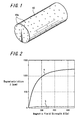
- this pressed powder molded material is temporarily sintered in the atmosphere of Ar gas with pressure of 1,08 bar (1.1 at), the temperature ranging of from 1200°C to 1250°C for 30 minutes. After that, the resultant product was sintered at the temperature ranging of from 900°C to 1100°C for 200 hours and thereby a magnetostrictive sintered material 10 having a predetermined shape shown in FIG. 1 was manufactured.
- the resultant magnetostrictive sintered material 10 is a Tb 0.3 Dy 0.7 Fe 2 alloy and magnetostrictive properties of 1200 ppm were obtained under the magnetic field less than 800 A/cm (1 kOe) as shown by the curve a in FIG. 2 .
- the magnetostrictive sintered material 10 it is possible to manufacture the magnetostrictive sintered material 10 with the arbitrary shape and the high magnetic properties at a relatively low manufacturing cost.
- the magnetostrictive sintered material 10 manufactured by this powder metallurgy method has innumerable extremely small holes 10a as shown in FIG. 1 .
- this magnetostrictive sintered material 10 was processed by the treatments described below.
- the impregnated composition material was impregnated into this magnetostrictive sintered material 10 and cured by using impregnation phenol resin (manufactured by Sumitomo Bakelite Company Limited under the trade name of "PR-9183B") as the impregnated composition material as follows.
- the magnetostrictive sintered material 10 is rinsed in the pre-treatment process. After that, this magnetostrictive sintered material 10 is set within a tank and this tank is evacuated to let an air out of the holes 10a of the magnetostrictive sintered material 10. After that, the impregnation phenol resin that is the impregnated composition material is injected into this tank and this magnetostrictive sintered material 10 is dipped into this impregnation phenol resin.
- this impregnation phenol resin is impregnated into the holes 10a of the magnetostrictive sintered material 10 by returning the tank to the atmospheric pressure.
- the magnetostrictive sintered material 10 is taken out of the tank and extra impregnation phenol resin is removed from the surface of the magnetostrictive sintered material 10 by rinsing. Thereafter, the resultant product is dried at 150°C in the air and impregnation phenol resin in the holes 10a is cured. Thus, the impregnation and curing treatment is completed.
- Impregnation phenol resin manufactured by Sumitomo Bakelite Company Limited under the trade name of "PR-9183B"
- powder (particle size thereof lies in a range of from 5 to 20 micrometers) of iron that is, iron equivalent to S15C
- This mixed impregnation phenol resin product is impregnated and cured into the holes 10a of the magnetostrictive sintered material 10 as follows.
- the magnetostrictive sintered material 10 is rinsed in the pre-treatment process. After that, this magnetostrictive sintered material 10 is set within in a tank and this tank is evacuated to let an air out of the holes 10a of the magnetostrictive sintered material 10. After that, the impregnation phenol resin in which the powder of the ferromagnetic material was dispersed is injected into this tank and this magnetostrictive sintered material 10 is dipped into the impregnation phenol resin into which the powder of the ferromagnetic material was dispersed.
- the impregnation phenol resin in which the powder of the ferromagnetic material was dispersed is impregnated into the holes 10a of this magnetostrictive sintered material 10 by returning the tank into the atmospheric pressure.
- the magnetostrictive sintered material 10 is taken out of the tank and extra impregnation phenol resin in which the powder of the ferromagnetic material was dispersed is removed from the surface of the magnetostrictive sintered material 10 by rinsing. Thereafter, the resultant product is dried at 150°C in the air and the impregnation phenol resin in which the powder of the ferromagnetic material was dispersed in the holes 10a is cured. Thus, the impregnation and curing treatment is completed.
- the magnetic permeability of the magnetostriction device in which the impregnation phenol resin in which the ferromagnetic material powder was dispersed is impregnated and cured into the holes 10a of this magnetostrictive sintered material 10 is increased approximately 5% as compared with that of the magnetostriction device in which the impregnation phenol resin in which this ferromagnetic material was dispersed is not impregnated and cured into the holes 10a of this magnetostrictive sintered material 10.
- the mechanical strength of the magnetostriction device manufactured by the powder metallurgy method can be improved and the magnetic permeability of the magnetostriction device manufactured by this powder metallurgy method also can be improved.
- the present invention is not limited thereto and phenol resin, resin in which an inorganic material such as silica is dispersed into phenol resin, epoxy based resin or acrylic resin can be used as the above-mentioned impregnated composition material.
- the present invention is not limited thereto and other suitable materials such as permalloy and magnetite can be used as the above-mentioned ferromagnetic material.
- a magnetostriction device in which an impregnated composition material is impregnated into and caked into holes of a magnetostrictive sintered material manufactured by a powder metallurgy method, wherein the impregnated composition material has a powder-like material with a high magnetic permeability dispersed therein.
- a magnetostriction device in which a magnetostrictive sintered material of Tb 0.3 Dy 0.7 Fe 2 is made of powder ground from Fe 2 Tb and Fe 2 Dy by a powder metallurgy method, an impregnated composition material being impregnated and caked into the holes of the magnetostrictive sintered material.
- the impregnated composition material is phenol resin or phenol resin, epoxy based resin or acrylic resin in which an inorganic material such as silica is dispersed.
- the impregnated composition material is impregnated into the holes of the magnetostrictive sintered material, it is possible to improve mechanical strength of this magnetostriction device.
- the magnetostriction device has the powder-like material with the high magnetic permeability dispersed into the above-mentioned impregnated composition material.
- the impregnated composition material in which the powder-like material with the high magnetic permeability is dispersed is impregnated and caked into the holes of the magnetostrictive sintered material, the mechanical strength of this magnetostriction device can be improved and the magnetic permeability thereof also can be improved.
- the mechanical strength of the magnetostriction device manufactured by the powder metallurgy method can be improved and the magnetic permeability thereof also can be improved.
Landscapes
- Engineering & Computer Science (AREA)
- Manufacturing & Machinery (AREA)
- Mechanical Engineering (AREA)
- Powder Metallurgy (AREA)
- Soft Magnetic Materials (AREA)
- Compositions Of Oxide Ceramics (AREA)
Description
- The present invention relates to a magnetostriction device for use with a magneto-machine transducer device such as a magnetostriction actuator and a magnetostriction piezoelectric transducer.
- A magnetostriction device using magnetostrictive sintered material manufactured by the powder metallurgy method has a small volume density of approximately 80% as compared with a magnetostriction device manufactured by a single crystal method or a unidirectional solidification method. The reason for this is that this magnetostrictive sintered material has holes formed thereon and that these holes occupy approximately 20% of the whole volume of the magnetostrictive sintered material.
- Therefore, the magnetostriction device using this magnetostrictive sintered material has a magnetic permeability smaller than that of the magnetostriction device manufactured by this single crystal method or the unidirectional solidification method. Furthermore, the above magnetostriction device using this magnetostrictive sintered material encounters with a disadvantage that it is weak against external force such that it is easily broken when pre-stress is applied.
- A magnetostriction device of this type is e.g. described in
US 4,152,178 . - In view of the aforesaid problem, it is an object of the present invention to provide a magnetostriction device in which mechanical strength against external force can be improved.
- It is another object of the present invention to provide a magnetostriction device in which a magnetic permeability can be improved.
- According to an aspect of the present invention, there is provided a magnetostriction device in which an impregnated composition material is impregnated into holes of a magnetostrictive sintered material manufactured by a powder metallurgy method, wherein said impregnated composition material has a powder-like material with a high magnetic permeability dispersed therein.
- Preferably, said magnetostrictive sintered material comprises Tb0.3Dy0.7Fe2 obtainable by a powder metallurgy method from powder ground from Fe2Tbx and Fe2Dy.
- Preferably, said impregnated composition material is either (a) phenol resin; or (b) phenol resin, epoxy based resin or acrylic resin in which an inorganic material such as silica is dispersed.
- Preferably, said material with a high magnetic permeability is iron, permalloy or magnetite.
- According to the present invention, since the impregnated composition material is impregnated into the holes of the magnetostrictive sintered material, it is possible to improve the mechanical strength of this magnetostriction device.
- Also, the magnetostriction device according to the present invention has the powder-like material with the high magnetic permeability dispersed into the above-mentioned impregnated composition material.
- Further, according to the present invention, since the impregnated composition material in which the powder-like material with the high magnetic permeability is dispersed is impregnated into the holes of the magnetostrictive sintered material, the mechanical strength of this magnetostriction device can be improved and the magnetic permeability thereof also can be improved.
- Furthermore, according to the present invention, the mechanical strength of the magnetostriction device manufactured by the powder metallurgy method can be improved and the magnetic permeability thereof also can be improved.
- Embodiments of the invention will now be described, by way of example only, with reference to the accompanying drawings in which:
-
FIG. 1 is a perspective view showing a magnetostriction device according to an embodiment of the present invention. -
FIG. 2 is a diagram showing examples of characteristic curves indicating measured results of magnetostrictive properties of a magnetostriction device; and -
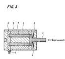
FIG. 3 is a schematic cross-sectional view showing an example of an actuator using a magnetostriction device. - A magnetostriction device that embodies the present invention will be described with reference to the drawings.
- In this embodiment, first, a magnetostrictive sintered material having a predetermined shape is formed by a powder metallurgy method similar to the related art. More specifically, Fe2Tb and Fe2Dy are ground in the atmosphere of Ar gas to produce powder of a particle size of approximately 10 µ mesh as a binary alloy of a rare earth-3d element having a large magnetic anisotropy.
- Next, after the above powder was mixed well, the resulting product is processed by a magnetic press treatment under the magnetic field ranging of from 8000 to 12000 A/cm (10 to 15 kOe) and thereby a pressed powder molded material having a predetermined shape is manufactured. In this case, it is possible to manufacture a pressed powder molded material having an arbitrary shape.
- Further, this pressed powder molded material is temporarily sintered in the atmosphere of Ar gas with pressure of 1,08 bar (1.1 at), the temperature ranging of from 1200°C to 1250°C for 30 minutes. After that, the resultant product was sintered at the temperature ranging of from 900°C to 1100°C for 200 hours and thereby a magnetostrictive sintered
material 10 having a predetermined shape shown inFIG. 1 was manufactured. - The resultant magnetostrictive
sintered material 10 is a Tb0.3Dy0.7Fe2 alloy and magnetostrictive properties of 1200 ppm were obtained under the magnetic field less than 800 A/cm (1 kOe) as shown by the curve a inFIG. 2 . - According to the embodiment of the present invention, it is possible to manufacture the magnetostrictive
sintered material 10 with the arbitrary shape and the high magnetic properties at a relatively low manufacturing cost. The magnetostrictive sinteredmaterial 10 manufactured by this powder metallurgy method has innumerable extremelysmall holes 10a as shown inFIG. 1 . - In the following examples, this magnetostrictive
sintered material 10 was processed by the treatments described below. - The impregnated composition material was impregnated into this magnetostrictive sintered
material 10 and cured by using impregnation phenol resin (manufactured by Sumitomo Bakelite Company Limited under the trade name of "PR-9183B") as the impregnated composition material as follows. - First, the magnetostrictive
sintered material 10 is rinsed in the pre-treatment process. After that, this magnetostrictivesintered material 10 is set within a tank and this tank is evacuated to let an air out of theholes 10a of the magnetostrictive sinteredmaterial 10. After that, the impregnation phenol resin that is the impregnated composition material is injected into this tank and this magnetostrictivesintered material 10 is dipped into this impregnation phenol resin. - After that, this impregnation phenol resin is impregnated into the
holes 10a of the magnetostrictive sinteredmaterial 10 by returning the tank to the atmospheric pressure. - Next, the magnetostrictive
sintered material 10 is taken out of the tank and extra impregnation phenol resin is removed from the surface of the magnetostrictive sinteredmaterial 10 by rinsing. Thereafter, the resultant product is dried at 150°C in the air and impregnation phenol resin in theholes 10a is cured. Thus, the impregnation and curing treatment is completed. - When flexural strength of the magnetostriction device in which impregnation phenol resin was impregnated and cured into the
holes 10a of the magnetostrictivesintered material 10 was measured by a three-point flexural measurement method, the flexural strength of this magnetostriction device was about 28 MPa, and it could be confirmed that the flexural strength of the magnetostriction device according to the present invention is large as compared with flexural strength of 23.4 MPa of a magnetostriction device made of a magnetostrictive sintered material in which this impregnation phenol resin is not impregnated and cured into theholes 10a. - Impregnation phenol resin (manufactured by Sumitomo Bakelite Company Limited under the trade name of "PR-9183B") is used as a impregnated composition material, and powder (particle size thereof lies in a range of from 5 to 20 micrometers) of iron (that is, iron equivalent to S15C) , which is a ferromagnetic material, is dispersed into this impregnation phenol resin with a weight ratio of "5" of impregnation phenol resin to "1" of iron powder. This mixed impregnation phenol resin product is impregnated and cured into the
holes 10a of the magnetostrictive sinteredmaterial 10 as follows. - First, the magnetostrictive
sintered material 10 is rinsed in the pre-treatment process. After that, this magnetostrictivesintered material 10 is set within in a tank and this tank is evacuated to let an air out of theholes 10a of the magnetostrictivesintered material 10. After that, the impregnation phenol resin in which the powder of the ferromagnetic material was dispersed is injected into this tank and this magnetostrictivesintered material 10 is dipped into the impregnation phenol resin into which the powder of the ferromagnetic material was dispersed. - After that, the impregnation phenol resin in which the powder of the ferromagnetic material was dispersed is impregnated into the
holes 10a of this magnetostrictivesintered material 10 by returning the tank into the atmospheric pressure. - Next, the magnetostrictive
sintered material 10 is taken out of the tank and extra impregnation phenol resin in which the powder of the ferromagnetic material was dispersed is removed from the surface of the magnetostrictive sinteredmaterial 10 by rinsing. Thereafter, the resultant product is dried at 150°C in the air and the impregnation phenol resin in which the powder of the ferromagnetic material was dispersed in theholes 10a is cured. Thus, the impregnation and curing treatment is completed. - When flexural strength of the magnetostriction device in which impregnation phenol resin in which the powder of the ferromagnetic material was dispersed was impregnated and cured into the
holes 10a of the magnetostrictive sinteredmaterial 10 was measured by a three-point flexural measurement method, the flexural strength of this magnetostriction device was about 30 MPa, and it could be confirmed that the flexural strength of the magnetostriction device according to the present invention is large as compared with flexural strength of 23.4 MPa of the magnetostriction device made of the magnetostrictive sintered material in which this impregnation phenol resin is not impregnated and cured. - Also, it could be confirmed that the magnetic permeability of the magnetostriction device in which the impregnation phenol resin in which the ferromagnetic material powder was dispersed is impregnated and cured into the
holes 10a of this magnetostrictive sinteredmaterial 10 is increased approximately 5% as compared with that of the magnetostriction device in which the impregnation phenol resin in which this ferromagnetic material was dispersed is not impregnated and cured into theholes 10a of this magnetostrictive sinteredmaterial 10. - As described above, according to the present invention, the mechanical strength of the magnetostriction device manufactured by the powder metallurgy method can be improved and the magnetic permeability of the magnetostriction device manufactured by this powder metallurgy method also can be improved.
- While the impregnation phenol resin was used as the impregnated composition material in the above-mentioned examples, the present invention is not limited thereto and phenol resin, resin in which an inorganic material such as silica is dispersed into phenol resin, epoxy based resin or acrylic resin can be used as the above-mentioned impregnated composition material.
- While the iron was used as the ferromagnetic material in the above-mentioned examples, the present invention is not limited thereto and other suitable materials such as permalloy and magnetite can be used as the above-mentioned ferromagnetic material.
- According to the present invention, there is provided a magnetostriction device in which an impregnated composition material is impregnated into and caked into holes of a magnetostrictive sintered material manufactured by a powder metallurgy method, wherein the impregnated composition material has a powder-like material with a high magnetic permeability dispersed therein.
- According to the present invention, there is provided a magnetostriction device in which a magnetostrictive sintered material of Tb0.3Dy0.7Fe2 is made of powder ground from Fe2Tb and Fe2Dy by a powder metallurgy method, an impregnated composition material being impregnated and caked into the holes of the magnetostrictive sintered material.
- Further, according to the present invention, there is provided a magnetostriction device, wherein the impregnated composition material is phenol resin or phenol resin, epoxy based resin or acrylic resin in which an inorganic material such as silica is dispersed.
- According to the present invention, since the impregnated composition material is impregnated into the holes of the magnetostrictive sintered material, it is possible to improve mechanical strength of this magnetostriction device.
- Also, the magnetostriction device according to the present invention has the powder-like material with the high magnetic permeability dispersed into the above-mentioned impregnated composition material.
- Further, according to the present invention, since the impregnated composition material in which the powder-like material with the high magnetic permeability is dispersed is impregnated and caked into the holes of the magnetostrictive sintered material, the mechanical strength of this magnetostriction device can be improved and the magnetic permeability thereof also can be improved.
- Furthermore, according to the present invention, the mechanical strength of the magnetostriction device manufactured by the powder metallurgy method can be improved and the magnetic permeability thereof also can be improved.
- Having described preferred embodiments of the invention with reference to the accompanying drawings, it is to be understood that the invention is not limited to those precise embodiments.
Claims (4)
- A magnetostriction device in which an impregnated composition material is impregnated into holes of a magnetostrictive sintered material manufactured by a powder metallurgy method, wherein said impregnated composition material has a powder-like material with a high magnetic permeability dispersed therein.
- A magnetostriction device according to claim 1, wherein said magnetostrictive sintered material comprises Tb0.3Dy0.7Fe2 obtainable by a powder metallurgy method from powder ground from Fe2Tbx and Fe2Dy.
- A magnetostriction device according to claim 1 or 2, wherein said impregnated composition material is either:(a) phenol resin; or(b) phenol resin, epoxy based resin or acrylic resin in which an inorganic material such as silica is dispersed.
- A magnetostriction device according to claim 1, 2 or 3, wherein said material with a high magnetic permeability is iron, permalloy or magnetite.
Applications Claiming Priority (2)
| Application Number | Priority Date | Filing Date | Title |
|---|---|---|---|
| JP2003369396 | 2003-10-29 | ||
| JP2003369396A JP2005136091A (en) | 2003-10-29 | 2003-10-29 | Magnetostrictive element |
Publications (3)
| Publication Number | Publication Date |
|---|---|
| EP1528610A2 EP1528610A2 (en) | 2005-05-04 |
| EP1528610A3 EP1528610A3 (en) | 2007-04-18 |
| EP1528610B1 true EP1528610B1 (en) | 2008-11-19 |
Family
ID=34420177
Family Applications (1)
| Application Number | Title | Priority Date | Filing Date |
|---|---|---|---|
| EP04256678A Expired - Lifetime EP1528610B1 (en) | 2003-10-29 | 2004-10-28 | Magnetostriction device with impregnated composite material |
Country Status (6)
| Country | Link |
|---|---|
| US (2) | US20050092131A1 (en) |
| EP (1) | EP1528610B1 (en) |
| JP (1) | JP2005136091A (en) |
| KR (1) | KR20050040717A (en) |
| CN (1) | CN100387745C (en) |
| DE (1) | DE602004017824D1 (en) |
Families Citing this family (7)
| Publication number | Priority date | Publication date | Assignee | Title |
|---|---|---|---|---|
| JP2007281009A (en) * | 2006-04-03 | 2007-10-25 | Yaskawa Electric Corp | Functional composite materials |
| DE102011052528B3 (en) * | 2011-08-09 | 2013-02-14 | Eto Magnetic Gmbh | Actuator device and method of manufacturing an actuator device |
| JP5969750B2 (en) * | 2011-10-14 | 2016-08-17 | 日東電工株式会社 | Rare earth permanent magnet manufacturing method |
| JP5969783B2 (en) * | 2012-03-12 | 2016-08-17 | 日東電工株式会社 | Rare earth permanent magnet manufacturing method |
| JP5969782B2 (en) * | 2012-03-12 | 2016-08-17 | 日東電工株式会社 | Rare earth permanent magnet manufacturing method |
| JP5969781B2 (en) * | 2012-03-12 | 2016-08-17 | 日東電工株式会社 | Rare earth permanent magnet manufacturing method |
| CN104550944B (en) * | 2013-10-11 | 2017-05-03 | 有研稀土新材料股份有限公司 | Preparation method of composite rare earth magnetostriction material |
Family Cites Families (15)
| Publication number | Priority date | Publication date | Assignee | Title |
|---|---|---|---|---|
| US2490273A (en) * | 1947-11-18 | 1949-12-06 | Standard Oil Dev Co | Structure for magnetostriction transducers |
| DE1230576B (en) * | 1964-03-19 | 1966-12-15 | Prakla Gmbh | Cylindrical magnetostrictive sound receiver |
| US4152178A (en) * | 1978-01-24 | 1979-05-01 | The United States Of America As Represented By The United States Department Of Energy | Sintered rare earth-iron Laves phase magnetostrictive alloy product and preparation thereof |
| JPH01180943A (en) * | 1988-01-08 | 1989-07-18 | Komatsu Ltd | Sintered magnetostrictive alloy |
| US5792284A (en) * | 1991-05-22 | 1998-08-11 | Fox Technology Kb | Magnetostrictive powder composite and methods for the manufacture thereof |
| JP3119707B2 (en) * | 1991-12-12 | 2000-12-25 | ティーディーケイ株式会社 | Magnetostrictive element |
| JPH0762404A (en) * | 1993-08-25 | 1995-03-07 | Tokin Corp | Magnetostriction material and production thereof |
| US5628569A (en) * | 1993-10-18 | 1997-05-13 | Kabushiki Kaisha Sankyo Seiki Seisakusho | Fluid bearing unit and manufactured method thereof |
| JP3452210B2 (en) * | 1994-04-19 | 2003-09-29 | Tdk株式会社 | Manufacturing method of magnetostrictive material |
| JPH08264855A (en) * | 1995-03-24 | 1996-10-11 | Tokin Corp | Magnetostrictive material and manufacture thereof |
| JPH0955550A (en) * | 1995-08-15 | 1997-02-25 | Tokai Univ | Composite magnetostrictive material |
| JPH10242543A (en) * | 1997-02-27 | 1998-09-11 | Seiko Epson Corp | Resin bonded type magnetostrictive material |
| US6413624B1 (en) * | 1999-03-09 | 2002-07-02 | International Superconductivity Technology Center | Oxide superconductor and process for producing same |
| CN100442401C (en) * | 2001-02-07 | 2008-12-10 | Tdk株式会社 | magnetostrictive material |
| KR100405960B1 (en) * | 2001-10-12 | 2003-11-14 | 한국과학기술원 | Method for Manufacturing of Polymer Composite with Directionally Solidified Giant Magnetostrictive Material |
-
2003
- 2003-10-29 JP JP2003369396A patent/JP2005136091A/en active Pending
-
2004
- 2004-10-14 US US10/964,934 patent/US20050092131A1/en not_active Abandoned
- 2004-10-20 KR KR1020040084036A patent/KR20050040717A/en not_active Withdrawn
- 2004-10-28 DE DE602004017824T patent/DE602004017824D1/en not_active Expired - Lifetime
- 2004-10-28 EP EP04256678A patent/EP1528610B1/en not_active Expired - Lifetime
- 2004-10-29 CN CNB2004100898942A patent/CN100387745C/en not_active Expired - Fee Related
-
2006
- 2006-05-30 US US11/443,403 patent/US7488369B2/en not_active Expired - Fee Related
Also Published As
| Publication number | Publication date |
|---|---|
| US20060213325A1 (en) | 2006-09-28 |
| KR20050040717A (en) | 2005-05-03 |
| US20050092131A1 (en) | 2005-05-05 |
| EP1528610A3 (en) | 2007-04-18 |
| US7488369B2 (en) | 2009-02-10 |
| DE602004017824D1 (en) | 2009-01-02 |
| CN100387745C (en) | 2008-05-14 |
| CN1611624A (en) | 2005-05-04 |
| EP1528610A2 (en) | 2005-05-04 |
| JP2005136091A (en) | 2005-05-26 |
Similar Documents
| Publication | Publication Date | Title |
|---|---|---|
| Cai et al. | Dielectric, ferroelectric, magnetic, and magnetoelectric properties of multiferroic laminated composites | |
| KR20160135236A (en) | Soft magnetic molded body, magnetic core, and magnetic sheet | |
| CN105359229A (en) | Anisotropic rare earths-free matrix-bonded high-performance permanent magnet having a nanocristalline structure, and method for production thereof | |
| US20050217759A1 (en) | Magnetically soft powder composite material, method for manufacturing same, and its use | |
| EP1528610B1 (en) | Magnetostriction device with impregnated composite material | |
| US5792284A (en) | Magnetostrictive powder composite and methods for the manufacture thereof | |
| CN103305743A (en) | Method for preparing pure iron and iron-phosphorus magnetically soft alloy product through powder metallurgy process | |
| Guo et al. | Effective magnetostriction and magnetomechanical coupling of Terfenol-D composites | |
| JP2008258463A (en) | Permanent magnet material, permanent magnet using the same, and manufacturing method thereof | |
| KR100405960B1 (en) | Method for Manufacturing of Polymer Composite with Directionally Solidified Giant Magnetostrictive Material | |
| KR100302583B1 (en) | Magnetostrictive Tb-Dy-Fe Alloy Composites and Manufacture Thereof | |
| JPH10242543A (en) | Resin bonded type magnetostrictive material | |
| JPS5923446B2 (en) | Plastic magnets and their manufacturing method | |
| Zhao et al. | Magnetostrictive and magnetic properties of Tb0. 29Dy0. 48Ho0. 23Fe1. 9 fiber/epoxy composites | |
| Lv et al. | Magnetomechanical properties of epoxy-bonded (Tb0. 3Dy0. 7) 1− xPrxFe1. 55 (0⩽ x⩽ 0.4) pseudo-1–3 magnetostrictive composites | |
| JPH06507676A (en) | Magnetostrictive powder composite material and its manufacturing method | |
| JP2012079822A (en) | Production method of rare earth anisotropic magnet | |
| JPH06330102A (en) | Method for compacting magnet powder in magnetic field and manufacture of magnet | |
| JPH05217778A (en) | Production of fe-ni alloy dust core | |
| JPH0715124B2 (en) | Method for producing magnetic composite material having excellent magnetic properties | |
| JPH04247605A (en) | Manufacture of r-t-b anisotropic bond magnet | |
| JP4336429B2 (en) | magnet | |
| CN117809963A (en) | Method for producing anisotropic magnetic powder compact and bonded magnet | |
| TAKEUCHI et al. | Characterization of giant magnetostrictive composite | |
| JPH03129802A (en) | Resin bonded rare-earth magnet |
Legal Events
| Date | Code | Title | Description |
|---|---|---|---|
| PUAI | Public reference made under article 153(3) epc to a published international application that has entered the european phase |
Free format text: ORIGINAL CODE: 0009012 |
|
| AK | Designated contracting states |
Kind code of ref document: A2 Designated state(s): AT BE BG CH CY CZ DE DK EE ES FI FR GB GR HU IE IT LI LU MC NL PL PT RO SE SI SK TR |
|
| AX | Request for extension of the european patent |
Extension state: AL HR LT LV MK |
|
| PUAL | Search report despatched |
Free format text: ORIGINAL CODE: 0009013 |
|
| AK | Designated contracting states |
Kind code of ref document: A3 Designated state(s): AT BE BG CH CY CZ DE DK EE ES FI FR GB GR HU IE IT LI LU MC NL PL PT RO SE SI SK TR |
|
| AX | Request for extension of the european patent |
Extension state: AL HR LT LV MK |
|
| 17P | Request for examination filed |
Effective date: 20070925 |
|
| 17Q | First examination report despatched |
Effective date: 20071026 |
|
| AKX | Designation fees paid |
Designated state(s): DE FR GB |
|
| GRAP | Despatch of communication of intention to grant a patent |
Free format text: ORIGINAL CODE: EPIDOSNIGR1 |
|
| GRAS | Grant fee paid |
Free format text: ORIGINAL CODE: EPIDOSNIGR3 |
|
| GRAA | (expected) grant |
Free format text: ORIGINAL CODE: 0009210 |
|
| AK | Designated contracting states |
Kind code of ref document: B1 Designated state(s): DE FR GB |
|
| REG | Reference to a national code |
Ref country code: GB Ref legal event code: FG4D |
|
| REF | Corresponds to: |
Ref document number: 602004017824 Country of ref document: DE Date of ref document: 20090102 Kind code of ref document: P |
|
| PLBE | No opposition filed within time limit |
Free format text: ORIGINAL CODE: 0009261 |
|
| STAA | Information on the status of an ep patent application or granted ep patent |
Free format text: STATUS: NO OPPOSITION FILED WITHIN TIME LIMIT |
|
| 26N | No opposition filed |
Effective date: 20090820 |
|
| PGFP | Annual fee paid to national office [announced via postgrant information from national office to epo] |
Ref country code: FR Payment date: 20101104 Year of fee payment: 7 |
|
| PGFP | Annual fee paid to national office [announced via postgrant information from national office to epo] |
Ref country code: DE Payment date: 20101022 Year of fee payment: 7 |
|
| PGFP | Annual fee paid to national office [announced via postgrant information from national office to epo] |
Ref country code: GB Payment date: 20101021 Year of fee payment: 7 |
|
| GBPC | Gb: european patent ceased through non-payment of renewal fee |
Effective date: 20111028 |
|
| REG | Reference to a national code |
Ref country code: FR Ref legal event code: ST Effective date: 20120629 |
|
| PG25 | Lapsed in a contracting state [announced via postgrant information from national office to epo] |
Ref country code: DE Free format text: LAPSE BECAUSE OF NON-PAYMENT OF DUE FEES Effective date: 20120501 |
|
| REG | Reference to a national code |
Ref country code: DE Ref legal event code: R119 Ref document number: 602004017824 Country of ref document: DE Effective date: 20120501 |
|
| PG25 | Lapsed in a contracting state [announced via postgrant information from national office to epo] |
Ref country code: FR Free format text: LAPSE BECAUSE OF NON-PAYMENT OF DUE FEES Effective date: 20111102 Ref country code: GB Free format text: LAPSE BECAUSE OF NON-PAYMENT OF DUE FEES Effective date: 20111028 |