EP1528607B1 - Module actionneur - Google Patents
Module actionneur Download PDFInfo
- Publication number
- EP1528607B1 EP1528607B1 EP04105087A EP04105087A EP1528607B1 EP 1528607 B1 EP1528607 B1 EP 1528607B1 EP 04105087 A EP04105087 A EP 04105087A EP 04105087 A EP04105087 A EP 04105087A EP 1528607 B1 EP1528607 B1 EP 1528607B1
- Authority
- EP
- European Patent Office
- Prior art keywords
- actuator
- piezoelectric
- actuator module
- housing
- magnetostrictive element
- Prior art date
- Legal status (The legal status is an assumption and is not a legal conclusion. Google has not performed a legal analysis and makes no representation as to the accuracy of the status listed.)
- Expired - Lifetime
Links
- 239000000446 fuel Substances 0.000 claims description 14
- 238000002347 injection Methods 0.000 claims description 11
- 239000007924 injection Substances 0.000 claims description 11
- 238000007789 sealing Methods 0.000 claims description 6
- 238000002485 combustion reaction Methods 0.000 claims description 4
- 230000004323 axial length Effects 0.000 claims description 2
- 150000001875 compounds Chemical class 0.000 claims 5
- 238000004382 potting Methods 0.000 description 7
- 238000005538 encapsulation Methods 0.000 description 6
- 239000000463 material Substances 0.000 description 3
- 230000017525 heat dissipation Effects 0.000 description 2
- 238000004519 manufacturing process Methods 0.000 description 2
- 230000002238 attenuated effect Effects 0.000 description 1
- 230000005540 biological transmission Effects 0.000 description 1
- 238000005266 casting Methods 0.000 description 1
- 238000013016 damping Methods 0.000 description 1
- 230000001419 dependent effect Effects 0.000 description 1
- 239000012777 electrically insulating material Substances 0.000 description 1
- 238000000034 method Methods 0.000 description 1
- 230000000087 stabilizing effect Effects 0.000 description 1
- 238000003466 welding Methods 0.000 description 1
Images

Classifications
-
- H—ELECTRICITY
- H10—SEMICONDUCTOR DEVICES; ELECTRIC SOLID-STATE DEVICES NOT OTHERWISE PROVIDED FOR
- H10N—ELECTRIC SOLID-STATE DEVICES NOT OTHERWISE PROVIDED FOR
- H10N30/00—Piezoelectric or electrostrictive devices
- H10N30/80—Constructional details
- H10N30/88—Mounts; Supports; Enclosures; Casings
- H10N30/886—Additional mechanical prestressing means, e.g. springs
-
- F—MECHANICAL ENGINEERING; LIGHTING; HEATING; WEAPONS; BLASTING
- F02—COMBUSTION ENGINES; HOT-GAS OR COMBUSTION-PRODUCT ENGINE PLANTS
- F02B—INTERNAL-COMBUSTION PISTON ENGINES; COMBUSTION ENGINES IN GENERAL
- F02B75/00—Other engines
- F02B75/12—Other methods of operation
- F02B2075/125—Direct injection in the combustion chamber for spark ignition engines, i.e. not in pre-combustion chamber
-
- F—MECHANICAL ENGINEERING; LIGHTING; HEATING; WEAPONS; BLASTING
- F02—COMBUSTION ENGINES; HOT-GAS OR COMBUSTION-PRODUCT ENGINE PLANTS
- F02M—SUPPLYING COMBUSTION ENGINES IN GENERAL WITH COMBUSTIBLE MIXTURES OR CONSTITUENTS THEREOF
- F02M51/00—Fuel-injection apparatus characterised by being operated electrically
- F02M51/06—Injectors peculiar thereto with means directly operating the valve needle
- F02M51/0603—Injectors peculiar thereto with means directly operating the valve needle using piezoelectric or magnetostrictive operating means
-
- Y—GENERAL TAGGING OF NEW TECHNOLOGICAL DEVELOPMENTS; GENERAL TAGGING OF CROSS-SECTIONAL TECHNOLOGIES SPANNING OVER SEVERAL SECTIONS OF THE IPC; TECHNICAL SUBJECTS COVERED BY FORMER USPC CROSS-REFERENCE ART COLLECTIONS [XRACs] AND DIGESTS
- Y02—TECHNOLOGIES OR APPLICATIONS FOR MITIGATION OR ADAPTATION AGAINST CLIMATE CHANGE
- Y02T—CLIMATE CHANGE MITIGATION TECHNOLOGIES RELATED TO TRANSPORTATION
- Y02T10/00—Road transport of goods or passengers
- Y02T10/10—Internal combustion engine [ICE] based vehicles
- Y02T10/12—Improving ICE efficiencies
Definitions
- the invention is based on a piezoelectric or magnetostrictive actuator module according to the preamble of claim 1.
- a piezoelectric actuator is known, which is used in particular for actuating control valves or injectors on internal combustion engines in motor vehicles, the actuator having a piezoelectric actuator body, in particular in the form of a multilayer laminate of stacked layers of piezoelectric material and intervening metallic or electrically conductive layers.
- One of the end faces of the actuator body is fixed to an actuator base.
- the actuator body is surrounded by a module wall while maintaining a gap, wherein the gap is filled with an elastic or plastic, electrically insulating material good thermal conductivity.
- a disadvantage of the from the DE 198 56 186 A1 known actuator are in particular the high production costs and high production costs. These are due to the fact that the actuator is biased by a spring band and the Aktorum mousseung therefore must be done with a relatively low-viscosity material in order to surround the actuator module on the one hand everywhere without cavities and on the other to obtain the elasticity. The requirements for the Umspritzungsmaterial are therefore very high, whereby the material is expensive.
- a piezoelectric actuator for an actuator which is incorporated in a drive housing, wherein the actuator has an actuator stack, which is comprised of a hollow cylindrical spring element and an actuator shell arranged therein; the spring element is clamped together with the actuator stack between an actuator cover and an actuator base; an elastic mass fills the gaps between the actuator housing, the spring element and the actuator shell.
- the elastic mass is electrically insulating, elastic, temperature resistant and resistant to fuels. Furthermore, the elastic mass damps the movement between the spring element and the actuator shell, wherein the movement is attenuated reinforced when between the actuator stack and the actuator shell, a narrow gap is formed, in which the elastic mass is introduced.
- the damping z. B. adjustable over the length of the gap or on the degree of filling of the gap with elastic mass.
- WO 01/91197 A1 discloses a piezoelectric actuator in which a piezoelectric element is provided for acting on an actuating element with a tensile or compressive force.
- a sleeve is fastened to a foot part on which the piezoelectric element is fastened and via which the piezoelement is centered under a mechanical pretension in a housing, which encloses the piezoelectric element in a mechanically stabilizing manner, at least in partial regions, electrically insulated from it.
- a hollow profile having a centering ring can be used, the so are designed to include an air volume and is compressible in heat changes.
- DE 101 62 045 A1 discloses a device for translating a deflection of an actuator, in particular for an injection valve.
- the device essentially has two pistons which can be displaced relative to one another and are coupled to one another via a transmission chamber without play.
- One of the two pistons is biased by an externally disposed spring to an initial position.
- the arrangement of the spring outside the piston a reduction of the dead volume between the piston is possible and the operation of the transmitter device is improved.
- the inventively designed actuator module with the features of the main claim has the advantage that the actuator is cast directly to the actuator housing.
- the casting has a high thermal conductivity, which ensures the thermal connection of the actuator module to the actuator housing.
- a multi-layer encapsulation is not necessary.
- Such an actuator module is simple and inexpensive to produce with little effort.
- the actuator module is preassembled and then filled with at least one bore in the actuator base in one operation with the potting.
- the at least one bore can be closed in a simple manner after filling with a pressed-in ball.
- FIG. 1 is to better understand the in Fig. 2 illustrated inventive measures represented an actuator module 2 according to the prior art.
- This in Fig. 1 illustrated actuator module 2 serves z. B. for actuating a fuel injection valve 1, which is particularly suitable for the direct injection of fuel into the combustion chamber of a mixture-compressing, self-or spark-ignited internal combustion engine.
- the actuator module 2 is in Fig. 1 to improve clarity of the inventive measures shown installed in a fuel injector 1.
- the fuel injection valve 1 comprises a valve housing 20 through which fuel is supplied through a central fuel supply 21 and guided in the direction of a sealing seat, not shown.
- the fuel injection valve 1 can be designed in any way. Downstream of the actuator module 2, an unspecified hydraulic coupler 22 may be arranged for Hubübersville the actuator module 2.
- the actuator module 2 consists of a piezoelectric or magnetostrictive element 3. This can be carried out either monolithically or consist of disc-shaped piezoelectric or magnetostrictive layers, which can be glued together.
- the actuator module 2 is in with Fig. 1 invisible contact pins provided for contacting.
- the contact pins and the piezoelectric or magnetostrictive element 3 are surrounded by an encapsulation 5, preferably made of plastic, in which the contact pins are embedded.
- the encapsulation 5 serves to dissipate the heat generated by the piezoelectric or magnetostrictive element 3 during operation.
- the piezoelectric or magnetostrictive element 3 is prestressed and provided with an actuator head 6 and an actuator foot 7.
- the bias voltage is applied by a tube spring 8, which is preferably welded to the actuator head 6 and the actuator base 7.
- a first, inner gap 10 is formed, which prevents the heat dissipation from the encapsulation 5.
- a second, outer gap 11 is formed between an actuator housing 12 and the tube spring 8, which prevents heat dissipation from the tube spring 8.
- the invention proposes to provide the actuator module 2 with a single potting 16, which envelops the piezoelectric or magnetostrictive element 3, the tube spring 8 and the actuator housing 12 fills and can be introduced in a single step. This causes the thermal connection of the piezoelectric or magnetostrictive element 3 directly to the actuator housing 12.
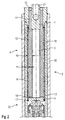
- An embodiment of a correspondingly designed actuator module 2 is in Fig. 2 in the same representation as in Fig. 1 shown.
- the introduction of the potting 16 takes place via at least one bore 14 in the actuator base 7, which is closed after filling by a pressed ball 15.
- a plurality of holes 14 are provided, which ensures that the potting 16 penetrates evenly and also the gap 11 reliably filled.
- the potting 16 also fills the actuator housing 12 completely up to a certain axial length.
- a method for assembling an actuator module 2 designed according to the invention takes place in the following steps:
- the tube spring 8 is welded to the actuator base 7.
- the piezoelectric or magnetostrictive element 3 is inserted into the tube spring 8.
- the piezoelectric or magnetostrictive element 3 can be centered in the tube spring 8 and at the same time protected against damage during assembly. Furthermore, it is prevented by the ring 18 that the piezoelectric or magnetostrictive element 3 is crazy in the introduction of the potting 16 from its central position.
- ring is provided on the actuator base 7. This requires recesses which are congruent with the holes 14 in order not to hinder the filling of the actuator module 2. If the actuator head 6 is placed on the ring 18, it is also welded to the tube spring 8.
- the preassembled, not encapsulated actuator module 2 is inserted into the actuator housing 12.
- the actuator housing 12 and the gap 11 and a gap 19 between the piezoelectric or magnetostrictive element 3 and the tube spring 8 is provided with the encapsulation 16.
- the finished encapsulated actuator module can then be installed with the hydraulic coupler 22 in the valve housing 20 of the fuel injection valve 1.
- the invention is not limited to the illustrated embodiment and in particular in a Variety of designs of fuel injection valves applicable. Also, all features of the embodiment can be combined with each other.
Landscapes
- Fuel-Injection Apparatus (AREA)
Claims (4)
- Module d'actionneur (2) notamment pour actionner des injecteurs de carburant (1) destinés à des installations d'injection de carburant équipant des moteurs à combustion interne comprenant au moins un élément piézo-électrique ou magnétostrictif (3),
le module d'actionneur (2) étant précontraint par un ressort tubulaire (8) et encapsulé dans un boîtier d'actionneur (12),
caractérisé en ce que
le boîtier d'actionneur (12) est rempli d'une unique matière coulée (16) pour coupler de manière thermique l'élément piézo-électrique ou magnétostrictif (3) directement au boîtier d'actionneur (12), cette matière coulée remplissant l'espace intermédiaire (19) entre l'élément piézo-électrique ou magnétostrictif (3) et le ressort tubulaire (8) ainsi qu'un intervalle (11) entre le ressort tubulaire (8) et le boîtier d'actionneur (12),
la matière coulée (16) étant introduite dans le boîtier d'actionneur (12) à travers au moins un perçage (14) réalisé dans le pied (7) de l'actionneur, et
la tête (6) de l'actionneur comporte une bague (18) traversée par l'élément piézo-électrique ou magnétostrictif (3), et le pied (7) de l'actionneur comporte également une bague munie de dégagements qui coïncident au moins avec un perçage (14). - Module d'actionneur selon la revendication 1,
caractérisé en ce qu'
au moins le perçage (14) est fermé par une bille (15) enfoncée de force. - Module d'actionneur selon la revendication 1 ou 2,
caractérisé en ce que
le module d'actionneur (2) est couplé thermiquement au boîtier d'actionneur (12) par l'intermédiaire de la matière coulée (16). - Module d'actionneur selon les revendications 1 à 3,
caractérisé en ce que
la matière coulée (16) occupe toute la longueur axiale du module d'actionneur (2).
Applications Claiming Priority (2)
| Application Number | Priority Date | Filing Date | Title |
|---|---|---|---|
| DE10350062A DE10350062A1 (de) | 2003-10-27 | 2003-10-27 | Aktormodul und Verfahren zu dessen Herstellung |
| DE10350062 | 2003-10-27 |
Publications (3)
| Publication Number | Publication Date |
|---|---|
| EP1528607A2 EP1528607A2 (fr) | 2005-05-04 |
| EP1528607A3 EP1528607A3 (fr) | 2005-08-10 |
| EP1528607B1 true EP1528607B1 (fr) | 2008-12-10 |
Family
ID=34399562
Family Applications (1)
| Application Number | Title | Priority Date | Filing Date |
|---|---|---|---|
| EP04105087A Expired - Lifetime EP1528607B1 (fr) | 2003-10-27 | 2004-10-15 | Module actionneur |
Country Status (2)
| Country | Link |
|---|---|
| EP (1) | EP1528607B1 (fr) |
| DE (2) | DE10350062A1 (fr) |
Families Citing this family (2)
| Publication number | Priority date | Publication date | Assignee | Title |
|---|---|---|---|---|
| DE102010015171A1 (de) * | 2010-04-16 | 2011-10-20 | Fraunhofer-Gesellschaft zur Förderung der angewandten Forschung e.V. | Piezoelektrisches Aktormodul sowie piezoelektrischer Aktor mit einem solchen piezoelektrischen Aktormodul und Herstellungsverfahren für diese |
| DE102014215327A1 (de) * | 2014-08-04 | 2016-02-04 | Continental Automotive Gmbh | Piezoaktor für einen Kraftstoffinjektor und Kraftstoffinjektor |
Family Cites Families (8)
| Publication number | Priority date | Publication date | Assignee | Title |
|---|---|---|---|---|
| NL8105502A (nl) * | 1981-12-08 | 1983-07-01 | Philips Nv | Werkwijze voor het vervaardigen van een piezo-elektrische inrichting alsmede een inrichting vervaardigd volgens deze werkwijze. |
| DE19702066C2 (de) * | 1997-01-22 | 1998-10-29 | Daimler Benz Ag | Piezoelektrischer Injektor für Kraftstoffeinspritzanlagen von Brennkraftmaschinen |
| DE19719364A1 (de) * | 1997-05-07 | 1998-11-12 | Ruediger Ufermann | Common-Rail-Piezo-Injektor hoher Steifigkeit |
| DE19818068A1 (de) * | 1998-04-22 | 1999-10-28 | Siemens Ag | Piezoelektronischer Aktor für einen Stellantrieb |
| DE19914411A1 (de) * | 1999-03-30 | 2000-10-12 | Bosch Gmbh Robert | Piezoelektrischer Aktor |
| DE10025997A1 (de) * | 2000-05-25 | 2001-12-06 | Bosch Gmbh Robert | Piezoaktor |
| DE10035168A1 (de) * | 2000-07-19 | 2002-02-07 | Siemens Ag | Stellantrieb, Ventil sowie Verfahren zum Herstellen eines Stellantriebs |
| DE10162045B4 (de) * | 2001-12-17 | 2005-06-23 | Siemens Ag | Vorrichtung zum Übersetzen einer Auslenkung eines Aktors, insbesondere für ein Einspritzventil |
-
2003
- 2003-10-27 DE DE10350062A patent/DE10350062A1/de not_active Withdrawn
-
2004
- 2004-10-15 DE DE502004008631T patent/DE502004008631D1/de not_active Expired - Lifetime
- 2004-10-15 EP EP04105087A patent/EP1528607B1/fr not_active Expired - Lifetime
Also Published As
| Publication number | Publication date |
|---|---|
| DE10350062A1 (de) | 2005-05-25 |
| EP1528607A3 (fr) | 2005-08-10 |
| EP1528607A2 (fr) | 2005-05-04 |
| DE502004008631D1 (de) | 2009-01-22 |
Similar Documents
| Publication | Publication Date | Title |
|---|---|---|
| EP0954037B1 (fr) | Dispositif piézoélectrique pour organe d'actionnement | |
| EP1082567B1 (fr) | Actionneur piezoelectrique | |
| EP1115971B1 (fr) | Soupape d'injection de carburant | |
| EP1901360B1 (fr) | Module de piezoactionneur doté d'un piezoactionneur gainé | |
| DE10148594A1 (de) | Brennstoffeinspritzventil | |
| EP1474603A1 (fr) | Soupape d'injection de carburant | |
| EP1714024B1 (fr) | Partie de systeme de carburant pourvue d'un passe-cable | |
| DE19906467A1 (de) | Injektor mit einem Piezo-Mehrlagenaktor | |
| EP1456526B1 (fr) | Soupape d'injection de carburant | |
| EP1528607B1 (fr) | Module actionneur | |
| DE10360451B4 (de) | Brennstoffeinspritzventil | |
| EP1519036B1 (fr) | Injecteur de carburant | |
| EP1939950B1 (fr) | Actionneur piézoélectrique | |
| EP1432908B1 (fr) | Soupape d'injection de carburant | |
| EP1190168B1 (fr) | Actionneur | |
| EP1431568A2 (fr) | Soupape d'injection de carburant | |
| DE10040239B4 (de) | Geräuschgedämpfte Aktoreinheit | |
| EP1528606B1 (fr) | Module actionneur | |
| DE102005016461A1 (de) | Brennstoffeinspritzventil | |
| DE10310787A1 (de) | Rohrfeder für Aktor und Verfahren zur Montage der Rohrfeder | |
| DE10321694A1 (de) | Aktormodul | |
| DE19947071B4 (de) | Geräuschgedämpfte Aktoreinheit | |
| EP1452729B1 (fr) | Injecteur de carburant | |
| DE102006014768A1 (de) | Piezoelektrischer Aktor mit ringförmigem Aktorstapel und Injektor für eine Brennkraftmaschine mit ringförmigem Piezoaktor | |
| DE19939132A1 (de) | Brennstoffeinspritzventil |
Legal Events
| Date | Code | Title | Description |
|---|---|---|---|
| PUAI | Public reference made under article 153(3) epc to a published international application that has entered the european phase |
Free format text: ORIGINAL CODE: 0009012 |
|
| AK | Designated contracting states |
Kind code of ref document: A2 Designated state(s): AT BE BG CH CY CZ DE DK EE ES FI FR GB GR HU IE IT LI LU MC NL PL PT RO SE SI SK TR |
|
| AX | Request for extension of the european patent |
Extension state: AL HR LT LV MK |
|
| PUAL | Search report despatched |
Free format text: ORIGINAL CODE: 0009013 |
|
| AK | Designated contracting states |
Kind code of ref document: A3 Designated state(s): AT BE BG CH CY CZ DE DK EE ES FI FR GB GR HU IE IT LI LU MC NL PL PT RO SE SI SK TR |
|
| AX | Request for extension of the european patent |
Extension state: AL HR LT LV MK |
|
| 17P | Request for examination filed |
Effective date: 20060210 |
|
| AKX | Designation fees paid |
Designated state(s): DE FR GB IT |
|
| 17Q | First examination report despatched |
Effective date: 20060316 |
|
| GRAP | Despatch of communication of intention to grant a patent |
Free format text: ORIGINAL CODE: EPIDOSNIGR1 |
|
| RTI1 | Title (correction) |
Free format text: ACTUATOR MODULE |
|
| GRAS | Grant fee paid |
Free format text: ORIGINAL CODE: EPIDOSNIGR3 |
|
| GRAA | (expected) grant |
Free format text: ORIGINAL CODE: 0009210 |
|
| AK | Designated contracting states |
Kind code of ref document: B1 Designated state(s): DE FR GB IT |
|
| REG | Reference to a national code |
Ref country code: GB Ref legal event code: FG4D Free format text: NOT ENGLISH |
|
| REF | Corresponds to: |
Ref document number: 502004008631 Country of ref document: DE Date of ref document: 20090122 Kind code of ref document: P |
|
| PLBE | No opposition filed within time limit |
Free format text: ORIGINAL CODE: 0009261 |
|
| STAA | Information on the status of an ep patent application or granted ep patent |
Free format text: STATUS: NO OPPOSITION FILED WITHIN TIME LIMIT |
|
| 26N | No opposition filed |
Effective date: 20090911 |
|
| PG25 | Lapsed in a contracting state [announced via postgrant information from national office to epo] |
Ref country code: IT Free format text: LAPSE BECAUSE OF FAILURE TO SUBMIT A TRANSLATION OF THE DESCRIPTION OR TO PAY THE FEE WITHIN THE PRESCRIBED TIME-LIMIT Effective date: 20081210 |
|
| PGFP | Annual fee paid to national office [announced via postgrant information from national office to epo] |
Ref country code: GB Payment date: 20141024 Year of fee payment: 11 Ref country code: DE Payment date: 20141208 Year of fee payment: 11 Ref country code: FR Payment date: 20141021 Year of fee payment: 11 |
|
| REG | Reference to a national code |
Ref country code: DE Ref legal event code: R119 Ref document number: 502004008631 Country of ref document: DE |
|
| GBPC | Gb: european patent ceased through non-payment of renewal fee |
Effective date: 20151015 |
|
| PG25 | Lapsed in a contracting state [announced via postgrant information from national office to epo] |
Ref country code: DE Free format text: LAPSE BECAUSE OF NON-PAYMENT OF DUE FEES Effective date: 20160503 Ref country code: GB Free format text: LAPSE BECAUSE OF NON-PAYMENT OF DUE FEES Effective date: 20151015 |
|
| REG | Reference to a national code |
Ref country code: FR Ref legal event code: ST Effective date: 20160630 |
|
| PG25 | Lapsed in a contracting state [announced via postgrant information from national office to epo] |
Ref country code: FR Free format text: LAPSE BECAUSE OF NON-PAYMENT OF DUE FEES Effective date: 20151102 |