EP1528511A1 - Verschiebung eines virtuellen Gliederobjekts in einer virtuellen Umgebung unter Vermeidung von Kollisionen zwischen dem Gliederobjekt und der Umgebung - Google Patents
Verschiebung eines virtuellen Gliederobjekts in einer virtuellen Umgebung unter Vermeidung von Kollisionen zwischen dem Gliederobjekt und der Umgebung Download PDFInfo
- Publication number
- EP1528511A1 EP1528511A1 EP04292230A EP04292230A EP1528511A1 EP 1528511 A1 EP1528511 A1 EP 1528511A1 EP 04292230 A EP04292230 A EP 04292230A EP 04292230 A EP04292230 A EP 04292230A EP 1528511 A1 EP1528511 A1 EP 1528511A1
- Authority
- EP
- European Patent Office
- Prior art keywords
- articulated object
- vector
- articulated
- environment
- global
- Prior art date
- Legal status (The legal status is an assumption and is not a legal conclusion. Google has not performed a legal analysis and makes no representation as to the accuracy of the status listed.)
- Granted
Links
Images




Classifications
-
- G—PHYSICS
- G06—COMPUTING OR CALCULATING; COUNTING
- G06T—IMAGE DATA PROCESSING OR GENERATION, IN GENERAL
- G06T13/00—Animation
- G06T13/20—Three-dimensional [3D] animation
- G06T13/40—Three-dimensional [3D] animation of characters, e.g. humans, animals or virtual beings
-
- G—PHYSICS
- G06—COMPUTING OR CALCULATING; COUNTING
- G06T—IMAGE DATA PROCESSING OR GENERATION, IN GENERAL
- G06T19/00—Manipulating three-dimensional [3D] models or images for computer graphics
- G06T19/20—Editing of three-dimensional [3D] images, e.g. changing shapes or colours, aligning objects or positioning parts
-
- G—PHYSICS
- G06—COMPUTING OR CALCULATING; COUNTING
- G06T—IMAGE DATA PROCESSING OR GENERATION, IN GENERAL
- G06T2210/00—Indexing scheme for image generation or computer graphics
- G06T2210/21—Collision detection, intersection
-
- G—PHYSICS
- G06—COMPUTING OR CALCULATING; COUNTING
- G06T—IMAGE DATA PROCESSING OR GENERATION, IN GENERAL
- G06T2219/00—Indexing scheme for manipulating 3D models or images for computer graphics
- G06T2219/20—Indexing scheme for editing of 3D models
- G06T2219/2016—Rotation, translation, scaling
Definitions
- the present invention relates to the field of simulation moving a virtual articulated object, in a virtual environment.
- the invention relates to the avoidance of collisions between the object articulated and its environment.
- modeling can be used to simulate human or robotic actions in a defined environment in order to visualize, for example the movements that a technician or robot will have to achieve to perform these actions. This is useful for validating and optimizing accessibility of certain parts of a device, such as those of an engine aircraft, which require regular inspections and maintenance.
- a virtual articulated object is a set of data numerical systems defining a kinematic system characterized by articulated elements according to a plurality of degrees of freedom.
- the virtual articulated object can be defined by its position and orientation in a metric space and by the values degrees of freedom of these joints.
- These data as well as parameters defining the environment of the virtual articulated object can stored in a digital data carrier.
- This article proposes a method for validating accessibility to mounting / dismounting an object in a crowded environment using a model of displacement of two virtual articulated arms in a virtual environment.
- the method proposed in the article by Chedmail et al uses the calculation of a gradient of a collision line with respect to degrees of freedom of the articulated arms.
- Finite difference gradients calculations require make many displacements of each articulation of the arms articulated, and for each displacement a calculation of the length of the line collision is necessary. This method is very slow because very expensive in computing time.
- the present invention aims to remedy the aforementioned drawbacks by proposing a method and a system that can simulate moving or handling an articulated object avoiding collisions of the latter with its environment while limiting the calculation time.
- the method according to the invention uses a single calculation of interaction distance to move the articulated object away from its environment. This allows a great simplicity and a significant time saving.
- the method according to the invention also comprises a step determining after each elementary movement of said succession of elementary movements if a collision has occurred between the object articulated and its environment.
- the distance interaction corresponds to a depth of penetration, so that the extraction vector is equal to the coordinates of the second point less those of the first point, the depth of penetration allowing the displacement of the articulated object with a limited and controlled collision with its environment.
- the distance of interaction corresponds to a minimal distance, so that the vector of extraction is equal to the coordinates of the first point minus those of the second point, the minimum distance for moving the object articulated without collision with its environment.
- the method further comprises a step of canceling the last elementary movement of said succession of movements when a collision has occurred between the articulated object and its environment.
- said extraction steps of the first and second point, of defining the vector of extraction and removal of the articulated object are not executed when a collision is not occurred between the articulated object and the environment.
- the distance of the articulated object of its environment can be realized according to a translational motion proportional to the components of the vector extraction acting on the overall position of the articulated object.
- the overall rotation angle can be calculated by means of a global vector product between the first and second global vectors, and the local rotation angle can be calculated using a vector product local between the first and second local vectors.
- the elementary angles or angles of global rotation can be calculated using one or more dot products between the vector product and the axis (s) of the global orientation, and the angle (s) elementary articulations can be calculated by means of one or more scalar products between the local vector product and the degree axis (s) of freedom of the given articulation.
- the displacement of the articulated object can be implemented by means of an attracting agent acting on the overall position, and / or the overall orientation, and / or the plurality of degrees of freedom of the articulated object.
- the distance of the articulated object from its environment can be implemented by means of a slip agent acting on the overall position, and / or the overall orientation, and / or the plurality of degrees of freedom of the articulated object.
- the method further comprises a step of movement of the articulated object in real time by an operator using an operator acting on the position and / or the orientation and / or the plurality of degrees of the articulated object.
- the articulated object can be a virtual dummy moving on a floor of the virtual environment, the manikin being defined by a position on the virtual floor, an orientation around a vertical axis perpendicular to the said ground and passing through the center the manikin's gravity, and the plurality of articulation angles defining all of its articulated elements.
- the invention also aims at a computer program designed to implement the method described above when executed by a computer.
- Figure 1 shows a system that can be used for the modeling the displacement of an articulated object.
- This system includes a workstation or computer 1 with good capabilities graphics, used for running a computer program designed to implement the method according to the invention.
- the computer 1 includes the material means that we find usually with this type of device. More particularly, the computer comprises a central unit 2 which executes the instruction sequences of the program according to the method of the invention, a central memory 3 which stores running data and programs, digital data storage (hard disk, CD 4, floppy disk, ...) long-term preservation of the data and programs handled, input devices (keyboard 5, "2D” or “3D” mouse 6, joystick, %) as well as output devices (screen 7, helmets or glasses stereoscopic, ...) to be able to visualize the movement of an object Speak clearly.
- the modeling according to the invention can be implemented on several workstations running in parallel.
- FIG. 2A schematically illustrates an articulated object virtual 10 characterized by a tree articulated chain. So the object articulated 10 is defined by a set of "passive objects", i.e. elements 11 interconnected by joints 12 which can be classified in known manner, according to several chains of joints.
- Passive objects i.e. elements 11 interconnected by joints 12 which can be classified in known manner, according to several chains of joints.
- a local coordinate system whose origin is the center of gravity G of the articulated object 10 can be associated with the latter.
- the local coordinate system may comprise a single Z axis passing through the center of gravity G of the articulated object 10.
- the articulated object 10 evolves in a virtual environment 13 encumbered by a number of objects or obstacles 13a, 13b, 13c, 13d that the articulated object 10 must avoid when moving.
- the articulated object 10 as well as its environment are defined in a metric space (O; X Y Z).
- the articulated object 10 can be spotted at any moment in the environment 13 by a global position, a global orientation and a plurality of articulation angles defining the position of the assembly articulated elements 11, according to a plurality of degrees of freedom.
- the overall position of the articulated object 10 can be defined by the Cartesian coordinates along the x, y, z axes of its center of gravity G.
- the overall orientation can be identified in a known manner, by three angles defining the orientation of the axis Z associated with the articulated object with respect to the x, y, z axes.
- FIG. 2B shows that in particular the articulated object can be a virtual mannequin 10a moving on a floor of the environment virtual 13.
- the manikin 10a can be defined by its position on the virtual floor, its orientation around a vertical axis Z1 perpendicular to said ground and passing through the center of gravity G of the manikin 10a, and by a plurality of articulation angles defining all of its articulated elements.
- the articulated object 10 such as a manikin 10a can be moved in the virtual environment 13 in a succession of elementary movements, for example to reach a target 13c.
- Such criterion can be defined, in a manner known to those skilled in the art, by the calculating an interaction distance between the articulated object 10 and its environment 13 which also provides the points realizing this distance interaction.
- the interaction distance may correspond to a minimum distance or depth of penetration between the object articulated 10 and its environment.
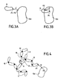
- FIGS. 3A and 3B illustrate the recognition of the interaction distance between an element of articulated object 10 and an object 13d belonging to the environment.
- Figure 3A illustrates in particular the criterion minimum distance between the articulated object 10 and its environment and the points P1 and P2 achieving this minimum distance.
- Figure 3B illustrates the criterion of depth of penetration between the articulated object 10 and its environment, defining the points P1 and P2 achieving this depth of penetration.
- the calculation of the interaction distance makes it possible to extract a point P1, designated “first point” in the remainder of the description, belonging to one of the elements 11 of the articulated object 10 and another point P2, designated “second point” in the rest of the description, belonging to the environment 13.
- the extraction vector V is equal to the coordinates of the first point P1 minus those of the second point P2.
- the second point P2 is the origin of the extraction vector V and the first point P1 is the end of the extraction vector V
- the extraction vector V is equal to the coordinates of the second point P2 minus those of the first point P1.
- the first point P1 is the origin of the extraction vector V and the second point P2 is the end of the extraction vector V .
- this articulated object 10 can be moved away from its environment according to a movement defined according to the single extraction vector V and acting on the overall position, and / or the overall orientation, and / or degrees of freedom of the articulated object 10.
- Figures 4 to 6 illustrate the movements of articulated object according to the minimal distance mode but of course the Principle is the same according to the penetration depth mode.
- Figure 4 illustrates a movement of distance acting on the overall position of the articulated object.
- the translational movement thus contributes to the avoidance of collision by a global displacement of the articulated object 10.
- Figure 5 illustrates a movement of removal acting on the overall orientation of the articulated object.
- the distance of the articulated object 10 from its environment 13 is achieved by determining the rotation to be made around a point, for example the center of gravity G leading to the articulated object 10 to move the point of application of the extraction vector V on the articulated object 10 according to this vector V .
- This rotation is normalized by the value of the pitch of displacement in orientation ⁇ o .
- this rotation movement acting on the orientation overall articulated object 10 can be determined according to the steps below.
- a first vector V 1 g is defined between the center of gravity G of the articulated object 10 and the origin of the extraction vector V .
- the origin of the extraction vector V is the second point P2, but would be the first point P1 in a penetration depth mode.
- a second global vector V 2 g is defined between the center of gravity G of the articulated object 10 and the end P1 of the extraction vector V .
- an angle of rotation ⁇ g designated “global angle of rotation” in the following description, causing the first global vector to coincide V 1 g on the second global vector V 2 g .
- This global rotation angle ⁇ g is decomposed into one or more elementary angles ⁇ gi of global rotation along the axis or axes defining the overall orientation of the articulated object.
- the elementary angles ⁇ gi of global rotation can be calculated by means of one or more scalar products between the global vector product and the axis or axes of the global orientation.
- the hinged object 10 is rotated at one or more angles ⁇ proportional to said elementary angle ⁇ gi of said overall rotation.
- Figure 6 illustrates a joint rotation movement acting at the degrees of freedom of the articulated object.
- the distance of the articulated object 10 from its environment 13 is made in a joint rotational movement acting at each of the joints 12 belonging to a chain of joints which precede the element 11 of the articulated object to which belongs the first point P1 defined above (see Figures 2A and 2B).
- the articulated object is a virtual dummy 10a and if the interaction distance between the manikin 10a and the environment 13 is made by a first point P1 on the forearm, then the chain of joints corresponds to the elbow, shoulder and collarbone.
- the rotational articular motion is calculated to act on all the joints 12 of the arm which precede the forearm.
- the first point P1 belongs to the arm, then the chain of articulation would involve only the shoulder joints and the clavicle. If the first point P1 belongs to the hand then all the 12 joints of the arm would be considered, that is to say that the chain joint would include the wrist, elbow, shoulder and collarbone.
- the hinge chain depends on the element 11 of the articulated object 10 which comprises the first point P1.
- Figure 6 shows the movement articular rotation acting at a given articulation 12a forming part of a chain of joints 12a, 12b, and 12c.
- this articular rotation movement acting at level of a given joint 12a can be determined according to steps below.
- a first vector V 1 l is defined between the articulation center of said given articulation 12a and the origin P2 of the extraction vector V .
- a second local vector V 2 l is defined between the articulation center of said given articulation 12a and the end P1 of the extraction vector V .
- This local rotation angle ⁇ l is decomposed into one or more elementary angles ⁇ li of articular rotation along the axis or axes U i defining the degree or degrees of freedom corresponding to said given articulation 12a of the articulated object 10.
- the given articulation 12a comprises two axes U 1 and U 2 .
- the elementary angles ⁇ li of joint rotation can be calculated by means of one or more scalar products between the local vector product and the axis (s). U i of degree of freedom of the given joint 12a.
- the articulated element at said given hinge is rotated at one or more angles ⁇ i proportional to said elementary angle ⁇ li or articulation.
- the present invention makes it possible to reduce considerably the number of calculations of minimum distance or depth of penetration, which are very demanding in computing time, compared to prior art gradient calculations and without affecting the accuracy of collision avoidance between the articulated object and the environment.
- Figure 7A is a flowchart illustrating the steps main models modeling the movement of the articulated object by avoiding collisions between the latter and the environment.
- Step S0 is an initialization of the flowchart where different parameters are defined. For example, a timing counter of pulses or calculation steps of the modeling is initialized.
- the elementary motions or no displacement in position ⁇ p , in ⁇ o orientation, and in articulation ⁇ a can also be defined in step S0.
- step S1 a calculation of an elementary movement of the object articulated 10 is realized.
- Step S2 is a test to determine whether or not there is a collision between the articulated object 10 and the environment 13.
- the collision criterion depends on the value of the interaction distance.
- the mode based on the minimum distance may consider that a collision has occurred, if this minimum distance is less than or equal to a minimum threshold distance that can be equal to zero to allow the movement of articulated object 10 without collision with its environment 13.
- a collision may be considered to have occurred, if depth is greater than or equal to a threshold penetration depth.
- a threshold penetration depth it is possible, on the one hand, to allow the displacement of articulated object 10 without collision with its environment 13 or on the other hand, allow the displacement of the articulated object 10 with a limited and controlled collision with its environment 13. The latter case allows to model a certain plasticity when the articulated object 10 is in contact with an object of the environment 13.
- step S3 we display for example on the screen 7 of the computer 1, the displacement of the articulated object 10 calculated in step S1 before return to this same step S1 to calculate an elementary displacement next.
- step S3 the extraction steps of the first and second point, of defining the vector of extraction and removal of the articulated object 10 of the environment 13 are not executed.
- step S4 the elementary displacement calculated in step S1.
- step S5 the motion defined in function of the unique extraction vector and acting on the overall position, and / or the overall orientation, and / or degrees of freedom of the articulated object to move the articulated object 10 away from its environment 13, before loop in step S1.
- Figure 7B is a variant of Figure 7A that is valid only in the calculation mode using the penetration depth.
- step S2 when there is a collision in step S2, we go straight ahead in step S5 of the distance of the articulated object 10 from its environment 13, without the cancellation of the last elementary move, allowing thus a slight penetration between the articulated object 10 and its environment 13.
- the displacement of the virtual articulated object 10 in a virtual environment 13 can be implemented by means of a system "Multi-agent” or any other known system.
- Figure 8 illustrates very schematically, a architecture of a multi-agent system 50 that can be used to model the displacement of an articulated object 10.
- This multi-agent system 50 is composed of a set of active elements or agents 20, 21, 22, 23, 30, 31, 32, and 33 acting on the passive objects (elements 11 and joints 12) composing the articulated object 10 according to its environment.
- the data or variables defining the articulated object 10 and its environment are shared data 15 across which the different agents interact with.
- the architecture of the multi-agent system can be organized in several levels or levels, in a pyramidal fashion, so that the agents basic contribute to the actions of those who are on a higher level.
- the multi-agent system 50 has a first level 51 and a second level 52.
- the first level 51 illustrates the overall action or contribution on articulated object 10 and includes the contribution of a first agent global 20 and the contribution of a second global agent acting on articulated object 10 through shared data 15.
- the first global agent 20 acts on the position and orientation of the articulated object 10 and the second global agent 30 acts on the internal degrees of freedom of articulation 12 of the articulated object 10.
- the second level 52 illustrates different contributions, emanating from the different types of agents that generate the contributions first and second global agents 20 and 30 by interacting through shared data 15.
- the displacement of the articulated object 10 can be set by means of an attracting agent acting on the global position, and / or the overall orientation, and / or the plurality of degrees of freedom of the object Speak clearly.
- the distance of the articulated object from its environment can be implemented by means of an agent of slip acting on the overall position, and / or the overall orientation, and / or the plurality of degrees of freedom of the articulated object.
- the second level 52 of the multi-agent system 50 can comprise a repulsive sliding agent 21 acting on the position and / or overall orientation of articulated object 10, an attractant overall 22 acting on the position and / or overall orientation of the object articulated 10, a kinematic sliding agent 31 acting on the degrees of internal freedom of articulation 12 of articulated object 10, and an agent of kinematic attraction 32 acting on internal degrees of freedom articulation 12 of the articulated object 10.
- articulated object 10 can be moved in real time by an operator by means of an operator agent acting on the position and / or the orientation and / or the plurality of degrees of the articulated object.
- the second level 52 of the multi-agent system 50 can also include a global operator agent 23 acting on the position and / or overall orientation of the articulated object 10, and an operator agent internal 33 acting on the internal degrees of freedom of articulation 12 of articulated object 10.
Landscapes
- Engineering & Computer Science (AREA)
- Physics & Mathematics (AREA)
- General Physics & Mathematics (AREA)
- Theoretical Computer Science (AREA)
- Architecture (AREA)
- Computer Graphics (AREA)
- Computer Hardware Design (AREA)
- General Engineering & Computer Science (AREA)
- Software Systems (AREA)
- Manipulator (AREA)
- Processing Or Creating Images (AREA)
- Management, Administration, Business Operations System, And Electronic Commerce (AREA)
Applications Claiming Priority (2)
| Application Number | Priority Date | Filing Date | Title |
|---|---|---|---|
| FR0312641 | 2003-10-29 | ||
| FR0312641A FR2861858B1 (fr) | 2003-10-29 | 2003-10-29 | Deplacement d'un objet articule virtuel dans un environnement virtuel en evitant les collisions entre l'objet articule et l'environnement |
Publications (2)
| Publication Number | Publication Date |
|---|---|
| EP1528511A1 true EP1528511A1 (de) | 2005-05-04 |
| EP1528511B1 EP1528511B1 (de) | 2011-01-26 |
Family
ID=34400874
Family Applications (1)
| Application Number | Title | Priority Date | Filing Date |
|---|---|---|---|
| EP04292230A Expired - Lifetime EP1528511B1 (de) | 2003-10-29 | 2004-09-17 | Verschiebung eines virtuellen Gliederobjekts in einer virtuellen Umgebung unter Vermeidung von Kollisionen zwischen dem Gliederobjekt und der Umgebung |
Country Status (10)
| Country | Link |
|---|---|
| US (1) | US7457733B2 (de) |
| EP (1) | EP1528511B1 (de) |
| JP (1) | JP4942924B2 (de) |
| CN (1) | CN100419796C (de) |
| CA (1) | CA2483083C (de) |
| DE (1) | DE602004031185D1 (de) |
| ES (1) | ES2359239T3 (de) |
| FR (1) | FR2861858B1 (de) |
| RU (1) | RU2308764C2 (de) |
| UA (1) | UA85820C2 (de) |
Families Citing this family (21)
| Publication number | Priority date | Publication date | Assignee | Title |
|---|---|---|---|---|
| US8467904B2 (en) * | 2005-12-22 | 2013-06-18 | Honda Motor Co., Ltd. | Reconstruction, retargetting, tracking, and estimation of pose of articulated systems |
| US8924021B2 (en) * | 2006-04-27 | 2014-12-30 | Honda Motor Co., Ltd. | Control of robots from human motion descriptors |
| JP4986543B2 (ja) * | 2006-08-31 | 2012-07-25 | キヤノン株式会社 | 情報処理方法、情報処理装置 |
| WO2009006727A1 (en) * | 2007-07-12 | 2009-01-15 | Xtranormal Technologie Inc. | Modeling the motion of an articulated object |
| US8170287B2 (en) * | 2007-10-26 | 2012-05-01 | Honda Motor Co., Ltd. | Real-time self collision and obstacle avoidance |
| US8396595B2 (en) * | 2007-11-01 | 2013-03-12 | Honda Motor Co., Ltd. | Real-time self collision and obstacle avoidance using weighting matrix |
| WO2009086088A1 (en) * | 2007-12-21 | 2009-07-09 | Honda Motor Co., Ltd. | Controlled human pose estimation from depth image streams |
| US9165199B2 (en) * | 2007-12-21 | 2015-10-20 | Honda Motor Co., Ltd. | Controlled human pose estimation from depth image streams |
| WO2010099035A1 (en) | 2009-02-25 | 2010-09-02 | Honda Motor Co., Ltd. | Body feature detection and human pose estimation using inner distance shape contexts |
| CN101866386B (zh) * | 2010-06-25 | 2012-04-18 | 杭州维肖软件科技有限公司 | 一种基于能量平衡的柔性体碰撞处理方法 |
| US20120117514A1 (en) * | 2010-11-04 | 2012-05-10 | Microsoft Corporation | Three-Dimensional User Interaction |
| KR20130133778A (ko) | 2010-11-26 | 2013-12-09 | 톰슨 라이센싱 | 트레이싱 정보에 기초한 충돌 회피 방식을 사용하여 캐릭터들을 애니메이팅하기 위한 방법 |
| US9002099B2 (en) * | 2011-09-11 | 2015-04-07 | Apple Inc. | Learning-based estimation of hand and finger pose |
| CN113220116A (zh) | 2015-10-20 | 2021-08-06 | 奇跃公司 | 改变可穿戴设备用户输入模式的系统和方法及可穿戴系统 |
| DE102016102868B4 (de) * | 2016-02-18 | 2024-12-05 | Adrian Drewes | System zur Darstellung von Objekten in einem virtuellen dreidimensionalen Bildraum |
| KR102438052B1 (ko) | 2016-03-31 | 2022-08-29 | 매직 립, 인코포레이티드 | 포즈들 및 멀티-dof 제어기들을 사용하는 3d 가상 객체들과 상호작용들 |
| IL303843B2 (en) | 2016-08-11 | 2024-06-01 | Magic Leap Inc | Automatic placement of a virtual object in a three-dimensional space |
| KR20180108739A (ko) * | 2016-08-30 | 2018-10-04 | 베이징 시아오미 모바일 소프트웨어 컴퍼니 리미티드 | Vr 제어 방법, 장치, 전자 기기, 프로그램 및 저장매체 |
| KR102857458B1 (ko) | 2017-04-19 | 2025-09-09 | 매직 립, 인코포레이티드 | 웨어러블 시스템을 위한 멀티모달 임무 실행 및 텍스트 편집 |
| WO2021224936A1 (en) * | 2020-05-07 | 2021-11-11 | Mimyk Medical Simulations Private Limited | Method and system for real-time simulation of elastic body |
| CN114602177B (zh) * | 2022-03-28 | 2025-08-26 | 百果园技术(新加坡)有限公司 | 虚拟角色的动作控制方法、装置、设备和存储介质 |
Family Cites Families (17)
| Publication number | Priority date | Publication date | Assignee | Title |
|---|---|---|---|---|
| JPS61127007A (ja) * | 1984-11-26 | 1986-06-14 | Hitachi Ltd | ロボツトとワ−クの干渉チエツク方式 |
| US5625577A (en) * | 1990-12-25 | 1997-04-29 | Shukyohojin, Kongo Zen Sohonzan Shorinji | Computer-implemented motion analysis method using dynamics |
| JP3053491B2 (ja) * | 1992-03-10 | 2000-06-19 | 三菱電機株式会社 | 数値制御方法 |
| JP3273443B2 (ja) * | 1992-05-22 | 2002-04-08 | 本田技研工業株式会社 | ロボットのリンクなどの軌道生成方法及び装置 |
| US5548694A (en) * | 1995-01-31 | 1996-08-20 | Mitsubishi Electric Information Technology Center America, Inc. | Collision avoidance system for voxel-based object representation |
| JP3464307B2 (ja) * | 1995-03-24 | 2003-11-10 | シチズン時計株式会社 | Nc旋盤における干渉チェック方法 |
| DE29623747U1 (de) * | 1996-06-25 | 1999-07-08 | Siemens AG, 80333 München | Medizinische Anlage |
| RU2107328C1 (ru) * | 1996-08-14 | 1998-03-20 | Нурахмед Нурисламович Латыпов | Способ отслеживания и отображения положения и ориентации пользователя в пространстве и система для осуществления способа |
| RU2106695C1 (ru) * | 1996-08-14 | 1998-03-10 | Нурахмед Нурисламович Латыпов | Способ представления виртуального пространства пользователю и система для осуществления способа |
| US7472047B2 (en) * | 1997-05-12 | 2008-12-30 | Immersion Corporation | System and method for constraining a graphical hand from penetrating simulated graphical objects |
| US6067096A (en) * | 1998-03-04 | 2000-05-23 | Nagle; John | Method and system for generating realistic collisions in graphical simulations |
| JPH11353493A (ja) * | 1998-06-08 | 1999-12-24 | Hitachi Ltd | 階層管理による物体の映像制御装置及び方法 |
| US6853964B1 (en) * | 2000-06-30 | 2005-02-08 | Alyn Rockwood | System for encoding and manipulating models of objects |
| US6519860B1 (en) * | 2000-10-19 | 2003-02-18 | Sandia Corporation | Position feedback control system |
| US6856319B2 (en) * | 2002-06-13 | 2005-02-15 | Microsoft Corporation | Interpolation using radial basis functions with application to inverse kinematics |
| WO2004028753A2 (en) * | 2002-09-26 | 2004-04-08 | Barrett Technology, Inc. | Intelligent, self-contained robotic hand |
| JP2006507585A (ja) * | 2002-11-15 | 2006-03-02 | ワーナー・ブロス・エンターテイメント・インコーポレーテッド | デジタルモデリング用のリバースレンダリング法 |
-
2003
- 2003-10-29 FR FR0312641A patent/FR2861858B1/fr not_active Expired - Lifetime
-
2004
- 2004-09-17 ES ES04292230T patent/ES2359239T3/es not_active Expired - Lifetime
- 2004-09-17 EP EP04292230A patent/EP1528511B1/de not_active Expired - Lifetime
- 2004-09-17 DE DE602004031185T patent/DE602004031185D1/de not_active Expired - Lifetime
- 2004-10-21 US US10/969,073 patent/US7457733B2/en active Active
- 2004-10-22 CA CA2483083A patent/CA2483083C/fr not_active Expired - Lifetime
- 2004-10-25 RU RU2004131050/09A patent/RU2308764C2/ru active
- 2004-10-25 JP JP2004309120A patent/JP4942924B2/ja not_active Expired - Lifetime
- 2004-10-28 UA UA20041008811A patent/UA85820C2/uk unknown
- 2004-10-29 CN CNB2004100898891A patent/CN100419796C/zh not_active Expired - Lifetime
Non-Patent Citations (6)
| Title |
|---|
| ANDERSON ET AL.: "Robotics and automation", 1994, IEEE INTERNATIONAL CONFERENCE, article "Using virtual objects to aid underground storage tank teleoperation" |
| ANDERSON R J ET AL: "Using virtual objects to aid underground storage tank teleoperation", ROBOTICS AND AUTOMATION, 1994. PROCEEDINGS., 1994 IEEE INTERNATIONAL CONFERENCE ON SAN DIEGO, CA, USA 8-13 MAY 1994, LOS ALAMITOS, CA, USA,IEEE COMPUT. SOC, 8 May 1994 (1994-05-08), pages 1421 - 1426, XP010097707, ISBN: 0-8186-5330-2 * |
| BON B ET AL: "On-line collision avoidance for the Ranger telerobotic flight experiment", ROBOTICS AND AUTOMATION, 1996. PROCEEDINGS., 1996 IEEE INTERNATIONAL CONFERENCE ON MINNEAPOLIS, MN, USA 22-28 APRIL 1996, NEW YORK, NY, USA,IEEE, US, 22 April 1996 (1996-04-22), pages 2041 - 2048, XP010163040, ISBN: 0-7803-2988-0 * |
| BON ET AL.: "Robotics and automation", 1996, IEEE INTERNATIONAL CONFERENCE, article "On-line collision avoidance for the Ranger telerobotic flight experiment" |
| DAMAY; LE ROY: "Réalité virtuelle, maquette numérique du produit, outils de distribution et partage de la conception", JOURNÉES PRIMÉCA, LA PLAGNE 7, 9 April 1999 (1999-04-09) |
| MAILLE B ET AL: "Multi-agent approach and emergence of a virtual human behaviour in a vr environment", IEEE 2002 INTERNATIONAL CONFERENCE ON SYSTEMS, MAN AND CYBERNETICS. (SMC'02). YASMINE HAMMAMET, TUNESIA, OCT. 6 - 9, 2002, IEEE INTERNATIONAL CONFERENCE ON SYSTEMS, MAN, AND CYBERNETICS, NEW YORK, NY: IEEE, US, vol. 7 OF 7, 6 October 2002 (2002-10-06), pages 119 - 124, XP010625598, ISBN: 0-7803-7437-1 * |
Also Published As
| Publication number | Publication date |
|---|---|
| US20050096889A1 (en) | 2005-05-05 |
| RU2308764C2 (ru) | 2007-10-20 |
| FR2861858B1 (fr) | 2014-09-05 |
| US7457733B2 (en) | 2008-11-25 |
| FR2861858A1 (fr) | 2005-05-06 |
| CN1612168A (zh) | 2005-05-04 |
| CA2483083A1 (fr) | 2005-04-29 |
| RU2004131050A (ru) | 2006-04-10 |
| UA85820C2 (uk) | 2009-03-10 |
| JP4942924B2 (ja) | 2012-05-30 |
| CN100419796C (zh) | 2008-09-17 |
| ES2359239T3 (es) | 2011-05-19 |
| DE602004031185D1 (de) | 2011-03-10 |
| CA2483083C (fr) | 2013-12-24 |
| JP2005182759A (ja) | 2005-07-07 |
| EP1528511B1 (de) | 2011-01-26 |
Similar Documents
| Publication | Publication Date | Title |
|---|---|---|
| CA2483083C (fr) | Deplacement d'un objet articule virtuel dans un environnement virtuel en evitant les collisions entre l'objet articule et l'environnement | |
| EP1537960B1 (de) | Bewegung eines virtuellen mit Gelenken ausgestatteten Objektes in einer virtuellen Umgebung mit Selbtkollisionsvermeidung zwischen den Gelenken des Objektes | |
| CA2464800C (fr) | Optimisation de l'ergonomie lors du deplacement d'un mannequin virtuel | |
| CA2674317C (fr) | Procede et systeme permettant la prehension automatisee de piece(s) | |
| EP3942529B1 (de) | Vorhersage der haltung von dreidimensionalem gelenkigem objekt und zielobjekt | |
| EP2956276B1 (de) | Verfahren zur verbesserten erkennung der kollision eines roboters mit seiner umgebung, system und computerprogrammprodukt zur durchführung dieses verfahrens | |
| US20160364786A1 (en) | Automated in store shopping system | |
| JP2018073393A (ja) | 深度マップからの現実の物体の3d再構築 | |
| US11875094B2 (en) | Minimization function for friction solving | |
| US20230304806A1 (en) | Graph-based vehicle route optimization with vehicle capacity clustering | |
| EP3612356A1 (de) | Bestimmung von steuerrichtlinien für roboter mit geräuschtoleranter strukturierter exploration | |
| CN106886165A (zh) | 一种基于模拟器的机械手抓取和操纵方法 | |
| WO2019173556A1 (en) | Adaptive sampling for structured light scanning | |
| EP2081740A1 (de) | Verfahren und vorrichtung zur erfassung einer kollision zwischen zwei numerisch simulierten objekten | |
| FR3070084A1 (fr) | Procede de controle automatique non destructif de pieces mecaniques | |
| WO2010029268A1 (fr) | Procede et dispositif de realisation d'un modele par elements finis | |
| EP3928281A1 (de) | Verfahren zur registrierung von tiefenbildern | |
| Baumgartl et al. | A fast, GPU-based geometrical placement planner for unknown sensor-modelled objects and placement areas | |
| Tan et al. | Opencollbench-benchmarking of collision detection & proximity queries as a web-service | |
| US11845190B1 (en) | Injecting noise into robot simulation | |
| EP3302897A1 (de) | System und verfahren zum testen eines roboter- oder maschinenelements | |
| Nirel et al. | Fast penetration volume for rigid bodies | |
| US20230418433A1 (en) | Pixel-based automated testing of a navigable simulated environment | |
| US20250292514A1 (en) | Self-validating augmented reality inspection of a component | |
| FR3083335A1 (fr) | Procede de generation d'un hologramme numerique, dispositif, systeme de restitution holographique et programme d'ordinateur associes |
Legal Events
| Date | Code | Title | Description |
|---|---|---|---|
| PUAI | Public reference made under article 153(3) epc to a published international application that has entered the european phase |
Free format text: ORIGINAL CODE: 0009012 |
|
| 17P | Request for examination filed |
Effective date: 20040924 |
|
| AK | Designated contracting states |
Kind code of ref document: A1 Designated state(s): AT BE BG CH CY CZ DE DK EE ES FI FR GB GR HU IE IT LI LU MC NL PL PT RO SE SI SK TR |
|
| AX | Request for extension of the european patent |
Extension state: AL HR LT LV MK |
|
| RAP1 | Party data changed (applicant data changed or rights of an application transferred) |
Owner name: SNECMA |
|
| AKX | Designation fees paid |
Designated state(s): DE ES FR GB IT SE |
|
| 17Q | First examination report despatched |
Effective date: 20070724 |
|
| GRAP | Despatch of communication of intention to grant a patent |
Free format text: ORIGINAL CODE: EPIDOSNIGR1 |
|
| GRAS | Grant fee paid |
Free format text: ORIGINAL CODE: EPIDOSNIGR3 |
|
| GRAA | (expected) grant |
Free format text: ORIGINAL CODE: 0009210 |
|
| AK | Designated contracting states |
Kind code of ref document: B1 Designated state(s): DE ES FR GB IT SE |
|
| REG | Reference to a national code |
Ref country code: GB Ref legal event code: FG4D Free format text: NOT ENGLISH |
|
| REF | Corresponds to: |
Ref document number: 602004031185 Country of ref document: DE Date of ref document: 20110310 Kind code of ref document: P |
|
| REG | Reference to a national code |
Ref country code: DE Ref legal event code: R096 Ref document number: 602004031185 Country of ref document: DE Effective date: 20110310 |
|
| REG | Reference to a national code |
Ref country code: SE Ref legal event code: TRGR |
|
| REG | Reference to a national code |
Ref country code: ES Ref legal event code: FG2A Ref document number: 2359239 Country of ref document: ES Kind code of ref document: T3 Effective date: 20110519 |
|
| PLBE | No opposition filed within time limit |
Free format text: ORIGINAL CODE: 0009261 |
|
| STAA | Information on the status of an ep patent application or granted ep patent |
Free format text: STATUS: NO OPPOSITION FILED WITHIN TIME LIMIT |
|
| 26N | No opposition filed |
Effective date: 20111027 |
|
| REG | Reference to a national code |
Ref country code: DE Ref legal event code: R097 Ref document number: 602004031185 Country of ref document: DE Effective date: 20111027 |
|
| PGFP | Annual fee paid to national office [announced via postgrant information from national office to epo] |
Ref country code: ES Payment date: 20120910 Year of fee payment: 9 |
|
| REG | Reference to a national code |
Ref country code: ES Ref legal event code: FD2A Effective date: 20141007 |
|
| PG25 | Lapsed in a contracting state [announced via postgrant information from national office to epo] |
Ref country code: ES Free format text: LAPSE BECAUSE OF NON-PAYMENT OF DUE FEES Effective date: 20130918 |
|
| REG | Reference to a national code |
Ref country code: FR Ref legal event code: PLFP Year of fee payment: 13 |
|
| REG | Reference to a national code |
Ref country code: FR Ref legal event code: PLFP Year of fee payment: 14 |
|
| REG | Reference to a national code |
Ref country code: FR Ref legal event code: CD Owner name: SAFRAN AIRCRAFT ENGINES, FR Effective date: 20170717 |
|
| REG | Reference to a national code |
Ref country code: FR Ref legal event code: PLFP Year of fee payment: 15 |
|
| PGFP | Annual fee paid to national office [announced via postgrant information from national office to epo] |
Ref country code: IT Payment date: 20230822 Year of fee payment: 20 Ref country code: GB Payment date: 20230823 Year of fee payment: 20 |
|
| PGFP | Annual fee paid to national office [announced via postgrant information from national office to epo] |
Ref country code: SE Payment date: 20230822 Year of fee payment: 20 Ref country code: FR Payment date: 20230822 Year of fee payment: 20 Ref country code: DE Payment date: 20230822 Year of fee payment: 20 |
|
| REG | Reference to a national code |
Ref country code: DE Ref legal event code: R071 Ref document number: 602004031185 Country of ref document: DE |
|
| REG | Reference to a national code |
Ref country code: GB Ref legal event code: PE20 Expiry date: 20240916 |
|
| PG25 | Lapsed in a contracting state [announced via postgrant information from national office to epo] |
Ref country code: GB Free format text: LAPSE BECAUSE OF EXPIRATION OF PROTECTION Effective date: 20240916 |
|
| REG | Reference to a national code |
Ref country code: SE Ref legal event code: EUG |
|
| PG25 | Lapsed in a contracting state [announced via postgrant information from national office to epo] |
Ref country code: GB Free format text: LAPSE BECAUSE OF EXPIRATION OF PROTECTION Effective date: 20240916 |