EP1528480B1 - Système de bus avec peu de lignes de commande - Google Patents
Système de bus avec peu de lignes de commande Download PDFInfo
- Publication number
- EP1528480B1 EP1528480B1 EP04025603A EP04025603A EP1528480B1 EP 1528480 B1 EP1528480 B1 EP 1528480B1 EP 04025603 A EP04025603 A EP 04025603A EP 04025603 A EP04025603 A EP 04025603A EP 1528480 B1 EP1528480 B1 EP 1528480B1
- Authority
- EP
- European Patent Office
- Prior art keywords
- bus
- data
- eaibc
- iaibc
- control
- Prior art date
- Legal status (The legal status is an assumption and is not a legal conclusion. Google has not performed a legal analysis and makes no representation as to the accuracy of the status listed.)
- Expired - Lifetime
Links
Images



Classifications
-
- G—PHYSICS
- G06—COMPUTING OR CALCULATING; COUNTING
- G06F—ELECTRIC DIGITAL DATA PROCESSING
- G06F13/00—Interconnection of, or transfer of information or other signals between, memories, input/output devices or central processing units
- G06F13/38—Information transfer, e.g. on bus
- G06F13/40—Bus structure
- G06F13/4004—Coupling between buses
- G06F13/4027—Coupling between buses using bus bridges
- G06F13/4045—Coupling between buses using bus bridges where the bus bridge performs an extender function
-
- G—PHYSICS
- G06—COMPUTING OR CALCULATING; COUNTING
- G06F—ELECTRIC DIGITAL DATA PROCESSING
- G06F13/00—Interconnection of, or transfer of information or other signals between, memories, input/output devices or central processing units
- G06F13/38—Information transfer, e.g. on bus
- G06F13/42—Bus transfer protocol, e.g. handshake; Synchronisation
- G06F13/4204—Bus transfer protocol, e.g. handshake; Synchronisation on a parallel bus
- G06F13/4221—Bus transfer protocol, e.g. handshake; Synchronisation on a parallel bus being an input/output bus, e.g. ISA bus, EISA bus, PCI bus, SCSI bus
- G06F13/423—Bus transfer protocol, e.g. handshake; Synchronisation on a parallel bus being an input/output bus, e.g. ISA bus, EISA bus, PCI bus, SCSI bus with synchronous protocol
Definitions
- a data transmission between a processor core APX-KERN a processor device APX to a plurality of different interface devices IF0, IF1, IF2, ... IF15 is to be performed.
- the processor core APX-KERN has a conventional bus R-BUS with data, address and control lines.
- the bus interfaces IAIBC, EAIBC can access the bus on equal terms.
- a read-ready signal IAIBC-RTR of the internal bus controller or bus interface IAIBC, a read-ready signal EAIBC-RTR of the external bus controller EAIBC and a control signal CTR are transmitted via the three control lines.
- the information or data transmitted via the interface bus AIB via the data lines is identified as payload (user data) or control data or control words SW with the control signal CTR.
- the control signal CTR signals whether actual user data is currently being transmitted via the data lines or the data bus DL or such a user data announcing or requesting control word SW are transmitted.
- the bus clock CL is used by the bus controllers IAIBC, EAIBC.
- the different clock edges of the clock CL are used.
- the control command or the control signal CTR can be sent by both bus control devices IAIBC, EAIBC via the corresponding third control line CTRL. In the normal state, the control signal is in the "low” state. If one of the bus control devices IAIBC, EAIBC wants to send a control command CTR, it sets the control signal CTR briefly or longer in the state "high". To avoid a collision, it is also determined that only the Bus controller IAIBC or EAIBC may activate a control command CTR whose read ready signal IAIBC-RTR or EAIBC-RTR is in the "low” state.
- control word SW on the data lines DL and a control command CTR on the control line CTRL.
- control word SW in particular the type of transfer, for. B. to a register, memory, according to DMA (Direct Memory Access), but also the direction, z. B. whether to read or write, and / or the number or address of the addressed external interface device IFO - IF15 be announced.
- DMA Direct Memory Access
- the external interface device IFO In the case of a desired writing of the central memory (DMA-write), ie the external interface device IFO wants to write data in the central memory, the external interface device IFO sends a DMA request to the external bus controller EAIBC. In the case of more than one simultaneous such request, the external bus control device, which has the highest priority of the requirements. The other requests are queued or rejected.
- the external bus control device IAIBC encodes the number or address of the external interface device IF0 and transmits this in a control word SW via the interface bus AIB. The transmission preferably takes place in accordance with the specifications described above.
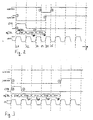
- the external bus controller EAIBC After transmission of the control word SW and of two data packets DP, the external bus controller EAIBC determines that the internal bus controller IAIBC has previously set read ready signal IAIBC-RTR to the state "low" half clock period of the clock CL (FIG. 4), thus not ready to receive is. The external bus controller EAIBC can then interrupt or delay the transmission of further data. Appropriately, the external bus control device goes EAIBC in the state "high” (5) to signal the internal bus controller IAIBC readiness to receive. Thus, with the next rising clock edge of the clock CL, the internal bus control device IAIBC in turn can activate a control signal CTR for one clock period (6) and at the same time set a control word SW on the data lines DL of the interface bus AIB. In the following cycles, the internal bus control device IAIBC sets data packets DP onto the data lines DL. The control word SW and the data packets DP are then received by the external bus control device EAIBC, evaluated and supplied to the corresponding external interface devices
- the internal bus control device IAIBC sets its ready-to-read signal IAIBC-RTR back to the "high" state and is thus ready to receive again (FIG. 8th). With the next rising clock edge, the external bus control device EAIBC can thus again switch to the transmission state (9) - (10), as has been described in accordance with the initial transmission of the first control word and the first data packets.
- the internal bus controller IAIBC sends this data via the interface bus AIB to the external bus controller EAIBC.
- four data packets DP are transmitted, wherein the first 16 data bits of the 32-bit data are first transmitted in a data packet based on "high" state and then in a second data packet based on the low state and then transmitted according to the second 16-bit data (5).
- the external bus controller EAIBC has completely received the 32-bit data, with the first data bit being latched, if necessary, it sends it to the requesting external interface IFO. With the buffering of the received data, the external interface device IF0 clears its request lines and the transmission is terminated.
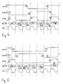
- the external bus control device EAIBC Based on read readiness of the two bus control devices IAIBC, EAIBC, the external bus control device EAIBC switches from one of the external interface devices to the non-read-ready state (1) after the arrival of a DMA read request on the next rising clock edge. In addition, the external submits Bus controller EAIBC the control signal on the control line CTR for one clock period in the state "high" (2). In addition, a corresponding request is generated by the external bus control device EAIBC and transmitted as control word SW via the data lines DL to the interface bus AIB.
- the internal bus controller IAIBC receives this control word SW and switches in the ideal case after appropriate forwarding to the processor core APX-KERN, already half a clock period later with the next falling clock edge of the clock CL in the non-read-ready state (3).
- the external bus control device EAIBC then switches back into the state of readiness for reception, preferably already with the next rising clock edge of the clock CL, and signals this by raising the read ready signal EAIBC-RTR (4).
- the internal bus control device IAIBC can now apply the data received in the meantime via the regular bus R-BUS from the processor core APX-KERN to the next clock cycles of the clock CL on the data lines DL of the interface bus AIB.
- the external bus controller waiting for data packets receives these data packets DL from the interface bus AIB and forwards them to the requesting external interface device IFO (5).
- the external bus control device EAIBC keeps its read ready signal EAIBC-RTR in this state (8), at least for one clock cycle of the clock CL in the low state until the memory is free again or, as in the illustrated embodiment, a new DMA request by the external Interface device IFO or another external interface device IF1 - IF15 arrives at her. Then, in turn, a control command CTR is set to the control line CTRL (9) and a control word SW is applied to the data lines DL of the interface bus AIB (10).
- the starting point is readiness of both bus controllers IAIBC, EAIBC.
- the external bus controller EAIBC After receiving the data request from the external interface device IF0, the external bus controller EAIBC changes its read-ready signal EAIBC-RTR to the non-standby state (1), simultaneously transmits a control signal CTR via the control line (2) and sends a command or control word SW via the data lines DL to the internal bus control device IAIBC. This is done, as in the previous embodiments, together with the rising edge of the clock CL.
- the internal bus control device remains ready to receive in the meantime to be able to receive further data or requests via the interface bus AIB. Blocking of the interface bus AIB is thus reduced to the time actually required for the transmission of control words SW and data packets DP.
- the internal bus control device IAIBC sends the data as data packets DP over the data lines DL, again using one or two 16-bit clocks in the next clock cycles according to the exemplary format. Data packets are transmitted.
- the external bus controller now awaits the requested data on the data lines DL. However, it receives a higher-priority control word SW * from the internal bus control device IAIBC via the data lines DL (5). According to the selected data format then follow data packets (6) via the data lines DL of the interface bus AIB, which belong directly to the higher priority control word SW *.
- Fig. 8 is an illustration of a write operation of the processor APX to a selected one of the external module registers ext IF 0 - ext IF 15 from a read enable signal state IAIBC-RTR, EAIBC-RTR, a step-down control signal CTR, and a continuous bus clock CL of the interface bus AIB out.
- the internal bus controller IAIBC sets its read ready signal after receiving a write request from the processor APX IAIBC-RTR in the state "low", namely on the next falling edge of the clock CL (1).
- the internal bus control device IAIBC After receiving a corresponding read request from the processor core APX-KERN, sets the read ready signal EAIBC-RTR to the state "low" together with the next falling edge of the clock CL of the interface bus AIB (1). On the next rising edge of the clock CL, a control signal CTR is set on the control signal line and the generated control word SW is applied to the data lines DL of the interface bus AIB (2). Soon with the next rising edge, the internal bus control device IAIBC returns to reading readiness (3) in order to be able to receive the requested data.
Landscapes
- Engineering & Computer Science (AREA)
- Theoretical Computer Science (AREA)
- General Engineering & Computer Science (AREA)
- Physics & Mathematics (AREA)
- General Physics & Mathematics (AREA)
- Computer Hardware Design (AREA)
- Bus Control (AREA)
Claims (15)
- Système de bus comportant :- un bus (AIB) permettant l'échange de données (DP) entre deux interfaces de bus (IAIBC, EAIBC),- un premier dispositif de commande de bus (IAIBC) et un deuxième dispositif de commande de bus (EAIBC) pour commander l'échange de données, le premier dispositif de commande de bus (IAIBC) étant alloué à la première interface de bus et le deuxième dispositif de commande de bus (EAIBC) étant alloué à la deuxième interface de bus,- une première et une deuxième lignes de signalisation (I-RTR ou E-RTR) pour signaler les états respectifs du premier ou du deuxième dispositif de commande de bus (IAIBC, EAIBC),- une troisième ligne de signalisation en tant que ligne de commande (CTRL) pour signaler un échange de données,- une ligne de transmission de données ou un bus de données (DL) pour transmettre des données (DM) entre les deux interfaces de bus et- une ligne d'horloge pour synchroniser le système de bus au moyen d'une horloge (CL),dans lequel- les dispositifs de commande de bus (IAIBC, EAIBC) sont des dispositifs de commande de bus émetteurs pour produire un mot de commande (SW), qui se rapporte à des données (DP) à transmettre ensuite, et pour transmettre le mot de commande (SW) par l'intermédiaire de la ligne de transmission de données ou le bus de données (DL), et- les dispositifs de commande de données (IAIBC, EAIBC) sont des dispositifs de commande de bus récepteurs (EAIBC ou IAIBC) pour recevoir le mot de commande (SW) et pour retransmettre à des dispositifs correspondants branchés (IFO, IF1, ... IF15 ou APX-KERN) des données reçues ensuite conformément aux informations de commande contenues dans le mot de commande (SW),caractérisé en ce que
les différents dispositifs de commande de bus (IAIBC, EAIBC) prévus pour éviter les collisions sont uniquement configurés pour des états nettement différents de l'horloge (CL) permettant l'accès au système de bus bidirectionnel. - Système de bus selon la revendication 1,
dans lequel les dispositifs de commande de bus (IAIBC, EAIBC) sont toujours configurés pour transmettre un signal de commande (CTR) sur la ligne de commande (CTRL) lorsque un mot de commande (SW), est transmis par l'intermédiaire de la ligne de transmission de données ou le bus de données (DL). - Système de bus selon la revendication 1 ou 2,
dans lequel le premier et le deuxième dispositifs de commande de bus (IAIBC, EAIBC) sont configurés pour coder des données d'adresse, en particulier des données d'adresse d'un bus classique (R-BUS) et pour les transmettre en tant que mot de commande (SW), ou pour les recevoir en tant mot de commande (SW) et les émettre en tant que données d'adresse décodées, en particulier en tant que données d'adresse décodées sur un bus classique (R-BUS). - Système de bus selon l'une quelconque des revendications précédentes,
dans lequel les dispositifs de commande de bus (IAIBC, EAIBC) sont configurés pour coder des informations de commande, en particulier des demandes d'écriture et de lecture et les transmettre dans le mot de commande (SW) par l'intermédiaire du bus d'interface (AIB) et pour les décoder côté récepteur et pour les mettre, en tant qu'instruction de commande, sur des dispositifs externes, en particulier sur un bus usuel (R-BUS) jusqu'à ce que des données (DP) soient ensuite transmises par l'intermédiaire de la ligne de transmission de données ou du bus de données (DL). - Système de bus selon l'une quelconque des revendications précédentes,
dans lequel les dispositifs de commande de bus (IAIBC, EAIBC) sont configurés pour réécrire des informations de commande reçues préalablement après la réception d'un tel mot de commande (SW). - Système de bus selon l'une quelconque des revendications précédentes,
dans lequel le premier et le deuxième dispositifs de commande de bus (IAIBC, EAIBC) sont configurés pour comparer la priorité d'une demande reçue ayant la priorité d'une transmission instantanée par l'intermédiaire du bus d'interface dans une unité de comparaison (V) et, en fonction du résultat de la comparaison, pour procéder à une interruption de la transmission de données en cours afin de transmettre ensuite des données (DP) ayant une priorité plus haute. - Système de bus selon l'une quelconque des revendications précédentes,
dans lequel la ligne de commande de signalisation (CTR) est configurée pour l'accès bidirectionnel par les dispositifs de commande de bus (IAIBC, EAIBC). - Système de bus selon l'une quelconque des revendications précédentes,
dans lequel la première et la deuxième lignes de signalisation (I-RTR, E-RTR) sont configurées de façon unidirectionnelle opposées et sont allouées au premier ou au deuxième dispositif de commande de bus (IAIBC, ou EAIBC). - Système de bus selon l'une quelconque des revendications précédentes,
dans lequel la première et la deuxième lignes de signalisation (I-RTR, E-RTR) sont configurées pour signaler l'état de disponibilité de réception, ou l'état de non-disponibilité de réception et/ou un envoi en cours du dispositif de commande de bus alloué (IAIBC ou EAIBC). - Système de bus selon l'une quelconque des revendications 1 à 9,
dans lequel le premier et le deuxième dispositifs de commande de bus (IAIBC, EAIBC) sont configurés pour accéder à la ligne de commande (CTRL) au moment de l'état d'horloge alloué de l'horloge (CL). - Système de bus selon l'une quelconque des revendications précédentes,
dans lequel les dispositifs de commande de bus (IAIBC, EAIBC) présentent chacun une unité de comparaison (V) pour déterminer et comparer la priorité de mots de commande (SW) reçus successivement ou d'informations de commande à traiter, l'unité de comparaison (V) autorisant ou n'autorisant pas une interruption de l'échange de données du moment en fonction du résultat de la comparaison des priorités. - Système de bus selon l'une quelconque des revendications précédentes comportant un détecteur (D) prévu pour déterminer un encombrement de données sur des lignes de transmission de données (R-BUS) allant plus loin, le détecteur (D) ralentissant ou interrompant une transmission de données à effectuer par l'intermédiaire du bus d'interface (AIB) en cas d'encombrement de données.
- Système de bus selon l'une quelconque des revendications précédentes,
dans lequel d'autres liaisons de bus (R-BUS) sont raccordées au premier et/ou au deuxième dispositif de commande de bus (IAIBC, EAIBC). - Système de bus selon l'une quelconque des revendications précédentes,
dans lequel le premier ou le deuxième dispositif de commande de bus (IAIBC) est branché sur un noyau de processeur (APX-KERN), en particulier par l'intermédiaire d'un bus usuel (R-BUS) sur le noyau de processeur, et l'autre, le deuxième ou le premier dispositif de commande de bus (EAIBC) est branché sur au moins deux dispositifs d'interface de bus externe (IFO - IF15), en particulier par l'intermédiaire d'un bus usuel (R-BUS) sur les dispositifs d'interface externes. - Système de bus selon la revendication 14,
dans lequel le taux de transmission de données par l'intermédiaire du bus, en particulier du bus d'interface (AIB), est plus faible que le taux de transmission de données par l'intermédiaire du bus usuel (R-BUS).
Applications Claiming Priority (2)
| Application Number | Priority Date | Filing Date | Title |
|---|---|---|---|
| DE10350388 | 2003-10-28 | ||
| DE10350388A DE10350388A1 (de) | 2003-10-28 | 2003-10-28 | Bussystem mit wenigen Steuerleitungen |
Publications (2)
| Publication Number | Publication Date |
|---|---|
| EP1528480A1 EP1528480A1 (fr) | 2005-05-04 |
| EP1528480B1 true EP1528480B1 (fr) | 2007-01-17 |
Family
ID=34399579
Family Applications (1)
| Application Number | Title | Priority Date | Filing Date |
|---|---|---|---|
| EP04025603A Expired - Lifetime EP1528480B1 (fr) | 2003-10-28 | 2004-10-28 | Système de bus avec peu de lignes de commande |
Country Status (3)
| Country | Link |
|---|---|
| US (1) | US7634602B2 (fr) |
| EP (1) | EP1528480B1 (fr) |
| DE (2) | DE10350388A1 (fr) |
Families Citing this family (6)
| Publication number | Priority date | Publication date | Assignee | Title |
|---|---|---|---|---|
| US8856633B2 (en) * | 2007-10-03 | 2014-10-07 | Qualcomm Incorporated | Millimeter-wave communications for peripheral devices |
| JP2009260541A (ja) * | 2008-04-15 | 2009-11-05 | Sony Corp | 送信装置および方法、受信装置および方法、プログラム、並びに、送受信システムおよび方法 |
| KR101736225B1 (ko) * | 2011-12-22 | 2017-05-16 | 인텔 코포레이션 | 커맨드/어드레스 레지스터 디바이스 내에 저장된 데이터에의 액세스 |
| US9517737B2 (en) * | 2013-07-01 | 2016-12-13 | Continental Automotive Systems, Inc. | Relay control between power distribution center and body control module |
| DE102017208835A1 (de) * | 2017-05-24 | 2018-11-29 | Wago Verwaltungsgesellschaft Mbh | Verarbeitung von Prozessdaten |
| US11502812B1 (en) * | 2021-07-14 | 2022-11-15 | Skyworks Solutions, Inc. | Data protocol over clock line |
Family Cites Families (14)
| Publication number | Priority date | Publication date | Assignee | Title |
|---|---|---|---|---|
| US4935894A (en) * | 1987-08-31 | 1990-06-19 | Motorola, Inc. | Multi-processor, multi-bus system with bus interface comprising FIFO register stocks for receiving and transmitting data and control information |
| DD266436B3 (de) | 1987-12-11 | 1993-02-04 | Jenoptik Jena Gmbh | Systembuserweiterung zur kopplung multimasterfaehiger mehrrechnersysteme |
| US5315706A (en) * | 1992-05-27 | 1994-05-24 | National Instruments Corporation | High speed IEEE 488 bus interface system and method |
| US5548790A (en) * | 1993-02-10 | 1996-08-20 | Capital Equipment Corporation | High speed IEEE 488 bus data transfer system |
| US5513377A (en) * | 1994-06-17 | 1996-04-30 | International Business Machines Corporation | Input-output element has self timed interface using a received clock signal to individually phase aligned bits received from a parallel bus |
| US5649129A (en) * | 1995-06-07 | 1997-07-15 | National Instruments Corporation | GPIB system including controller and analyzer |
| US5815690A (en) * | 1995-06-07 | 1998-09-29 | National Instruments Corporation | Deglitch method and apparatus to assure valid data sampling |
| US5812881A (en) | 1997-04-10 | 1998-09-22 | International Business Machines Corporation | Handshake minimizing serial to parallel bus interface in a data processing system |
| DE19733748C2 (de) | 1997-08-04 | 1999-07-15 | Bosch Gmbh Robert | Datenübertragungsvorrichtung |
| US6345330B2 (en) | 1998-05-01 | 2002-02-05 | Acqis Technology, Inc. | Communication channel and interface devices for bridging computer interface buses |
| US6233641B1 (en) | 1998-06-08 | 2001-05-15 | International Business Machines Corporation | Apparatus and method of PCI routing in a bridge configuration |
| US6070214A (en) | 1998-08-06 | 2000-05-30 | Mobility Electronics, Inc. | Serially linked bus bridge for expanding access over a first bus to a second bus |
| US6418494B1 (en) | 1998-10-30 | 2002-07-09 | Cybex Computer Products Corporation | Split computer architecture to separate user and processor while retaining original user interface |
| US6920632B2 (en) * | 2002-08-23 | 2005-07-19 | Xyron Corporation | Dynamic multilevel task management method and apparatus |
-
2003
- 2003-10-28 DE DE10350388A patent/DE10350388A1/de not_active Ceased
-
2004
- 2004-10-27 US US10/975,031 patent/US7634602B2/en not_active Expired - Fee Related
- 2004-10-28 DE DE502004002664T patent/DE502004002664D1/de not_active Expired - Lifetime
- 2004-10-28 EP EP04025603A patent/EP1528480B1/fr not_active Expired - Lifetime
Also Published As
| Publication number | Publication date |
|---|---|
| DE10350388A1 (de) | 2005-06-02 |
| US7634602B2 (en) | 2009-12-15 |
| US20050256988A1 (en) | 2005-11-17 |
| EP1528480A1 (fr) | 2005-05-04 |
| DE502004002664D1 (de) | 2007-03-08 |
Similar Documents
| Publication | Publication Date | Title |
|---|---|---|
| DE69936060T2 (de) | Verfahren und Vorrichtung für eine verbesserte Schnittstelle zwischen Computerkomponenten | |
| EP2030116B1 (fr) | Module de communication | |
| EP0772832B1 (fr) | Arbitrage en cas de couplage de bus retardateur | |
| DE19900345B4 (de) | Schnittstellenmodul für einen Universellen Seriellen Bus (USB) zur Verbindung mit einem USB über eine Programmierschnittstelle für eine USB-Funktion und Vorrichtung zum Anschluß an einen universellen seriellen Bus | |
| DE69130106T2 (de) | Arbitrierung von paketvermittelten Bussen, einschliesslich Bussen von Multiprozessoren mit gemeinsam genutztem Speicher | |
| DE3909948C2 (fr) | ||
| DE69423056T2 (de) | Arbitrierungslogik für Mehrfachbus-Rechnersystem | |
| EP2030118B1 (fr) | Passerelle à processeurs multiples | |
| DE60309391T2 (de) | Datenübertragungssteuerungssystem, Programm und Datenübertragungssteuerungsverfahren | |
| EP0929041A2 (fr) | Méthode et dispositif d'opération d'un système de bus | |
| DE3882991T2 (de) | Anordnung und methode zur erzielung von unterbrechungen mit einem "pended bus". | |
| DE19900325A1 (de) | Vorrichtung und Verfahren zum Senden und Empfangen von Daten in eine und aus einer universellen seriellen Buseinrichtung | |
| WO1996003695A1 (fr) | Reduction de donnees pour coupleurs de bus | |
| DE4142756A1 (de) | Datenweg-einrichtung zur kopplung zweier busse | |
| DE19900369A9 (de) | Vorrichtung und Verfahren zur Ausführung einer Steuerübertragung auf einem Universal Serial Bus | |
| DE10314175A1 (de) | Bussystem sowie Informationsverarbeitungssystem, das ein Bussystem einschliesst | |
| DE69124043T2 (de) | Arbeitsplatzrechner mit Schnittstellenmitteln zur Datenübertragung zwischen zwei Bussen | |
| DE69601060T2 (de) | Integrierbare DDC-Schnittstelle für einen Mikroprozessor | |
| EP1528480B1 (fr) | Système de bus avec peu de lignes de commande | |
| DE102005048581B4 (de) | Teilnehmerschnittstelle zwischen einem FlexRay-Kommunikationsbaustein und einem FlexRay-Teilnehmer und Verfahren zur Übertragung von Botschaften über eine solche Schnittstelle | |
| DE19580195C2 (de) | Verfahren und Einrichtung zur Signalübertragung über eine gemeinsame Leitung | |
| DE10057794B4 (de) | Verfahren für Datentransaktionen zwischen Steuerchipsätzen | |
| DE69125676T2 (de) | Arbeitsplatzrechner mit Direktspeicherzugriffssteuerung | |
| DE69320732T2 (de) | Verfahren zur Gerätadressierung und zur Datensignalübertragung auf einem Bus | |
| DE3247083A1 (de) | Mehrprozessorsystem |
Legal Events
| Date | Code | Title | Description |
|---|---|---|---|
| PUAI | Public reference made under article 153(3) epc to a published international application that has entered the european phase |
Free format text: ORIGINAL CODE: 0009012 |
|
| AK | Designated contracting states |
Kind code of ref document: A1 Designated state(s): AT BE BG CH CY CZ DE DK EE ES FI FR GB GR HU IE IT LI LU MC NL PL PT RO SE SI SK TR |
|
| AX | Request for extension of the european patent |
Extension state: AL HR LT LV MK |
|
| 17P | Request for examination filed |
Effective date: 20050614 |
|
| AKX | Designation fees paid |
Designated state(s): DE FR GB IT NL |
|
| GRAP | Despatch of communication of intention to grant a patent |
Free format text: ORIGINAL CODE: EPIDOSNIGR1 |
|
| GRAS | Grant fee paid |
Free format text: ORIGINAL CODE: EPIDOSNIGR3 |
|
| GRAA | (expected) grant |
Free format text: ORIGINAL CODE: 0009210 |
|
| AK | Designated contracting states |
Kind code of ref document: B1 Designated state(s): DE FR GB IT NL |
|
| REG | Reference to a national code |
Ref country code: GB Ref legal event code: FG4D Free format text: NOT ENGLISH |
|
| GBT | Gb: translation of ep patent filed (gb section 77(6)(a)/1977) |
Effective date: 20070117 |
|
| REF | Corresponds to: |
Ref document number: 502004002664 Country of ref document: DE Date of ref document: 20070308 Kind code of ref document: P |
|
| ET | Fr: translation filed | ||
| PLBE | No opposition filed within time limit |
Free format text: ORIGINAL CODE: 0009261 |
|
| STAA | Information on the status of an ep patent application or granted ep patent |
Free format text: STATUS: NO OPPOSITION FILED WITHIN TIME LIMIT |
|
| 26N | No opposition filed |
Effective date: 20071018 |
|
| PGFP | Annual fee paid to national office [announced via postgrant information from national office to epo] |
Ref country code: DE Payment date: 20091026 Year of fee payment: 6 |
|
| PGFP | Annual fee paid to national office [announced via postgrant information from national office to epo] |
Ref country code: NL Payment date: 20091016 Year of fee payment: 6 |
|
| PGFP | Annual fee paid to national office [announced via postgrant information from national office to epo] |
Ref country code: FR Payment date: 20091110 Year of fee payment: 6 Ref country code: GB Payment date: 20091022 Year of fee payment: 6 Ref country code: IT Payment date: 20091024 Year of fee payment: 6 |
|
| REG | Reference to a national code |
Ref country code: NL Ref legal event code: V1 Effective date: 20110501 |
|
| GBPC | Gb: european patent ceased through non-payment of renewal fee |
Effective date: 20101028 |
|
| PG25 | Lapsed in a contracting state [announced via postgrant information from national office to epo] |
Ref country code: FR Free format text: LAPSE BECAUSE OF NON-PAYMENT OF DUE FEES Effective date: 20101102 |
|
| REG | Reference to a national code |
Ref country code: FR Ref legal event code: ST Effective date: 20110630 |
|
| PG25 | Lapsed in a contracting state [announced via postgrant information from national office to epo] |
Ref country code: GB Free format text: LAPSE BECAUSE OF NON-PAYMENT OF DUE FEES Effective date: 20101028 Ref country code: NL Free format text: LAPSE BECAUSE OF NON-PAYMENT OF DUE FEES Effective date: 20110501 |
|
| REG | Reference to a national code |
Ref country code: DE Ref legal event code: R119 Ref document number: 502004002664 Country of ref document: DE Effective date: 20110502 |
|
| PG25 | Lapsed in a contracting state [announced via postgrant information from national office to epo] |
Ref country code: IT Free format text: LAPSE BECAUSE OF NON-PAYMENT OF DUE FEES Effective date: 20101028 |
|
| PG25 | Lapsed in a contracting state [announced via postgrant information from national office to epo] |
Ref country code: DE Free format text: LAPSE BECAUSE OF NON-PAYMENT OF DUE FEES Effective date: 20110502 |