EP1528399A2 - Sensor mit Zweidrahtversorgung und Stromausgang, sowie zugehörige integrierte Schaltung - Google Patents
Sensor mit Zweidrahtversorgung und Stromausgang, sowie zugehörige integrierte Schaltung Download PDFInfo
- Publication number
- EP1528399A2 EP1528399A2 EP04025674A EP04025674A EP1528399A2 EP 1528399 A2 EP1528399 A2 EP 1528399A2 EP 04025674 A EP04025674 A EP 04025674A EP 04025674 A EP04025674 A EP 04025674A EP 1528399 A2 EP1528399 A2 EP 1528399A2
- Authority
- EP
- European Patent Office
- Prior art keywords
- detecting element
- signal processing
- power supply
- processing circuit
- wire type
- Prior art date
- Legal status (The legal status is an assumption and is not a legal conclusion. Google has not performed a legal analysis and makes no representation as to the accuracy of the status listed.)
- Withdrawn
Links
Images


Classifications
-
- G—PHYSICS
- G01—MEASURING; TESTING
- G01D—MEASURING NOT SPECIALLY ADAPTED FOR A SPECIFIC VARIABLE; ARRANGEMENTS FOR MEASURING TWO OR MORE VARIABLES NOT COVERED IN A SINGLE OTHER SUBCLASS; TARIFF METERING APPARATUS; MEASURING OR TESTING NOT OTHERWISE PROVIDED FOR
- G01D5/00—Mechanical means for transferring the output of a sensing member; Means for converting the output of a sensing member to another variable where the form or nature of the sensing member does not constrain the means for converting; Transducers not specially adapted for a specific variable
- G01D5/12—Mechanical means for transferring the output of a sensing member; Means for converting the output of a sensing member to another variable where the form or nature of the sensing member does not constrain the means for converting; Transducers not specially adapted for a specific variable using electric or magnetic means
- G01D5/14—Mechanical means for transferring the output of a sensing member; Means for converting the output of a sensing member to another variable where the form or nature of the sensing member does not constrain the means for converting; Transducers not specially adapted for a specific variable using electric or magnetic means influencing the magnitude of a current or voltage
- G01D5/142—Mechanical means for transferring the output of a sensing member; Means for converting the output of a sensing member to another variable where the form or nature of the sensing member does not constrain the means for converting; Transducers not specially adapted for a specific variable using electric or magnetic means influencing the magnitude of a current or voltage using Hall-effect devices
- G01D5/145—Mechanical means for transferring the output of a sensing member; Means for converting the output of a sensing member to another variable where the form or nature of the sensing member does not constrain the means for converting; Transducers not specially adapted for a specific variable using electric or magnetic means influencing the magnitude of a current or voltage using Hall-effect devices influenced by the relative movement between the Hall device and magnetic fields
-
- G—PHYSICS
- G01—MEASURING; TESTING
- G01P—MEASURING LINEAR OR ANGULAR SPEED, ACCELERATION, DECELERATION, OR SHOCK; INDICATING PRESENCE, ABSENCE, OR DIRECTION, OF MOVEMENT
- G01P1/00—Details of instruments
- G01P1/02—Housings
- G01P1/026—Housings for speed measuring devices, e.g. pulse generator
-
- G—PHYSICS
- G01—MEASURING; TESTING
- G01P—MEASURING LINEAR OR ANGULAR SPEED, ACCELERATION, DECELERATION, OR SHOCK; INDICATING PRESENCE, ABSENCE, OR DIRECTION, OF MOVEMENT
- G01P3/00—Measuring linear or angular speed; Measuring differences of linear or angular speeds
- G01P3/42—Devices characterised by the use of electric or magnetic means
- G01P3/44—Devices characterised by the use of electric or magnetic means for measuring angular speed
- G01P3/48—Devices characterised by the use of electric or magnetic means for measuring angular speed by measuring frequency of generated current or voltage
- G01P3/481—Devices characterised by the use of electric or magnetic means for measuring angular speed by measuring frequency of generated current or voltage of pulse signals
- G01P3/489—Digital circuits therefor
Definitions
- This invention generally relates to a two-wire type current output sensor and IC therefor.
- a known two-wire type current output sensor is disclosed in JP10(1998)-332725A.
- the disclosed sensor includes two external connection terminals.
- One of the external connection terminals is defined as a power supply terminal to which the power supply current flows from the outside
- the other one of the external connection terminals is defined as a GND terminal (output terminal) from which the power supply current flows to the outside.
- the current flowing from the GND terminal i.e. current level
- a detection signal of a detecting element to be an output signal. Therefore, only two wires connected to the power supply terminal and the GND terminal are required for a supply line to the disclosed two-wire type current output sensor.
- the aforementioned two-wire type current output sensor is mainly used as a rotation sensor for ABS, AT, and the like in the vehicle.
- the direction of flow of the current is decided at respective (i.e. two) external connection terminals. That is, as shown in Fig. 7, for example, two external connection terminals T1 and T2 are provided on a sensor body 10 on which a rotation detecting IC (current output IC) storing a magnetic detecting element S (Hall element) and a signal processing circuit 100 is mounted. Then, one terminal T1 is determined as the power supply terminal and connected to a power supply side terminal VIN of the rotation detecting IC while the other terminal T2 is determined as the GND terminal and connected to the current output side terminal OUT of the rotation detecting IC.
- Rs is a detection resistance provided at the outside.
- the aforementioned two-wire type current output sensor includes two magnetic detecting elements for outputting respective rotation detection signals having different phase relations from each other in accordance with a rotation direction of a rotating member (detected member) so that the rotation direction of the rotating member in addition to the rotation speed can be recognized. Then, the signal processing circuit changes the protocol of the current output signal in accordance with the change of the rotation direction of the rotating member (for example, the current wave is changed in accordance with the rotation direction).
- the detecting element face i.e. face of the sensor that can detect the detected member via the detecting element
- two external connection terminals T1 and T2 are determined as the power supply terminal and the GND terminal respectively.
- the power supply terminal T1 may be determined as the power supply terminal while the power supply terminal T2 may be determined as the GND terminal, or the power supply terminal T1 may be determined as the GND terminal while the power supply terminal T2 may be determined as the power supply terminal regardless of the mounting position of the signal processing circuit 100 (precisely, the rotation detecting IC) on the sensor, the designing flexibility of the harness for supplying power to the sensor and the like may be increased.
- a left-wheel rotation sensor and a right-wheel rotation sensor for ABS for example, having a function of detecting a rotation direction include sensor bodies 10A and 10B respectively being symmetrical each other.
- respective harnesses for power supply with respective connectors CNs having the equal terminal arrangement to each other are used for the left-wheel rotation sensor and the right wheel rotation sensor.
- the sensors should be configured such that respective rotation base directions for the right-wheel rotation sensor and the left-wheel rotation sensor are different from each other.
- a rotation detecting IC 1 for the left wheel and a rotation detecting IC 2 for the right wheel should be mounted on the sensor bodies 10A and 10B respectively such that the ICs 1 and 2 are symmetrical each other to thereby bring each detecting face (front side) faces a rotor L
- a protocol 1 is output in the rotation direction in which a magnetic pole of the rotor L is detected in order by detecting elements 1 and 2 while a protocol 2 is output in the reverse rotation direction.
- the protocol 1 is output in the rotation direction in which the magnetic pole of the rotor L is detected in order by the detecting elements 2 and 1 while the protocol 2 is output in the reverse rotation direction. Accordingly, two types of signal processing circuits or signal processing ICs are required so that the rotation base directions for the left-wheel sensor and the right-wheel sensor are different from each other, which may cause a cost increase.
- a two-wire type current output sensor including two external connection terminals to one of which a power supply flows from an outside and from the other one of which the power supply flows to the outside, a detecting element provided so as to face a detected member and capable of outputting a detection signal, and a signal processing circuit for changing a current supplied to a power supply side of the signal processing circuit based on the detection signal of the detecting element and outputting the changed current
- the two-wire type current output sensor further includes a connection switching circuit for switching a connection between the two external connection terminals and the signal processing circuit such that one of the external connection terminals at a higher voltage is connected to the power supply side of the signal processing circuit while the other one of the external connection terminals at a lower voltage is connected to an output side of the signal processing circuit.
- the power supply current is supplied from the outside to the power supply side of the signal processing circuit via one of the external connection terminals at a higher voltage (i.e. power supply terminal) while the output current in accordance with the detection signal of the detecting element is output from the output side of the signal processing circuit to the outside via the other one of the external connection terminals at a lower voltage (i.e. GND terminal).
- two external connection terminals are each switchable between the power supply terminal and the GND terminal.
- the electrode arrangement (i.e. power supply and GND) of the connecter and the like connected to two external connection terminals is in a reverse connection state by failure, a fail-sensor function is activated due to a specific system that triggers a normal operation, thereby assuring a proper sensor function.
- a two-wire type current output circuit and IC therefor including two external connection terminals to one of which a power supply flows from an outside and from the other one of which the power supply flows to the outside, a detecting element provided so as to face a detected member and capable of outputting a detection signal, and a signal processing circuit for changing a current supplied to a power supply side of the signal processing circuit based on the detection signal of the detecting element and outputting the changed current characterized in that the detecting element is stored in an IC package including two detecting faces facing each other.
- the same detecting sensitivity may be obtained by both the detecting faces.
- the mounting restriction may be eased by using the IC package storing the detecting element such as the Hall IC, MR (magnetic resistance), IC and the like with assuring the same detection sensitivity.
- the detecting element such as the Hall IC, MR (magnetic resistance), IC and the like with assuring the same detection sensitivity.
- Fig. 1 is a block diagram showing a basic configuration of a two-wire type current output sensor according to an embodiment of the present invention
- Fig. 2 is a block diagram showing a detailed configuration of the two-wire type current output sensor according to the embodiment of the present invention
- Fig. 3 is a block diagram showing a detailed configuration of the two-wire type current output sensor according to the embodiment of the present invention.
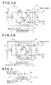
- Fig. 4A is a view showing a using status of the two-wire type current output sensor of Fig. 3;
- Fig. 4B is a view showing a using status of the two-wire type current output sensor of Fig. 3;
- Fig. 5 is a cross-sectional view of a configuration of another two-wire type current output sensor
- Fig. 6 is a view showing a using status of the two-wire type current output sensor of Fig. 5;
- Fig. 7 is a block diagram showing a configuration of a conventional two-wire type current output sensor
- Fig. 8 is a view showing a using status of the conventional two-wire type current output sensor.
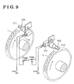
- Fig. 9 is a perspective view showing a state in which the two-wire current output sensor is applied for detecting each rotation of left and right wheels.
- a two-wire type current output sensor includes two external connection terminals Ta and Tb to one of which the power supply current flows from the outside and from the other one of which the power supply current flows to the outside, a detecting element S provided, facing a detected member for outputting a detection signal, and a signal processing circuit 100 for changing the current supplied to a power supply side of the signal processing circuit 100 based on the detection signal of the detecting element S and outputting that changed current.
- the two-wire type current output sensor also includes a connection switching circuit 200 for switching the connection between the two external connection terminals Ta and Tb, and the signal processing circuit 100 so that one of the external connection terminals Ta and Tb at a higher voltage is connected to a power supply side VIN of the signal processing circuit 100 while the other one of the external connection terminals Ta and Tb at a lower voltage is connected to an output side OUT of the signal processing circuit 100.
- a known rotation detecting IC storing the detecting element S such as a Hall element, and the signal processing circuit 100 is mounted on a sensor body 10 equipped with the external connection terminals Ta and Tb at end portions.
- a power supply terminal VIN of the rotation detecting IC corresponds to the power supply side VIN of the signal processing circuit 100 while a current output terminal OUT of the rotation detecting IC corresponds to the output side OUT of the signal processing circuit 100.
- a rotating member such as a rotor (not shown) is defined as the detected member in Fig. 1.
- the connection switching circuit 200 connects the external connection terminal Ta with the power supply terminal VIN of the rotation detecting IC (i.e. the power supply side VIN of the signal processing circuit 100), and also connects the external connection terminal Tb with the current output terminal OUT of the rotation detecting IC (i.e. the output side OUT of the signal processing circuit 100) in case that a voltage Va of the external connection terminal Ta and a voltage Tb of the external connection terminal Tb are compared with each other and then Va>Vb+V1 is obtained.
- the connection switching circuit 200 connects the external connection terminal Ta with the current output terminal OUT of the rotation detecting IC (i.e.
- V1 and V2 are threshold values defined for stably performing the switching operation by the connection switching circuit 200.
- Fig. 2 shows a detailed example of the connection switching circuit 200 in Fig. 1.
- the connection switching circuit 200 is constituted by a simple switching circuit by using a transistor, diode, and the like. Accordingly, in case that an external power supply is connected to the external connection terminal Ta and at the same time a current output circuit on GND side is connected to the external connection terminal Tb, or, inversely, the current output circuit on GND side is connected to the external connection terminal Ta and at the same time the external power supply is connected to the external connection terminal Tb, the signal processing circuit 100 is properly powered within the two-wire type current output sensor. The connection switching is performed with assuring the normal sensor function.
- Fig. 3 shows an example of the two-wire type current output sensor storing the detecting element S, the signal processing circuit 100 and the connection switching circuit 200.
- a different type of IC 3 having two external signal terminals T ⁇ and T ⁇ on a power supply side and an output side relative to the connection switching circuit 200 is mounted on the two-wire type current output sensor. That is, the switching circuit constituted by external parts such as transistor and diode is provided as an internal circuit of the IC3.
- the restriction of mounting arrangement may be greatly eased by employing the IC3 storing the connection switching circuit 200 as in the following explanation referring to Fig. 4.
- the IC3 is then mounted so as to be upside down as shown in Fig. 4B without changing the connection status of the external power supply and GND relative to the two external connection terminals Ta and Tb.
- the two external signal terminals T ⁇ and T ⁇ of the IC3 may be connected with the two external connection terminals Ta and Tb via a shortest route. Since the detecting face is provided on a predetermined side, i.e. only one side, of the detecting element S in the IC 3, when the detecting face is provided on the front side in Fig. 4A, for example, then the IC3 should be arranged such that the detecting face is positioned on a back side in Fig. 4B.
- the detecting element S (precisely, detecting elements S1 and S2 to be mentioned later) is stored in an IC package 11.
- the IC package 11 includes two detecting faces 11a and 11b facing the detecting element S with keeping respective distances k1 and k2.
- the distances k1 and k2 are equal to each other.
- at least the detecting element S is desirably stored and mounted in the IC package having two detecting faces 11a and 11b.
- the detecting element S is not a single element and constituted by two detecting elements S1 and S2 for outputting respective rotation detecting signals having different phase relations from each other in accordance with a rotation direction of the rotation member (rotor L) as the detected member. That is, the detecting element S can be constituted by two or more of the detecting elements outputting the respective rotation detecting signals having different phase relations from each other in accordance with the rotation direction of the rotation member (rotor L).
- the signal processing circuit 100 is constituted so as to change the output current in accordance with the rotation speed signal of the rotation member (rotor L) under the condition that the rotation direction of the rotation member can be identified (see Fig. 6).
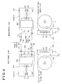
- Fig. 6 shows an example of employing the IC4 for detecting the rotation of right and left wheels for ABS and the like (see Fig. 9).
- the IC4 is mounted on a sensor body 10A for the left wheel such that one detecting face 11a (front side) of the package 11 is arranged, facing the rotor L of the left wheel with keeping a detection gap g therebetween. Then, when the rotor L of the left wheel rotates in the normal direction as shown in Fig. 6, the rotor L is detected in order by the detecting elements S1 and then S2.
- the IC4 is mounted on a sensor body 10B for a right wheel such that the other detecting face 11b (back side) of the package 11 is arranged, facing the rotor L of the right wheel with keeping the same detection gap g therebetween as that for the left-wheel side. Then, when the rotor L of the right wheel rotates in the normal direction, the rotor L is detected in order by the detecting elements S1 and then S2. That is, a base rotation direction is same in the respective rotation sensors for the left and right wheels and thus the IC4 with a single type of protocol may be utilized.
- the detected member is the rotation member (rotor L).
- the detected member is not limited to the rotation member and various kinds of objects may be employed.
- the magnetic detecting element such as the Hall element
- various kinds of detecting elements may be employed for the detecting elements S, S1 and S2.
- the IC 3 further stores the connection switching circuit 200 in addition to the detecting element S and the signal processing circuit 100.
- two external signal terminals T ⁇ and T ⁇ on the power supply side and the output side of the IC 3 relative to the connection switching circuit 200 are connected to the two external connection terminals Ta and Tb of the sensor body 10 respectively.
- the power supply terminal and the GND terminal may be switched therebetween by the connection switching circuit 200 in the IC 3 in accordance with the voltage level of the two external connection terminals of the sensor body 10.
- the IC 3 may be mounted on the sensor body 10 with less restriction when the two external signal terminals T ⁇ and T ⁇ of the IC 3 are connected to the two external connection terminals Ta and Tb of the sensor body 10 respectively.
- the restriction of mounting the IC 3 on the sensor body 10 may be further eased while the two external connection terminals of the sensor body 10 can be switched between the power supply terminal and the GND terminal.
- the IC package 11 storing the detecting element S is mounted on the sensor body 10 such that any one of two detecting faces on the IC package 11, being positioned at equal distances from the detecting element S to each other, faces the detecting element S, the distances between the respective detecting faces and the detected member are equal to each other and thus the same detecting sensitivity may be obtained by the respective detecting faces.
- the mounting restriction may be eased by using the IC package storing the detecting element S such as the Hall IC, MR (magnetic resistance), IC and the like with assuring the same detection sensitivity.
- the detecting element S such as the Hall IC, MR (magnetic resistance), IC and the like with assuring the same detection sensitivity.
- the identical base rotation direction is achieved in each rotation sensor even when a single type of the rotation detecting IC storing two or more of the detecting elements is mounted on each of the symmetrical sensor bodies by turning over the rotation detecting IC, i.e. the front side and the back side thereof.
- Two types of rotation detecting IC with the different base rotation directions from each other are not required accordingly.
- a two-wire type current output sensor including two external connection terminals to one of which a power supply flows from an outside and from the other one of which the power supply flows to the outside, a detecting element capable of outputting a detection signal, and a signal processing circuit for changing a current supplied to a power supply side of the signal processing circuit based on the detection signal and outputting the changed current characterized in that the two-wire type current output sensor further includes a connection switching circuit for switching a connection between the two external connection terminals and the signal processing circuit such that one of the external connection terminals at a higher voltage is connected to the power supply side of the signal processing circuit while the other one of the external connection terminals at a lower voltage is connected to an output side.
Landscapes
- Physics & Mathematics (AREA)
- General Physics & Mathematics (AREA)
- Transmission And Conversion Of Sensor Element Output (AREA)
- Electronic Switches (AREA)
- Arrangements For Transmission Of Measured Signals (AREA)
Applications Claiming Priority (2)
| Application Number | Priority Date | Filing Date | Title |
|---|---|---|---|
| JP2003371827A JP2005134283A (ja) | 2003-10-31 | 2003-10-31 | 2線式の電流出力センサ及び該センサ用ic |
| JP2003371827 | 2003-10-31 |
Publications (2)
| Publication Number | Publication Date |
|---|---|
| EP1528399A2 true EP1528399A2 (de) | 2005-05-04 |
| EP1528399A3 EP1528399A3 (de) | 2005-06-29 |
Family
ID=34420228
Family Applications (1)
| Application Number | Title | Priority Date | Filing Date |
|---|---|---|---|
| EP04025674A Withdrawn EP1528399A3 (de) | 2003-10-31 | 2004-10-28 | Sensor mit Zweidrahtversorgung und Stromausgang, sowie zugehörige integrierte Schaltung |
Country Status (3)
| Country | Link |
|---|---|
| US (1) | US7208941B2 (de) |
| EP (1) | EP1528399A3 (de) |
| JP (1) | JP2005134283A (de) |
Cited By (1)
| Publication number | Priority date | Publication date | Assignee | Title |
|---|---|---|---|---|
| CN110712607A (zh) * | 2019-10-29 | 2020-01-21 | 一汽解放汽车有限公司 | 一种车用加速度和角速度测量系统 |
Families Citing this family (5)
| Publication number | Priority date | Publication date | Assignee | Title |
|---|---|---|---|---|
| WO2007132389A1 (en) * | 2006-05-12 | 2007-11-22 | Nxp B.V. | Current interface with a blocking capacitor attached to an additional pin |
| DE102007026786A1 (de) * | 2006-08-21 | 2008-04-03 | Continental Teves Ag & Co. Ohg | Aktiver Sensor mit Betriebsmodus-Umschaltung |
| US7719411B2 (en) * | 2007-06-12 | 2010-05-18 | Robert Bosch Gmbh | Method and system of transmitting a plurality of movement parameters of a vehicle via a two-wire interface |
| CN105606132B (zh) * | 2016-01-28 | 2017-10-27 | 东南大学 | 一种基于二线制等电势法的阻性传感器阵列读出电路 |
| CN106595721B (zh) * | 2016-12-12 | 2019-01-22 | 南京工程学院 | 改进的二维电阻阵列快速读出电路 |
Family Cites Families (15)
| Publication number | Priority date | Publication date | Assignee | Title |
|---|---|---|---|---|
| DE2113307C3 (de) * | 1971-03-19 | 1980-09-18 | Alfred Teves Gmbh, 6000 Frankfurt | Aufnehmer für eine induktive Geschwindigkeitsmeßeinrichtung |
| CA954644A (en) * | 1972-11-28 | 1974-09-10 | Microsystems International Limited | Polarity guard |
| DE3408657A1 (de) * | 1984-03-09 | 1985-09-12 | Wolfgang 7500 Karlsruhe Sorgatz | Polungsautomatik fuer automatische ladeeinrichtungen fuer aufladbare batterien |
| DE3618500A1 (de) * | 1986-06-02 | 1987-12-03 | Siemens Ag | Schaltungsanordnung zum verpolschutz |
| DE3934504A1 (de) * | 1989-10-16 | 1991-04-25 | Siemens Ag | Verpolungsschutz-schaltungsanordnung |
| ES2110555T3 (es) * | 1992-10-21 | 1998-02-16 | Bosch Gmbh Robert | Dispositivo para la deteccion del movimiento de una parte movil. |
| EP0740776B1 (de) * | 1994-11-22 | 2002-06-12 | Robert Bosch Gmbh | Anordnung zur berührungslosen drehwinkelerfassung eines drehbaren elements |
| IT235863Y1 (it) * | 1995-05-19 | 2000-07-18 | Skf Ind Spa | Dispositivo di rilevamento della velocita' di rotazione con sensorestaccabile. |
| DE19532328A1 (de) * | 1995-09-01 | 1997-03-06 | Teves Gmbh Alfred | Radlagersensor zum Messen von Dreh- oder Winkelbewegungen |
| FR2755192B1 (fr) * | 1996-10-25 | 1998-11-27 | Roulements Soc Nouvelle | Dispositif de retenue d'une tete de montage d'un capteur d'informations sur un support annulaire |
| JP4093381B2 (ja) * | 1997-04-01 | 2008-06-04 | 株式会社デンソー | 回転センサの検出信号処理装置 |
| DE19937155A1 (de) * | 1999-08-06 | 2001-03-15 | Bosch Gmbh Robert | System zur Erzeugung eines Signals zur Überlagerung von Informationen |
| CN2391205Y (zh) * | 1999-08-13 | 2000-08-09 | 杨泰和 | 具电流检测回授功能的自动极交换装置 |
| DE10150760A1 (de) * | 2000-12-06 | 2002-08-14 | Continental Teves Ag & Co Ohg | Anordnung zur Übertragung von Reifendruckinformation |
| DE10391610D2 (de) * | 2002-04-18 | 2005-01-27 | Continental Teves Ag & Co Ohg | Verfahren und Vorrichtung zur Erfassung von Ortsverschiebungen und Drehbewegungen |
-
2003
- 2003-10-31 JP JP2003371827A patent/JP2005134283A/ja active Pending
-
2004
- 2004-10-28 EP EP04025674A patent/EP1528399A3/de not_active Withdrawn
- 2004-11-01 US US10/976,898 patent/US7208941B2/en not_active Expired - Fee Related
Cited By (1)
| Publication number | Priority date | Publication date | Assignee | Title |
|---|---|---|---|---|
| CN110712607A (zh) * | 2019-10-29 | 2020-01-21 | 一汽解放汽车有限公司 | 一种车用加速度和角速度测量系统 |
Also Published As
| Publication number | Publication date |
|---|---|
| EP1528399A3 (de) | 2005-06-29 |
| US7208941B2 (en) | 2007-04-24 |
| US20060091879A1 (en) | 2006-05-04 |
| JP2005134283A (ja) | 2005-05-26 |
Similar Documents
| Publication | Publication Date | Title |
|---|---|---|
| WO2012164915A2 (en) | Detecting device and current sensor | |
| KR20060006042A (ko) | 2개 배선을 통한 전계 효과 센서 상호접속 방법 및 장치 | |
| US20110313696A1 (en) | Battery monitoring system | |
| CN101176002A (zh) | 用于固有安全的车轮转速检测的系统 | |
| CN110603451B (zh) | 电子控制装置 | |
| EP1528399A2 (de) | Sensor mit Zweidrahtversorgung und Stromausgang, sowie zugehörige integrierte Schaltung | |
| JP4066723B2 (ja) | 位置検出センサ | |
| JP2007508529A (ja) | 回転数センサ、特に有用車両で使用される回転数センサを選択的に接続するための電子回路装置 | |
| JP4149440B2 (ja) | アナログセンサのための保護回路 | |
| US6844723B2 (en) | Rotation detecting device | |
| US11128244B2 (en) | Device for detecting rotation direction and method for detecting rotation direction of motor, and motor control device | |
| JPH0694772A (ja) | 異常検出機能を有した2値信号検出回路 | |
| JPH0325275Y2 (de) | ||
| JPH11223639A (ja) | 回転速度検出装置 | |
| JP2002288776A (ja) | 検知装置 | |
| KR102599288B1 (ko) | 차량 제어 장치 | |
| EP4418525A1 (de) | Systeme und verfahren zur motorpositionsmessung | |
| US7235976B2 (en) | Sensor for measuring the position of an actuating element | |
| WO2018025218A1 (en) | Circuital device with reed functionality | |
| US20050068021A1 (en) | Sensor system having a single-wire interface | |
| JP3179417B2 (ja) | 強磁性物体通過センサ | |
| JPH04110774A (ja) | 移動量検出センサーとそれを用いた自動車 | |
| JPH0742575U (ja) | モータの回転検出回路 | |
| JPS59139494A (ja) | 信号源用増幅回路 | |
| JPH01311927A (ja) | 車両用断芯検出装置 |
Legal Events
| Date | Code | Title | Description |
|---|---|---|---|
| PUAI | Public reference made under article 153(3) epc to a published international application that has entered the european phase |
Free format text: ORIGINAL CODE: 0009012 |
|
| AK | Designated contracting states |
Kind code of ref document: A2 Designated state(s): AT BE BG CH CY CZ DE DK EE ES FI FR GB GR HU IE IT LI LU MC NL PL PT RO SE SI SK TR |
|
| AX | Request for extension of the european patent |
Extension state: AL HR LT LV MK |
|
| PUAL | Search report despatched |
Free format text: ORIGINAL CODE: 0009013 |
|
| RIC1 | Information provided on ipc code assigned before grant |
Ipc: 7G 01P 1/02 B Ipc: 7H 02H 11/00 B Ipc: 7G 01P 3/489 A |
|
| AK | Designated contracting states |
Kind code of ref document: A3 Designated state(s): AT BE BG CH CY CZ DE DK EE ES FI FR GB GR HU IE IT LI LU MC NL PL PT RO SE SI SK TR |
|
| AX | Request for extension of the european patent |
Extension state: AL HR LT LV MK |
|
| 17P | Request for examination filed |
Effective date: 20050704 |
|
| AKX | Designation fees paid |
Designated state(s): DE FR GB |
|
| STAA | Information on the status of an ep patent application or granted ep patent |
Free format text: STATUS: THE APPLICATION HAS BEEN WITHDRAWN |
|
| 18W | Application withdrawn |
Effective date: 20100923 |