EP1528348B1 - Heat exchanger - Google Patents
Heat exchanger Download PDFInfo
- Publication number
- EP1528348B1 EP1528348B1 EP04024691.0A EP04024691A EP1528348B1 EP 1528348 B1 EP1528348 B1 EP 1528348B1 EP 04024691 A EP04024691 A EP 04024691A EP 1528348 B1 EP1528348 B1 EP 1528348B1
- Authority
- EP
- European Patent Office
- Prior art keywords
- heat exchanger
- structures
- tubes
- housing
- sheet
- Prior art date
- Legal status (The legal status is an assumption and is not a legal conclusion. Google has not performed a legal analysis and makes no representation as to the accuracy of the status listed.)
- Expired - Lifetime
Links
Images

Classifications
-
- F—MECHANICAL ENGINEERING; LIGHTING; HEATING; WEAPONS; BLASTING
- F28—HEAT EXCHANGE IN GENERAL
- F28F—DETAILS OF HEAT-EXCHANGE AND HEAT-TRANSFER APPARATUS, OF GENERAL APPLICATION
- F28F1/00—Tubular elements; Assemblies of tubular elements
- F28F1/10—Tubular elements and assemblies thereof with means for increasing heat-transfer area, e.g. with fins, with projections, with recesses
- F28F1/12—Tubular elements and assemblies thereof with means for increasing heat-transfer area, e.g. with fins, with projections, with recesses the means being only outside the tubular element
- F28F1/14—Tubular elements and assemblies thereof with means for increasing heat-transfer area, e.g. with fins, with projections, with recesses the means being only outside the tubular element and extending longitudinally
-
- F—MECHANICAL ENGINEERING; LIGHTING; HEATING; WEAPONS; BLASTING
- F28—HEAT EXCHANGE IN GENERAL
- F28D—HEAT-EXCHANGE APPARATUS, NOT PROVIDED FOR IN ANOTHER SUBCLASS, IN WHICH THE HEAT-EXCHANGE MEDIA DO NOT COME INTO DIRECT CONTACT
- F28D7/00—Heat-exchange apparatus having stationary tubular conduit assemblies for both heat-exchange media, the media being in contact with different sides of a conduit wall
- F28D7/16—Heat-exchange apparatus having stationary tubular conduit assemblies for both heat-exchange media, the media being in contact with different sides of a conduit wall the conduits being arranged in parallel spaced relation
- F28D7/163—Heat-exchange apparatus having stationary tubular conduit assemblies for both heat-exchange media, the media being in contact with different sides of a conduit wall the conduits being arranged in parallel spaced relation with conduit assemblies having a particular shape, e.g. square or annular; with assemblies of conduits having different geometrical features; with multiple groups of conduits connected in series or parallel and arranged inside common casing
- F28D7/1653—Heat-exchange apparatus having stationary tubular conduit assemblies for both heat-exchange media, the media being in contact with different sides of a conduit wall the conduits being arranged in parallel spaced relation with conduit assemblies having a particular shape, e.g. square or annular; with assemblies of conduits having different geometrical features; with multiple groups of conduits connected in series or parallel and arranged inside common casing the conduit assemblies having a square or rectangular shape
-
- F—MECHANICAL ENGINEERING; LIGHTING; HEATING; WEAPONS; BLASTING
- F28—HEAT EXCHANGE IN GENERAL
- F28F—DETAILS OF HEAT-EXCHANGE AND HEAT-TRANSFER APPARATUS, OF GENERAL APPLICATION
- F28F1/00—Tubular elements; Assemblies of tubular elements
- F28F1/10—Tubular elements and assemblies thereof with means for increasing heat-transfer area, e.g. with fins, with projections, with recesses
- F28F1/12—Tubular elements and assemblies thereof with means for increasing heat-transfer area, e.g. with fins, with projections, with recesses the means being only outside the tubular element
- F28F1/126—Tubular elements and assemblies thereof with means for increasing heat-transfer area, e.g. with fins, with projections, with recesses the means being only outside the tubular element consisting of zig-zag shaped fins
-
- F—MECHANICAL ENGINEERING; LIGHTING; HEATING; WEAPONS; BLASTING
- F28—HEAT EXCHANGE IN GENERAL
- F28F—DETAILS OF HEAT-EXCHANGE AND HEAT-TRANSFER APPARATUS, OF GENERAL APPLICATION
- F28F9/00—Casings; Header boxes; Auxiliary supports for elements; Auxiliary members within casings
- F28F9/02—Header boxes; End plates
- F28F9/026—Header boxes; End plates with static flow control means, e.g. with means for uniformly distributing heat exchange media into conduits
- F28F9/0265—Header boxes; End plates with static flow control means, e.g. with means for uniformly distributing heat exchange media into conduits by using guiding means or impingement means inside the header box
- F28F9/0268—Header boxes; End plates with static flow control means, e.g. with means for uniformly distributing heat exchange media into conduits by using guiding means or impingement means inside the header box in the form of multiple deflectors for channeling the heat exchange medium
-
- F—MECHANICAL ENGINEERING; LIGHTING; HEATING; WEAPONS; BLASTING
- F28—HEAT EXCHANGE IN GENERAL
- F28D—HEAT-EXCHANGE APPARATUS, NOT PROVIDED FOR IN ANOTHER SUBCLASS, IN WHICH THE HEAT-EXCHANGE MEDIA DO NOT COME INTO DIRECT CONTACT
- F28D21/00—Heat-exchange apparatus not covered by any of the groups F28D1/00 - F28D20/00
- F28D21/0001—Recuperative heat exchangers
- F28D21/0003—Recuperative heat exchangers the heat being recuperated from exhaust gases
-
- F—MECHANICAL ENGINEERING; LIGHTING; HEATING; WEAPONS; BLASTING
- F28—HEAT EXCHANGE IN GENERAL
- F28F—DETAILS OF HEAT-EXCHANGE AND HEAT-TRANSFER APPARATUS, OF GENERAL APPLICATION
- F28F2215/00—Fins
- F28F2215/04—Assemblies of fins having different features, e.g. with different fin densities
Definitions
- the invention relates to a heat exchanger, in particular for a motor vehicle, according to the preamble of claim 1, DE 10060102 discloses such a heat exchanger.
- a heat exchanger is provided with a housing and at least one tube arranged in the housing, wherein structures are provided between the tubes and the housing and / or the tubes: the primary medium flows through the tubes.
- the secondary medium is guided in the interstices between the tubes and / or between the tubes and the housing, in which also the structures are arranged are.
- the structures increase the strength through a stiffening with respect to internal and external pressure stresses of the pipes.
- the coupling between tubes and housing also provides a continuous compensation of the thermal stresses between the primary and secondary sides over the entire length of the radiator, so that the stresses at the ends of the tubes are significantly reduced.
- the structures also serve for fluid conduction and distribution in the heat exchanger.
- the ribbed plates also allow a better heat transfer, so that thermoelectric voltages can be reduced by the improved heat transfer. Due to the increased transfer surface, the tubes are better cooled and boiling can be avoided. Overall, this results in a significant increase in the power density of the heat exchanger over conventional heat exchangers without structures.
- Preferred structures are sheet metal structures in the form of separate tubes, ribbed plates, dimpled plates, or the like. inserted.
- the heat exchanger may in particular be an exhaust gas heat exchanger or charge air cooler, but also another heat exchanger, for example another gas-liquid heat exchanger in which hot gas flows through the heat exchanger (cooler) in tubes for cooling, a liquid-gas heat exchanger, in which cold gas in pipes passes through the heat exchanger (heater) for heating, or be a liquid-liquid heat exchanger.
- the tubes and / or the housing can be correspondingly formed with structures, ie, in particular, the pipe surface may be formed rib-like and / or knob-like.
- the structures preferably have a height of 1 mm to 5 mm, preferably 1 mm to 3 mm, particularly preferably 1.5 mm.
- the pitch L of the structures is preferably 0.1 to 6 times, more preferably 0.5 to 4 times the structural height h.
- the transverse dimension Q is preferably 0.15 to 8 times, more preferably 0.5 to 5 times the structural height h.
- the ratio of channel height between the tubes and channel height in the tube is in the range of structures preferably 0.1 to 1, preferably 0.2 to 0.7.
- the hydraulic diameter between the tubes in the region with structures is preferably 0.5 mm to 10 mm, preferably 1 mm to 5 mm.
- the structures with the housing and / or the pipes are firmly connected, in particular soldered.
- a fixed connection over a large length of the heat exchanger without or with interruptions, for example, for better coolant distribution provided.
- the fixed connection increases the external pressure resistance (overpressure on the secondary side) very efficiently because the structures provide tie rods that prevent the tube from collapsing.
- vibrations of the tubes which are relatively unstable in conventional heat exchangers, are damped by the structures, and a very efficient compensation of the thermoelectric voltages is brought about.
- the fixed connection supports the heat transfer from the tubes to the structures, so that a better cooling of the tubes takes place. By an improved heat transfer can also reduce the number of tubes, so that the production costs can be reduced.
- the tubes are preferably at least partially formed by flat tubes.
- Flat tubes are thermodynamically much more efficient than round tubes, but have a lower pressure resistance, which is why pressure-increasing measures are required for flat tubes, as inventively a support structure on the outside of the tube.
- the flat tubes in particular have an approximately rectangular cross-section with rounded corners.
- one-piece rectangular tubes can be provided. These can have a longitudinal seam, which can be welded, for example laser-welded, friction-welded, induction-welded, or soldered.
- the rectangular tubes can also be constructed of shells that are welded or soldered.
- the tubes may also have any other shape, for example. Oval, and / or have lateral tabs which are soldered or welded.
- the tubes for tolerance compensation between the housing and tubes and the structures arranged therebetween may be slightly convex.
- Turbulizers winglets
- the pipe surface inside and / or outside
- the pipe surface can also be structured to generate turbulence.
- the structures preferably have an inhomogeneous structure at least partially, as a result of which coolant can be supplied to critical areas in a targeted manner, so that overheating or boiling can be avoided. A corresponding increased supply of coolant can also be achieved by the partial omission of structures. These measures can be used to optimize the pressure loss of the heat exchanger and the transverse distribution of the coolant in the heat exchanger.
- the regions with inhomogeneous structures are preferably in the region of the inlet and / or outlet of the fluid. They serve in particular the flow control and to keep the pressure loss as low as possible.
- the housing is preferably formed in two or more parts, in particular as a U-shaped shell with a lid, wherein a water tank can be formed integrated in the lid.
- a water tank can be formed integrated in the lid.
- a one-piece construction for example with a molded-on water tank, possible.
- Structures may also be provided in the tubes themselves, with all the above-mentioned structures that may be provided between the tubes also being able to be integrated into the tubes.
- the structures are preferably formed by rib plates or dimpled sheets, which are connected to the pipe, for example, by welding, soldering or jamming.
- the structures preferably have a height of 1 mm to 5 mm, preferably 1 mm to 3 mm, particularly preferably 1.5 mm.
- the pitch L of the structures is preferably 0.5 to 6 times the structural height h.
- the transverse dimension Q is preferably 0.5 to 8 times the structural height h.
- the hydraulic diameter in the tube in the region with structures is preferably 0.5 mm to 10 mm, preferably 1 mm to 5 mm.
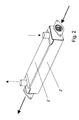
- An exhaust gas heat exchanger 1 has a two-part housing 2 and a plurality of tubes 3 arranged in this housing 2. Ribs 4 are provided as structures between the individual tubes 3 and between the housing 2 and the tubes 3, these ribbed plates 4 being toothed in accordance with the present exemplary embodiment, as in FIG Fig. 3 shown and described in more detail later.
- the tubes 3 are in the present case flat tubes.
- the housing 2 in which the tubes 3 are arranged consists of a U-shaped first housing part 2 'and a housing cover 2 ", which is set from above onto the first housing part 2.
- the housing 2' For the inlet and outlet of the coolant (liquid secondary medium ) are two coolant nozzle 5 in the housing cover 2 "provided, wherein the flow direction of the coolant in DC operation in Fig. 2 is shown by dashed arrows. It is also possible to flow through in countercurrent operation, including the flow direction is reversed. Since the coolant is passed through the housing 2 and around the tubes 3, the fin sheets 4 are arranged on the coolant side.
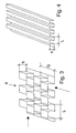
- the straight toothed ribbed plates 4 point in the direction of in Fig. 3 Arrow shown with a solid line a slight passage and in the dashed line arrow on a heavier passage for the coolant.
- the flow can be influenced.
- these can also specifically support the coolant delivery to particularly critical points, including the rib sheets 4 are at least partially formed inhomogeneous.
- a simple variant of a ribbed plate is shown with a rib running in a straight direction, which has a longitudinal pitch L of 2.4 mm and a rib or structural height h of 1.5 mm.
- the ribbed sheet can also be bent from a perforated plate, so that the individual corrugations are permeable due to the perforation.
- a corresponding structure for a charge air cooler is used.
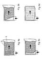
- Fig. 5a-d show various inhomogeneous regions of the rib sheets 4 forming structures. These cause a better distribution of the fluid in the inflow.
- the in Fig. 5a is shown, transverse distribution channels are provided by forming or stamping.
- the rib bleaching 4 were partially cut off.
- Fig. 5d shows a variant with a special formed on the rib sheet 4 manifold structure. A the FIGS. 5a to 5d corresponding inhomogeneous region can also be provided on the outflow side.
Landscapes
- Engineering & Computer Science (AREA)
- Physics & Mathematics (AREA)
- Thermal Sciences (AREA)
- Mechanical Engineering (AREA)
- General Engineering & Computer Science (AREA)
- Geometry (AREA)
- Heat-Exchange Devices With Radiators And Conduit Assemblies (AREA)
- Exhaust-Gas Circulating Devices (AREA)
Description
Die Erfindung betrifft einen Wärmetauscher, insbesondere für ein Kraftfahrzeug, gemäß dem Oberbegriff des Anspruchs 1,
Um die zunehmenden Anforderungen an moderne Motoren bezüglich Emissionsreduzierung und Kraftstoffverbrauch erfüllen zu können, sind umfangreiche Maßnahmen, wie zum Beispiel erhöhte Aufladung, genauere Beeinflussung der Verbrennungsbedingungen, erforderlich. Dies führt auch bei Kraftfahrzeug-Wärmetauschern zu härteren Einsatzbedingungen, nämlich höheren Gas- und Kühlmitteldrücken, erhöhten Temperaturen und größeren Volumendurchsätzen. Gleichzeitig wachsen die Anforderungen an die Leistungsdichte und Lebensdauer. Teilweise sind daher neue Kühlkonzepte erforderlich. So werden bei Ladeluft-Kühlern die herkömmlicher Weise verwendeten Luft/Luft-Kühler zumindest teilweise durch Luft/Flüssigkeits-Kühler ersetzt, um die geforderten Leistungen und Leistungsdichten zu erzielen, die auf Grund der hohen Motoraufladung erforderlich sind. Bei Abgas-Wärmetauschern sind immer höhere Abgasrückführraten erforderlich bei ebenfalls immer härteren Betriebsbedingungen bezüglich Drücken, Temperaturen und Leistungsdichten. Somit treten bei modernen Wärmetauschern immer höhere mechanische Belastungen auf, insbesondere in Hinblick auf Druck und Schwingungen.In order to meet the increasing demands on modern engines with regard to emission reduction and fuel consumption, extensive measures, such as increased charging, more precise influence on the combustion conditions, are required. This also leads to harsher operating conditions in motor vehicle heat exchangers, namely higher gas and coolant pressures, elevated temperatures and higher volume throughputs. At the same time, the demands on power density and service life are growing. Partly, therefore, new cooling concepts are required. Thus, in charge air coolers, the air / air coolers conventionally used are at least partially replaced by air / liquid coolers to achieve the required performances and power densities required due to the high engine boost. With exhaust gas heat exchangers, ever higher exhaust gas recirculation rates are required, with ever-increasing operating conditions with regard to pressures, temperatures and power densities. Thus occur in modern heat exchangers ever higher mechanical loads, especially with regard to pressure and vibration.
Hohe Temperaturunterschiede des zu kühlenden Primärmediums (in der Regel gasförmig) und des kühlenden Sekundärmediums (hier in der Regel flüssig) führen zu unterschiedlichen Bauteilerhitzungen auf der Primär- und Sektundärseite. Bei Abgas-Wärmetauschern kann die Temperaturdifferenz bis zu über 700K, bei Ladeluft-Kühlern bis zu 300K betragen. Dabei kommt es zu in Folge unterschiedlicher thermischer Längenausdehnungen zwischen Primär- und Sekundärseite zu starken Thermospannungen. Bei schnellen Wechseln des Betriebszustands können diese Thermospannungen durch ungleichmäßige Temperaturverteilungen noch verstärkt werden (Thermoschock).High temperature differences of the primary medium to be cooled (usually gaseous) and the cooling secondary medium (here usually liquid) lead to different component heating on the primary and Sektundärseite. For exhaust gas heat exchangers, the temperature difference can be up to more than 700K, for charge air coolers up to 300K. This leads to strong thermal stresses as a result of different thermal expansion between the primary and secondary side. In the case of rapid changes of the operating state, these thermoelectric voltages can be exacerbated by uneven temperature distributions (thermal shock).
Auf Grund höherer Leistungsdichten der Wärmetauscher erhöht sich zudem die Gefahr des Siedens des Kühlmittels, was zu starken Leistungs- und Lebensdauereinbußen führen kann.Due to higher power densities of the heat exchanger also increases the risk of boiling of the coolant, which can lead to strong performance and loss of life.
Schließlich sind die verwendeten Prozesse und Materialien wegen des Auftretens stark korrosiver Medium, z.B. Kondensat aus dem Abgas beim Abgas-Wärmetauscher, stark eingeschränkt, was bei weiter zunehmenden Anforderungen an die Leistungsdichte zu immer größeren Problemen führt, eine dauerfeste technische Lösung zur Verfügung zu stellen, eine ausreichende Innen- und Außendruckfestigkeit der Strömungskanäle, ein Vermeiden des Siedens und ausreichende Festigkeit gegen Schwingungsanregungen und Thermospannungen miteinander zu vereinen.Finally, the processes and materials used are highly corrosive medium due to the occurrence, e.g. Condensate from the exhaust gas in the exhaust gas heat exchanger, severely limited, which leads to ever greater problems with increasing demands on power density, a durable technical solution to provide sufficient internal and external pressure resistance of the flow channels, avoid boiling and sufficient To combine strength against vibration excitations and thermal voltages.
Es ist Aufgabe der Erfindung, einen verbesserten Wärmetauscher zur Verfügung zu stellen.It is an object of the invention to provide an improved heat exchanger.
Diese Aufgabe wird gelöst durch einen Wärmetauscher mit den Merkmalen des Anspruchs 1. Vorteilhafte Ausgestaltungen sind Gegenstand der Unteransprüche.This object is achieved by a heat exchanger with the features of
Erfindungsgemäß ist ein Wärmetauscher vorgesehen, mit einem Gehäuse und mindestens einem in dem Gehäuse angeordneten Rohr, wobei Strukturen zwischen den Rohren und dem Gehäuse und/oder den Rohren vorgesehen sind: Das Primärmedium durchströmt die Rohre. Das Sekundärmedium wird in den Zwischenräumen zwischen den Rohren und/oder zwischen den Rohren und dem Gehäuse geführt, in denen auch die Strukturen angeordnet sind. Die Strukturen erhöhen die Festigkeit durch eine Versteifung bezüglich Innen- und Außendruckbeanspruchungen der Rohre. Durch die Koppelung zwischen Rohren und Gehäuse erfolgt zudem ein kontinuierlicher Ausgleich der Thermospannungen zwischen Primär- und Sekundärseite über die gesamte Kühlerlänge, so dass die Spannungen an den Enden der Rohre deutlich reduziert werden. Die Strukturen dienen zudem der Fluidleitung und - verteilung im Wärmetauscher. Dabei ermöglichen die Rippenbleche ferner einen besseren Wärmeübergang, so dass durch die verbesserte Wärmeübertragung Thermospannungen reduziert werden können. Durch die erhöhte Übertragungsfläche werden die Rohre besser gekühlt und ein Sieden kann vermieden werden. Insgesamt ergibt sich somit eine erhebliche Steigerung der Leistungsdichte des Wärmetauschers gegenüber herkömmlichen Wärmetauschern ohne Strukturen. Bevorzugt werden als Strukturen Blechstrukturen in Form von separaten Rohren, Rippenblechen, Noppenblechen, o.ä. eingeschoben. Der Wärmetauscher kann insbesondere ein Abgas-Wärmetauscher oder Ladeluft-Kühler, jedoch auch ein anderer Wärmetauscher, beispielsweise ein anderer Gas-Flüssigkeits-Wärmetauscher, bei dem heißes Gas in Rohren den Wärmetauscher (Kühler) zur Kühlung durchströmt, ein Flüssigkeits-Gas-Wärmetauscher, bei dem kaltes Gas in Rohren den Wärmetauscher (Heizer) zum Erwärmen durchströmt, oder ein Flüssigkeits-Flüssigkeits-Wärmetauscher sein. Anstelle der Verwendung von Blechstrukuren können auch die Rohre und/oder das Gehäuse entsprechend mit Strukturen ausgebildet sein, d.h. insbesondere kann die Rohroberfläche rippenartig und/oder noppenartige ausgebildet sein. Die Strukturen weisen bevorzugt eine Höhe von 1 mm bis 5 mm, vorzugsweise 1 mm bis 3 mm, insbesondere bevorzugt 1,5 mm auf. Die Teilung L der Strukturen beträgt bevorzugt das 0,1- bis 6fache, besonders bevorzugt das 0,5- bis 4fache der Strukturhöhe h. Die Querteilung Q beträgt bevorzugt das 0,15- bis 8fache, besonders bevorzugt das 0,5- bis 5fache der Strukturhöhe h. Das Verhältnis von Kanalhöhe zwischen den Rohren und Kanalhöhe im Rohr beträgt im Bereich von Strukturen bevorzugt 0,1 bis 1, vorzugsweise 0,2 bis 0,7. Der hydraulische Durchmesser zwischen den Rohren beträgt im Bereich mit Strukturen bevorzugt 0,5 mm bis 10 mm, vorzugsweise 1 mm bis 5 mm.According to the invention, a heat exchanger is provided with a housing and at least one tube arranged in the housing, wherein structures are provided between the tubes and the housing and / or the tubes: the primary medium flows through the tubes. The secondary medium is guided in the interstices between the tubes and / or between the tubes and the housing, in which also the structures are arranged are. The structures increase the strength through a stiffening with respect to internal and external pressure stresses of the pipes. The coupling between tubes and housing also provides a continuous compensation of the thermal stresses between the primary and secondary sides over the entire length of the radiator, so that the stresses at the ends of the tubes are significantly reduced. The structures also serve for fluid conduction and distribution in the heat exchanger. The ribbed plates also allow a better heat transfer, so that thermoelectric voltages can be reduced by the improved heat transfer. Due to the increased transfer surface, the tubes are better cooled and boiling can be avoided. Overall, this results in a significant increase in the power density of the heat exchanger over conventional heat exchangers without structures. Preferred structures are sheet metal structures in the form of separate tubes, ribbed plates, dimpled plates, or the like. inserted. The heat exchanger may in particular be an exhaust gas heat exchanger or charge air cooler, but also another heat exchanger, for example another gas-liquid heat exchanger in which hot gas flows through the heat exchanger (cooler) in tubes for cooling, a liquid-gas heat exchanger, in which cold gas in pipes passes through the heat exchanger (heater) for heating, or be a liquid-liquid heat exchanger. Instead of the use of sheet metal structures, the tubes and / or the housing can be correspondingly formed with structures, ie, in particular, the pipe surface may be formed rib-like and / or knob-like. The structures preferably have a height of 1 mm to 5 mm, preferably 1 mm to 3 mm, particularly preferably 1.5 mm. The pitch L of the structures is preferably 0.1 to 6 times, more preferably 0.5 to 4 times the structural height h. The transverse dimension Q is preferably 0.15 to 8 times, more preferably 0.5 to 5 times the structural height h. The ratio of channel height between the tubes and channel height in the tube is in the range of structures preferably 0.1 to 1, preferably 0.2 to 0.7. The hydraulic diameter between the tubes in the region with structures is preferably 0.5 mm to 10 mm, preferably 1 mm to 5 mm.
Bevorzugt sind die Strukturen mit dem Gehäuse und/oder den Rohren fest verbunden, insbesondere verlötet. Dabei ist insbesondere eine feste Verbindung über einen Großteil Länge des Wärmetauschers ohne oder mit Unterbrechungen, beispielsweise zur besseren Kühlmittelverteilung, vorgesehen. Durch die feste Verbindung wird sehr effizient die Außendruckfestigkeit (Überdruck auf der Sekundärseite) erhöht, da die Strukturen Zuganker bereitstellen, die das Einfallen des Rohres verhindern. Weiterhin werden Schwingungen der bei herkömmlichen Wärmetauschern relativ labilen Rohre durch die Strukturen gedämpft, sowie ein sehr effizienter Ausgleich der Thermospannungen herbeigeführt. Ferner unterstützt die feste Verbindung den Wärmeübergang von den Rohren zu den Strukturen, so dass eine bessere Kühlung der Rohre erfolgt. Durch einen verbesserten Wärmeübergang lässt sich außerdem die Zahl der Rohre reduzieren, so dass die Herstellungskosten gesenkt werden können.Preferably, the structures with the housing and / or the pipes are firmly connected, in particular soldered. In particular, a fixed connection over a large length of the heat exchanger without or with interruptions, for example, for better coolant distribution provided. The fixed connection increases the external pressure resistance (overpressure on the secondary side) very efficiently because the structures provide tie rods that prevent the tube from collapsing. Furthermore, vibrations of the tubes, which are relatively unstable in conventional heat exchangers, are damped by the structures, and a very efficient compensation of the thermoelectric voltages is brought about. Furthermore, the fixed connection supports the heat transfer from the tubes to the structures, so that a better cooling of the tubes takes place. By an improved heat transfer can also reduce the number of tubes, so that the production costs can be reduced.
Die Rohre werden vorzugsweise zumindest teilweise durch Flachrohre gebildet. Dabei sind Flachrohre thermodynamisch wesentlich leistungsfähiger als Rundrohre, haben jedoch eine geringere Druckfestigkeit, weshalb bei Flachrohren druckfestigkeitssteigernde Maßnahmen erforderlich sind, wie erfindungsgemäß eine Stützstruktur auf der Rohraußenseite. Dabei haben die Flachrohre insbesondere einen etwa rechteckförmigen Querschnitt mit gerundeten Ecken. Ferner können einteilige Rechteckrohre vorgesehen sein. Diese können eine Längsnaht aufweisen, die geschweißt, bspw. lasergeschweißt, reibgeschweißt, induktionsgeschweißt, oder verlötet sein kann. Die Rechteckrohre können auch aus Schalen aufgebaut sein, die verschweißt oder verlötet sind. Die Rohre können auch eine beliebige andere Form, bspw. oval, aufweisen und/oder seitliche Laschen aufweisen, die verlötet oder verschweißt werden. Ferner können die Rohre zum Toleranzausgleich zwischen Gehäuse und Rohren sowie den dazwischen angeordneten Strukturen leicht ballig ausgebildet sein. In und/oder an den Rohren können auch Turbulatoren (Winglets) vorgesehen sein. Die Rohroberfläche (innen und/oder außen) kann zur Turbulenzerzeugung auch strukturiert ausgebildet sein.The tubes are preferably at least partially formed by flat tubes. Flat tubes are thermodynamically much more efficient than round tubes, but have a lower pressure resistance, which is why pressure-increasing measures are required for flat tubes, as inventively a support structure on the outside of the tube. The flat tubes in particular have an approximately rectangular cross-section with rounded corners. Furthermore, one-piece rectangular tubes can be provided. These can have a longitudinal seam, which can be welded, for example laser-welded, friction-welded, induction-welded, or soldered. The rectangular tubes can also be constructed of shells that are welded or soldered. The tubes may also have any other shape, for example. Oval, and / or have lateral tabs which are soldered or welded. Furthermore, the tubes for tolerance compensation between the housing and tubes and the structures arranged therebetween may be slightly convex. Turbulizers (winglets) can also be provided in and / or on the pipes. The pipe surface (inside and / or outside) can also be structured to generate turbulence.
Bevorzugt weisen die Strukturen zumindest teilweise einen inhomogenen Aufbau auf, wodurch gezielt Kühlmittel kritischen Bereichen zugeleitet werden kann, so dass ein Überhitzen oder Sieden vermieden werden kann. Eine entsprechende erhöhte Zuleitung von Kühlmittel kann auch durch das teilweise Weglassen von Strukturen erreicht werden. Durch diese Maßnahmen lässt sich der Druckverlust des Wärmetauschers und die Querverteilung des Kühlmittel im Wärmetauscher optimieren. Die Bereiche mit inhomogenen Strukturen liegen vorzugsweise im Bereich des Ein- und/oder Auslaufs des Fluids. Sie dienen insbesondere der Strömungslenkung und um den Druckverlust möglichst gering zu halten.The structures preferably have an inhomogeneous structure at least partially, as a result of which coolant can be supplied to critical areas in a targeted manner, so that overheating or boiling can be avoided. A corresponding increased supply of coolant can also be achieved by the partial omission of structures. These measures can be used to optimize the pressure loss of the heat exchanger and the transverse distribution of the coolant in the heat exchanger. The regions with inhomogeneous structures are preferably in the region of the inlet and / or outlet of the fluid. They serve in particular the flow control and to keep the pressure loss as low as possible.
Durch eine zumindest teilweise Verzahnung lässt sich die Stabilität der Strukturen erhöhen und ferner die Strömungswege des Kühlmittels optimieren.By at least partially toothing can increase the stability of the structures and also optimize the flow paths of the coolant.
Zum vereinfachten Bau des Wärmetauschers ist das Gehäuse bevorzugt zwei- oder mehrteilig ausgebildet, insbesondere als U-förmige Schale mit einem Deckel, wobei ein Wasserkasten im Deckel integriert ausgebildet sein kann. Prinzipiell ist jedoch auch ein einteiliger Aufbau, beispielsweise mit einem angeformten Wasserkasten, möglich.For simplified construction of the heat exchanger, the housing is preferably formed in two or more parts, in particular as a U-shaped shell with a lid, wherein a water tank can be formed integrated in the lid. In principle, however, a one-piece construction, for example with a molded-on water tank, possible.
Strukturen können auch in den Rohren selbst vorgesehen sein, wobei alle o.g. Strukturen, die zwischen den Rohren vorgesehen sein können, auch in die Rohre integriert werden können. Die Strukturen werden bevorzugt durch Rippenbleche oder Noppenbleche gebildet, die beispielsweise durch Verschweißen, Verlöten oder Verklemmen mit dem Rohr verbunden sind. Die Strukturen weisen bevorzugt eine Höhe von 1 mm bis 5 mm, vorzugsweise 1 mm bis 3 mm, insbesondere bevorzugt 1,5 mm auf. Die Teilung L der Strukturen beträgt bevorzugt das 0,5- bis 6fache der Strukturhöhe h. Die Querteilung Q beträgt bevorzugt das 0,5- bis 8fache der Strukturhöhe h. Der hydraulische Durchmesser im Rohr beträgt im Bereich mit Strukturen bevorzugt 0,5 mm bis 10 mm, vorzugsweise 1 mm bis 5 mm.Structures may also be provided in the tubes themselves, with all the above-mentioned structures that may be provided between the tubes also being able to be integrated into the tubes. The structures are preferably formed by rib plates or dimpled sheets, which are connected to the pipe, for example, by welding, soldering or jamming. The structures preferably have a height of 1 mm to 5 mm, preferably 1 mm to 3 mm, particularly preferably 1.5 mm. The pitch L of the structures is preferably 0.5 to 6 times the structural height h. The transverse dimension Q is preferably 0.5 to 8 times the structural height h. The hydraulic diameter in the tube in the region with structures is preferably 0.5 mm to 10 mm, preferably 1 mm to 5 mm.
Im Folgenden wird die Erfindung anhand eines Ausführungsbeispiels unter Bezugnahme auf die Zeichnung im Einzelnen erläutert. In der Zeichnung zeigen:
- Fig. 1
- einen Schnitt durch einen Abgas-Wärmetauscher,
- Fig. 2
- eine perspektivische Ansicht des Wärmetauschers von
Fig. 1 , - Fig. 3
- eine schematische perspektivische Ansicht eines Rippenblechs,
- Fig. 4
- eine schematische perspektivische Ansicht eines Rippenblechs gemäß einer Variante, und
- Fig. 5a-d
- verschiedene Varianten von Einlaufbereichen.
- Fig. 1
- a section through an exhaust gas heat exchanger,
- Fig. 2
- a perspective view of the heat exchanger of
Fig. 1 . - Fig. 3
- a schematic perspective view of a fin plate,
- Fig. 4
- a schematic perspective view of a fin sheet according to a variant, and
- Fig. 5a-d
- different variants of inlet areas.
Ein Abgas-Wärmetauscher 1 weist ein zweiteiliges Gehäuse 2 und eine Mehrzahl in diesem Gehäuse 2 angeordnete Rohre 3 auf. Zwischen den einzelnen Rohren 3 sowie zwischen dem Gehäuse 2 und den Rohren 3 sind als Strukturen Rippenbleche 4 vorgesehen, wobei diese Rippenbleche 4 gemäß dem vorliegenden Ausführungsbeispiel verzahnt ausgebildet sind, wie in
Durch die einzelnen Rohre 3 wird das vom Motor kommende, zu kühlende Abgas (gasförmiges Primärmedium) geleitet, wobei in
Die gerade verzahnt ausgebildeten Rippenbleche 4 weisen in Richtung des in
In
Gemäß einer nicht in der Zeichnung dargestellten Variante ist ein entsprechender Aufbau für einen Ladeluft-Kühler verwendet.According to a variant not shown in the drawing, a corresponding structure for a charge air cooler is used.
Claims (14)
- A heat exchanger, in particular for motor vehicles, having a housing (2) and tubes (3) arranged in the housing (2), structures being provided in the region between the tubes (3), the structures being formed as sheet-metal structures, the sheet-metal structures being finned metal plates, characterized in that structures are disposed between the tubes (3) and the housing (2), the structures being formed of sheet-metal structures, the sheet-metal structures being finned metal plates (4).
- The heat exchanger as claimed in claim 1, characterized in that the structures are formed directly on the housing (2) and/or on the tubes (3).
- The heat exchanger as claimed in one of the preceding claims, characterized in that the structures are fixedly joined to the housing (2) and/or the tubes (3), in particular by soldering.
- The heat exchanger as claimed in one of the preceding claims, characterized in that the tubes (3) are at least in part formed by flat tubes.
- The heat exchanger as claimed in one of the preceding claims, characterized in that the tubes (3) have supporting studs on the tube outer side.
- The heat exchanger as claimed in one of the preceding claims, characterized in that the tubes (3) have a tube surface on the inner and/or outer side which is structured so as to generate turbulence.
- The heat exchanger as claimed in one of the preceding claims, characterized in that the structures (4) at least in part have an inhomogeneous structure.
- The heat exchanger as claimed in one of the preceding claims, characterized in that the structures (4) are at least partially toothed.
- The heat exchanger as claimed in one of the preceding claims, characterized in that the housing (2) is formed in two or more parts.
- The heat exchanger as claimed in one of the preceding claims, characterized in that the structures are arranged in the interior of at least one tube.
- The heat exchanger as claimed in one of the preceding claims, characterized in that the structures are formed as at least one fin which is in particular straight or of undulating depth and/or in particular has gills.
- The use of the heat exchanger as claimed in one of the preceding claims, characterized in that a medium which is to be cooled flows within the tubes (3), and a coolant flows in the space between the housing (2) and the tubes (3) and structures (4).
- The use of the heat exchanger as claimed in one of the preceding claims, characterized in that the structures (4) are arranged on the coolant side in the housing (2) of the heat exchanger (1).
- The use of the heat exchanger as claimed in one of claims 1 to 13 as an exhaust-gas heat exchanger or a charge-air cooler of a motor vehicle.
Priority Applications (4)
| Application Number | Priority Date | Filing Date | Title |
|---|---|---|---|
| JP2006534726A JP4676438B2 (en) | 2003-10-20 | 2004-10-20 | Heat exchanger |
| US10/576,523 US20070017661A1 (en) | 2003-10-20 | 2004-10-20 | Heat exchanger |
| BRPI0415609-9A BRPI0415609A (en) | 2003-10-20 | 2004-10-20 | heat exchanger |
| PCT/EP2004/011867 WO2005040708A1 (en) | 2003-10-20 | 2004-10-20 | Heat exchanger |
Applications Claiming Priority (2)
| Application Number | Priority Date | Filing Date | Title |
|---|---|---|---|
| DE10349259 | 2003-10-20 | ||
| DE10349259 | 2003-10-20 |
Publications (2)
| Publication Number | Publication Date |
|---|---|
| EP1528348A1 EP1528348A1 (en) | 2005-05-04 |
| EP1528348B1 true EP1528348B1 (en) | 2014-03-05 |
Family
ID=34399543
Family Applications (1)
| Application Number | Title | Priority Date | Filing Date |
|---|---|---|---|
| EP04024691.0A Expired - Lifetime EP1528348B1 (en) | 2003-10-20 | 2004-10-15 | Heat exchanger |
Country Status (3)
| Country | Link |
|---|---|
| EP (1) | EP1528348B1 (en) |
| CN (1) | CN100447518C (en) |
| DE (1) | DE102004050567A1 (en) |
Cited By (1)
| Publication number | Priority date | Publication date | Assignee | Title |
|---|---|---|---|---|
| CN107246610A (en) * | 2017-05-22 | 2017-10-13 | 中国北方车辆研究所 | Diffusion combustion chamber and burner system including combustion chamber |
Families Citing this family (17)
| Publication number | Priority date | Publication date | Assignee | Title |
|---|---|---|---|---|
| DE102005042315A1 (en) * | 2005-09-06 | 2007-03-08 | Behr Gmbh & Co. Kg | Coolant cooler, in particular for a motor vehicle |
| DE102006043951A1 (en) | 2005-09-16 | 2007-05-03 | Behr Gmbh & Co. Kg | Heat exchanger e.g. exhaust gas cooler or intercooler, for motor vehicle, has gas pipes with ends, which open out at one side of pipes to form rectangular cross section, where pipe ends are soldered with pipe bases |
| US8915292B2 (en) | 2006-02-07 | 2014-12-23 | Modine Manufacturing Company | Exhaust gas heat exchanger and method of operating the same |
| DE102006005362A1 (en) * | 2006-02-07 | 2007-08-09 | Modine Manufacturing Co., Racine | Exhaust gas heat exchanger in an exhaust gas recirculation arrangement |
| WO2008113540A2 (en) | 2007-03-16 | 2008-09-25 | Behr Gmbh & Co. Kg | Flow channel, heat exchanger, exhaust gas recycling system, charge air supply system, use of a heat exchanger |
| DE102007024379A1 (en) * | 2007-05-23 | 2008-11-27 | Mingatec Gmbh | Plate apparatus for heat transfer operations |
| DE102009012027A1 (en) * | 2009-03-10 | 2010-09-16 | Behr Gmbh & Co. Kg | Apparatus for supplying combustion air to an internal combustion engine |
| DE102009035723B3 (en) * | 2009-07-31 | 2011-02-03 | Pierburg Gmbh | Cooling device for an internal combustion engine |
| ES2401626B1 (en) * | 2011-10-05 | 2014-09-02 | Valeo Térmico, S. A. | HEAT EXCHANGER FOR GASES, ESPECIALLY OF EXHAUST GASES OF AN ENGINE |
| DE102012217872A1 (en) * | 2012-09-28 | 2014-04-03 | Behr Gmbh & Co. Kg | Heat exchanger |
| CN105486150A (en) * | 2016-01-11 | 2016-04-13 | 芜湖美的厨卫电器制造有限公司 | Heat exchange part and heat exchanger |
| CN107246346B (en) * | 2017-05-22 | 2018-11-27 | 中国北方车辆研究所 | A kind of burner mounting seat and the buner system including pedestal |
| CN110274226A (en) * | 2017-05-22 | 2019-09-24 | 中国北方车辆研究所 | A kind of eddy flow generating plate and its buner system |
| CN110513677B (en) * | 2017-05-22 | 2021-06-04 | 中国北方车辆研究所 | Vehicle heater system |
| GB2565145B (en) * | 2017-08-04 | 2021-06-30 | Hieta Tech Limited | Heat exchanger |
| CN108626037B (en) * | 2018-06-11 | 2024-06-18 | 山东宇洋汽车尾气净化装置有限公司 | Compact EGR cooler |
| CN109612311A (en) * | 2019-01-17 | 2019-04-12 | 广东环葆嘉节能科技有限公司 | A heat exchange component and heat exchanger |
Family Cites Families (5)
| Publication number | Priority date | Publication date | Assignee | Title |
|---|---|---|---|---|
| JP2001174169A (en) * | 1999-12-20 | 2001-06-29 | Denso Corp | Heat exchanger |
| JP2001330394A (en) * | 2000-05-22 | 2001-11-30 | Denso Corp | Exhaust gas heat exchanger |
| JP3985509B2 (en) * | 2000-12-19 | 2007-10-03 | 株式会社デンソー | Exhaust heat exchanger |
| JP4221931B2 (en) * | 2001-07-10 | 2009-02-12 | 株式会社デンソー | Exhaust heat exchanger |
| US7077190B2 (en) * | 2001-07-10 | 2006-07-18 | Denso Corporation | Exhaust gas heat exchanger |
-
2004
- 2004-10-15 EP EP04024691.0A patent/EP1528348B1/en not_active Expired - Lifetime
- 2004-10-15 DE DE102004050567A patent/DE102004050567A1/en not_active Withdrawn
- 2004-10-20 CN CNB2004800381366A patent/CN100447518C/en not_active Expired - Lifetime
Cited By (2)
| Publication number | Priority date | Publication date | Assignee | Title |
|---|---|---|---|---|
| CN107246610A (en) * | 2017-05-22 | 2017-10-13 | 中国北方车辆研究所 | Diffusion combustion chamber and burner system including combustion chamber |
| CN107246610B (en) * | 2017-05-22 | 2020-05-12 | 中国北方车辆研究所 | Diffusion combustion chamber and combustor system comprising same |
Also Published As
| Publication number | Publication date |
|---|---|
| DE102004050567A1 (en) | 2005-06-09 |
| CN1898519A (en) | 2007-01-17 |
| CN100447518C (en) | 2008-12-31 |
| EP1528348A1 (en) | 2005-05-04 |
Similar Documents
| Publication | Publication Date | Title |
|---|---|---|
| WO2005040708A1 (en) | Heat exchanger | |
| EP1528348B1 (en) | Heat exchanger | |
| DE102008001660B4 (en) | heat exchanger | |
| EP1999423B1 (en) | Exhaust gas cooler for a motor vehicle | |
| DE102008002430C5 (en) | Exhaust gas heat exchanger with vibration-damped exchanger tube bundle | |
| EP2066992B1 (en) | Exhaust gas cooler | |
| EP2092259B1 (en) | Heat exchanger | |
| EP1929231B1 (en) | Heat exchanger, in particular exhaust gas heat exchanger for motor vehicles | |
| DE102009047620B4 (en) | Heat exchanger with tube bundle | |
| EP1996888B1 (en) | Heat exchanger for a motor vehicle | |
| DE102007049665A1 (en) | Exhaust gas recirculation cooler, for use in e.g. diesel engine, has housing side wall with inner surface which stays in contact with side wall of pipe so that space is separated from connecting chamber and fluid channels | |
| DE102005035258A1 (en) | Fluid conducting ribbed plate, method of making the same and heat exchanger tube and heat exchanger or gas cooling device of the heat exchanger type with a ribbed plate in the interior | |
| DE102008001659B4 (en) | Exhaust gas heat exchanger with integrated mounting interface | |
| DE102007005370A1 (en) | heat exchangers | |
| DE102007018879A1 (en) | Heat exchanger for use as e.g. cooler, of supercritical refrigerant circuit, has set of parallel flat pipes arranged between storage tanks, where heat exchanger satisfies specific relation | |
| DE102006041985A1 (en) | heat exchanger tube | |
| DE102007059673A1 (en) | Heat exchanger for heat exchange between a first fluid and a second fluid | |
| EP1522813A1 (en) | Heat exchanger and fabricating process thereof | |
| DE112015005115T5 (en) | Heat exchange device and method of manufacturing a heat exchange device | |
| EP3039372B1 (en) | Heat exchanger | |
| DE102009000263B4 (en) | Heat exchanger for the exhaust system of a motor vehicle with improved temperature compensation in the coolant | |
| DE102008020230A1 (en) | Heat exchanger for vehicle combustion engine coolant radiator has exchanger tube wall perpendicular to longitudinal direction with zigzag profile and/or zigzag flow cross-section for first medium; cross-section can also have interruptions | |
| EP1832830B1 (en) | Heat exchanger | |
| DE10321065A1 (en) | Motor vehicle and fuel cooler with lamellar internal structures for connection to the air conditioning system | |
| EP2950031B1 (en) | Exhaust gas heat exchanger made from duplex steel |
Legal Events
| Date | Code | Title | Description |
|---|---|---|---|
| PUAI | Public reference made under article 153(3) epc to a published international application that has entered the european phase |
Free format text: ORIGINAL CODE: 0009012 |
|
| AK | Designated contracting states |
Kind code of ref document: A1 Designated state(s): AT BE BG CH CY CZ DE DK EE ES FI FR GB GR HU IE IT LI LU MC NL PL PT RO SE SI SK TR |
|
| AX | Request for extension of the european patent |
Extension state: AL HR LT LV MK |
|
| 17P | Request for examination filed |
Effective date: 20051104 |
|
| AKX | Designation fees paid |
Designated state(s): AT BE BG CH CY CZ DE DK EE ES FI FR GB GR HU IE IT LI LU MC NL PL PT RO SE SI SK TR |
|
| 17Q | First examination report despatched |
Effective date: 20110510 |
|
| REG | Reference to a national code |
Ref country code: DE Ref legal event code: R079 Ref document number: 502004014536 Country of ref document: DE Free format text: PREVIOUS MAIN CLASS: F28D0007160000 Ipc: F28F0009020000 |
|
| RIC1 | Information provided on ipc code assigned before grant |
Ipc: F28D 21/00 20060101ALN20130726BHEP Ipc: F28F 9/02 20060101AFI20130726BHEP Ipc: F28F 1/14 20060101ALI20130726BHEP Ipc: F28D 7/16 20060101ALI20130726BHEP Ipc: F28F 1/12 20060101ALI20130726BHEP |
|
| GRAP | Despatch of communication of intention to grant a patent |
Free format text: ORIGINAL CODE: EPIDOSNIGR1 |
|
| INTG | Intention to grant announced |
Effective date: 20130917 |
|
| GRAS | Grant fee paid |
Free format text: ORIGINAL CODE: EPIDOSNIGR3 |
|
| GRAA | (expected) grant |
Free format text: ORIGINAL CODE: 0009210 |
|
| AK | Designated contracting states |
Kind code of ref document: B1 Designated state(s): AT BE BG CH CY CZ DE DK EE ES FI FR GB GR HU IE IT LI LU MC NL PL PT RO SE SI SK TR |
|
| REG | Reference to a national code |
Ref country code: GB Ref legal event code: FG4D Free format text: NOT ENGLISH |
|
| REG | Reference to a national code |
Ref country code: CH Ref legal event code: EP |
|
| REG | Reference to a national code |
Ref country code: AT Ref legal event code: REF Ref document number: 655171 Country of ref document: AT Kind code of ref document: T Effective date: 20140315 |
|
| REG | Reference to a national code |
Ref country code: IE Ref legal event code: FG4D Free format text: LANGUAGE OF EP DOCUMENT: GERMAN |
|
| REG | Reference to a national code |
Ref country code: DE Ref legal event code: R096 Ref document number: 502004014536 Country of ref document: DE Effective date: 20140417 |
|
| REG | Reference to a national code |
Ref country code: NL Ref legal event code: VDEP Effective date: 20140305 |
|
| PG25 | Lapsed in a contracting state [announced via postgrant information from national office to epo] |
Ref country code: SE Free format text: LAPSE BECAUSE OF FAILURE TO SUBMIT A TRANSLATION OF THE DESCRIPTION OR TO PAY THE FEE WITHIN THE PRESCRIBED TIME-LIMIT Effective date: 20140305 Ref country code: FI Free format text: LAPSE BECAUSE OF FAILURE TO SUBMIT A TRANSLATION OF THE DESCRIPTION OR TO PAY THE FEE WITHIN THE PRESCRIBED TIME-LIMIT Effective date: 20140305 Ref country code: CY Free format text: LAPSE BECAUSE OF FAILURE TO SUBMIT A TRANSLATION OF THE DESCRIPTION OR TO PAY THE FEE WITHIN THE PRESCRIBED TIME-LIMIT Effective date: 20140305 |
|
| PG25 | Lapsed in a contracting state [announced via postgrant information from national office to epo] |
Ref country code: EE Free format text: LAPSE BECAUSE OF FAILURE TO SUBMIT A TRANSLATION OF THE DESCRIPTION OR TO PAY THE FEE WITHIN THE PRESCRIBED TIME-LIMIT Effective date: 20140305 Ref country code: BG Free format text: LAPSE BECAUSE OF FAILURE TO SUBMIT A TRANSLATION OF THE DESCRIPTION OR TO PAY THE FEE WITHIN THE PRESCRIBED TIME-LIMIT Effective date: 20140605 Ref country code: RO Free format text: LAPSE BECAUSE OF FAILURE TO SUBMIT A TRANSLATION OF THE DESCRIPTION OR TO PAY THE FEE WITHIN THE PRESCRIBED TIME-LIMIT Effective date: 20140305 Ref country code: CZ Free format text: LAPSE BECAUSE OF FAILURE TO SUBMIT A TRANSLATION OF THE DESCRIPTION OR TO PAY THE FEE WITHIN THE PRESCRIBED TIME-LIMIT Effective date: 20140305 Ref country code: NL Free format text: LAPSE BECAUSE OF FAILURE TO SUBMIT A TRANSLATION OF THE DESCRIPTION OR TO PAY THE FEE WITHIN THE PRESCRIBED TIME-LIMIT Effective date: 20140305 |
|
| PG25 | Lapsed in a contracting state [announced via postgrant information from national office to epo] |
Ref country code: SK Free format text: LAPSE BECAUSE OF FAILURE TO SUBMIT A TRANSLATION OF THE DESCRIPTION OR TO PAY THE FEE WITHIN THE PRESCRIBED TIME-LIMIT Effective date: 20140305 Ref country code: ES Free format text: LAPSE BECAUSE OF FAILURE TO SUBMIT A TRANSLATION OF THE DESCRIPTION OR TO PAY THE FEE WITHIN THE PRESCRIBED TIME-LIMIT Effective date: 20140305 Ref country code: PL Free format text: LAPSE BECAUSE OF FAILURE TO SUBMIT A TRANSLATION OF THE DESCRIPTION OR TO PAY THE FEE WITHIN THE PRESCRIBED TIME-LIMIT Effective date: 20140305 |
|
| REG | Reference to a national code |
Ref country code: DE Ref legal event code: R097 Ref document number: 502004014536 Country of ref document: DE |
|
| PG25 | Lapsed in a contracting state [announced via postgrant information from national office to epo] |
Ref country code: PT Free format text: LAPSE BECAUSE OF FAILURE TO SUBMIT A TRANSLATION OF THE DESCRIPTION OR TO PAY THE FEE WITHIN THE PRESCRIBED TIME-LIMIT Effective date: 20140707 |
|
| PLBE | No opposition filed within time limit |
Free format text: ORIGINAL CODE: 0009261 |
|
| STAA | Information on the status of an ep patent application or granted ep patent |
Free format text: STATUS: NO OPPOSITION FILED WITHIN TIME LIMIT |
|
| PG25 | Lapsed in a contracting state [announced via postgrant information from national office to epo] |
Ref country code: DK Free format text: LAPSE BECAUSE OF FAILURE TO SUBMIT A TRANSLATION OF THE DESCRIPTION OR TO PAY THE FEE WITHIN THE PRESCRIBED TIME-LIMIT Effective date: 20140305 |
|
| 26N | No opposition filed |
Effective date: 20141208 |
|
| REG | Reference to a national code |
Ref country code: DE Ref legal event code: R097 Ref document number: 502004014536 Country of ref document: DE Effective date: 20141208 |
|
| REG | Reference to a national code |
Ref country code: DE Ref legal event code: R082 Ref document number: 502004014536 Country of ref document: DE Representative=s name: GRAUEL, ANDREAS, DIPL.-PHYS. DR. RER. NAT., DE |
|
| PG25 | Lapsed in a contracting state [announced via postgrant information from national office to epo] |
Ref country code: IT Free format text: LAPSE BECAUSE OF FAILURE TO SUBMIT A TRANSLATION OF THE DESCRIPTION OR TO PAY THE FEE WITHIN THE PRESCRIBED TIME-LIMIT Effective date: 20140305 |
|
| REG | Reference to a national code |
Ref country code: DE Ref legal event code: R082 Ref document number: 502004014536 Country of ref document: DE Representative=s name: GRAUEL, ANDREAS, DIPL.-PHYS. DR. RER. NAT., DE Effective date: 20150324 Ref country code: DE Ref legal event code: R081 Ref document number: 502004014536 Country of ref document: DE Owner name: MAHLE INTERNATIONAL GMBH, DE Free format text: FORMER OWNER: BEHR GMBH & CO. KG, 70469 STUTTGART, DE Effective date: 20150324 Ref country code: DE Ref legal event code: R081 Ref document number: 502004014536 Country of ref document: DE Owner name: MAHLE INTERNATIONAL GMBH, DE Free format text: FORMER OWNER: BEHR GMBH & CO. KG, 70469 STUTTGART, DE Effective date: 20140307 |
|
| PG25 | Lapsed in a contracting state [announced via postgrant information from national office to epo] |
Ref country code: LU Free format text: LAPSE BECAUSE OF FAILURE TO SUBMIT A TRANSLATION OF THE DESCRIPTION OR TO PAY THE FEE WITHIN THE PRESCRIBED TIME-LIMIT Effective date: 20141015 Ref country code: SI Free format text: LAPSE BECAUSE OF FAILURE TO SUBMIT A TRANSLATION OF THE DESCRIPTION OR TO PAY THE FEE WITHIN THE PRESCRIBED TIME-LIMIT Effective date: 20140305 Ref country code: MC Free format text: LAPSE BECAUSE OF FAILURE TO SUBMIT A TRANSLATION OF THE DESCRIPTION OR TO PAY THE FEE WITHIN THE PRESCRIBED TIME-LIMIT Effective date: 20140305 |
|
| REG | Reference to a national code |
Ref country code: CH Ref legal event code: PL |
|
| GBPC | Gb: european patent ceased through non-payment of renewal fee |
Effective date: 20141015 |
|
| PG25 | Lapsed in a contracting state [announced via postgrant information from national office to epo] |
Ref country code: BE Free format text: LAPSE BECAUSE OF NON-PAYMENT OF DUE FEES Effective date: 20141031 |
|
| REG | Reference to a national code |
Ref country code: IE Ref legal event code: MM4A |
|
| PG25 | Lapsed in a contracting state [announced via postgrant information from national office to epo] |
Ref country code: LI Free format text: LAPSE BECAUSE OF NON-PAYMENT OF DUE FEES Effective date: 20141031 Ref country code: CH Free format text: LAPSE BECAUSE OF NON-PAYMENT OF DUE FEES Effective date: 20141031 Ref country code: GB Free format text: LAPSE BECAUSE OF NON-PAYMENT OF DUE FEES Effective date: 20141015 |
|
| REG | Reference to a national code |
Ref country code: FR Ref legal event code: PLFP Year of fee payment: 12 |
|
| PG25 | Lapsed in a contracting state [announced via postgrant information from national office to epo] |
Ref country code: IE Free format text: LAPSE BECAUSE OF NON-PAYMENT OF DUE FEES Effective date: 20141015 |
|
| REG | Reference to a national code |
Ref country code: AT Ref legal event code: MM01 Ref document number: 655171 Country of ref document: AT Kind code of ref document: T Effective date: 20141015 |
|
| PG25 | Lapsed in a contracting state [announced via postgrant information from national office to epo] |
Ref country code: AT Free format text: LAPSE BECAUSE OF NON-PAYMENT OF DUE FEES Effective date: 20141015 |
|
| PG25 | Lapsed in a contracting state [announced via postgrant information from national office to epo] |
Ref country code: GR Free format text: LAPSE BECAUSE OF FAILURE TO SUBMIT A TRANSLATION OF THE DESCRIPTION OR TO PAY THE FEE WITHIN THE PRESCRIBED TIME-LIMIT Effective date: 20140606 |
|
| PG25 | Lapsed in a contracting state [announced via postgrant information from national office to epo] |
Ref country code: TR Free format text: LAPSE BECAUSE OF FAILURE TO SUBMIT A TRANSLATION OF THE DESCRIPTION OR TO PAY THE FEE WITHIN THE PRESCRIBED TIME-LIMIT Effective date: 20140305 Ref country code: HU Free format text: LAPSE BECAUSE OF FAILURE TO SUBMIT A TRANSLATION OF THE DESCRIPTION OR TO PAY THE FEE WITHIN THE PRESCRIBED TIME-LIMIT; INVALID AB INITIO Effective date: 20041015 |
|
| REG | Reference to a national code |
Ref country code: FR Ref legal event code: PLFP Year of fee payment: 13 |
|
| REG | Reference to a national code |
Ref country code: FR Ref legal event code: PLFP Year of fee payment: 14 |
|
| REG | Reference to a national code |
Ref country code: FR Ref legal event code: PLFP Year of fee payment: 15 |
|
| PGFP | Annual fee paid to national office [announced via postgrant information from national office to epo] |
Ref country code: FR Payment date: 20181026 Year of fee payment: 15 |
|
| PG25 | Lapsed in a contracting state [announced via postgrant information from national office to epo] |
Ref country code: FR Free format text: LAPSE BECAUSE OF NON-PAYMENT OF DUE FEES Effective date: 20191031 |
|
| PGFP | Annual fee paid to national office [announced via postgrant information from national office to epo] |
Ref country code: DE Payment date: 20231020 Year of fee payment: 20 |
|
| REG | Reference to a national code |
Ref country code: DE Ref legal event code: R071 Ref document number: 502004014536 Country of ref document: DE |