EP1528322A2 - Brennkammer - Google Patents
Brennkammer Download PDFInfo
- Publication number
- EP1528322A2 EP1528322A2 EP04256079A EP04256079A EP1528322A2 EP 1528322 A2 EP1528322 A2 EP 1528322A2 EP 04256079 A EP04256079 A EP 04256079A EP 04256079 A EP04256079 A EP 04256079A EP 1528322 A2 EP1528322 A2 EP 1528322A2
- Authority
- EP
- European Patent Office
- Prior art keywords
- combustor
- shell
- panel
- exterior surface
- wall
- Prior art date
- Legal status (The legal status is an assumption and is not a legal conclusion. Google has not performed a legal analysis and makes no representation as to the accuracy of the status listed.)
- Granted
Links
Images


Classifications
-
- F—MECHANICAL ENGINEERING; LIGHTING; HEATING; WEAPONS; BLASTING
- F23—COMBUSTION APPARATUS; COMBUSTION PROCESSES
- F23R—GENERATING COMBUSTION PRODUCTS OF HIGH PRESSURE OR HIGH VELOCITY, e.g. GAS-TURBINE COMBUSTION CHAMBERS
- F23R3/00—Continuous combustion chambers using liquid or gaseous fuel
- F23R3/42—Continuous combustion chambers using liquid or gaseous fuel characterised by the arrangement or form of the flame tubes or combustion chambers
-
- F—MECHANICAL ENGINEERING; LIGHTING; HEATING; WEAPONS; BLASTING
- F23—COMBUSTION APPARATUS; COMBUSTION PROCESSES
- F23R—GENERATING COMBUSTION PRODUCTS OF HIGH PRESSURE OR HIGH VELOCITY, e.g. GAS-TURBINE COMBUSTION CHAMBERS
- F23R3/00—Continuous combustion chambers using liquid or gaseous fuel
- F23R3/002—Wall structures
-
- F—MECHANICAL ENGINEERING; LIGHTING; HEATING; WEAPONS; BLASTING
- F23—COMBUSTION APPARATUS; COMBUSTION PROCESSES
- F23R—GENERATING COMBUSTION PRODUCTS OF HIGH PRESSURE OR HIGH VELOCITY, e.g. GAS-TURBINE COMBUSTION CHAMBERS
- F23R2900/00—Special features of, or arrangements for continuous combustion chambers; Combustion processes therefor
- F23R2900/03042—Film cooled combustion chamber walls or domes
-
- F—MECHANICAL ENGINEERING; LIGHTING; HEATING; WEAPONS; BLASTING
- F23—COMBUSTION APPARATUS; COMBUSTION PROCESSES
- F23R—GENERATING COMBUSTION PRODUCTS OF HIGH PRESSURE OR HIGH VELOCITY, e.g. GAS-TURBINE COMBUSTION CHAMBERS
- F23R2900/00—Special features of, or arrangements for continuous combustion chambers; Combustion processes therefor
- F23R2900/03044—Impingement cooled combustion chamber walls or subassemblies
-
- Y—GENERAL TAGGING OF NEW TECHNOLOGICAL DEVELOPMENTS; GENERAL TAGGING OF CROSS-SECTIONAL TECHNOLOGIES SPANNING OVER SEVERAL SECTIONS OF THE IPC; TECHNICAL SUBJECTS COVERED BY FORMER USPC CROSS-REFERENCE ART COLLECTIONS [XRACs] AND DIGESTS
- Y02—TECHNOLOGIES OR APPLICATIONS FOR MITIGATION OR ADAPTATION AGAINST CLIMATE CHANGE
- Y02T—CLIMATE CHANGE MITIGATION TECHNOLOGIES RELATED TO TRANSPORTATION
- Y02T50/00—Aeronautics or air transport
- Y02T50/60—Efficient propulsion technologies, e.g. for aircraft
Definitions
- This invention relates to combustors, and more particularly to combustors for gas turbine engines.
- Gas turbine engine combustors may take several forms.
- An exemplary class of combustors features an annular combustion chamber having forward/upstream inlets for fuel and air and aft/downstream outlet for directing combustion products to the turbine section of the engine.
- An exemplary combustor features inboard and outboard walls extending aft from a forward bulkhead in which swirlers are mounted and through which fuel nozzles/injectors are accommodated for the introduction of inlet air and fuel.
- Exemplary walls are double structured, having an interior heat shield and an exterior shell.
- the heat shield may be formed in segments, for example, with each wall featuring an array of segments two or three segments longitudinally and 8-12 segments circumferentially. To cool the heat shield segments, air is introduced through apertures in the segments from exterior to interior.
- the apertures may be angled with respect to longitudinal and circumferential directions to produce film cooling along the interior surface with additional desired dynamic properties.
- This cooling air may be introduced through a space between the heat shield panel and the shell and, in turn, may be introduced to that space through apertures in the shell.
- Exemplary heat shield constructions are shown in U.S. Patents 5,435,139 and 5,758,503.
- Exemplary film cooling panel apertures are shown in U.S. Patent Application Publications 2002/0116929A1 and 2003/0213250A1, the disclosures of which are incorporated by reference as if set forth at length.
- Exemplary combustors are operated in a rich -quench-lean (RQL) mode.
- RQL rich -quench-lean
- a portion of the fuel-air mixing and combustion occurs in an upstream portion of the combustor in which the fuel-air mixture is rich (i.e., the spatial average composition is greater than stoichiometric).
- the fuel from the nozzles mixes with air from the swirlers and participative cooling air in the fore portion of the combustor.
- process air additional air flow
- process air is introduced through orifices in the combustor walls to further mix with the fuel-air mixture and, over a short axial distance, transition the mixture to lean (i.e., less than stoichiometric) on a spatially averaged basis.
- lean i.e., less than stoichiometric
- This is often termed quenching of the reaction as, given typical fuel-air ratios, most of the energy in the fuel has been converted by reacting.
- the mixture is lean and diluted to the design point overall fuel-air ratio as participative cooling further dilutes the mixture.
- An exemplary RQL combustor is shown in the aforementioned U.S. '929 publication.
- a forward bulkhead extends between inboard and outboard walls and cooperates therewith to define a combustor interior volume or combustion chamber.
- At least one of the walls has an exterior shell and an interior shell including a number of panels.
- Each panel has interior and exterior surfaces and a perimeter having leading and trailing edges and first and second lateral edges.
- a number of cooling passageways have inlets on the panel exterior surface and outlets on the panel interior surface.
- a rail protrudes from the exterior surface and is recessed from the leading edge by 3-10 mm along a majority of the leading edge.
- the rail may contact the shell.
- the first wall may be the outboard wall.
- the inboard wall may have a similar structure.
- the shell may have a number of apertures positioned to direct cooling air against the panel exterior surface between the leading edge and the rail.
- the apertures may be positioned to preferentially direct such cooling air along areas circumferentially aligned with fuel injectors.
- the rail may be recessed along the entire leading edge by at least 3.5 mm There may be a gap between the exterior surface and the shell having a height of 1-3 mm.
- Another aspect of the invention involves a gas turbine engine combustor where at least one of the heat shield panels has a number of pins protruding from the exterior surface toward the shell and the shell has a number of holes for directing air to a space between the shell and the panel and adapted for preferentially directing the air toward leading edge portions of first stage vanes of a turbine section.
- Such panels may be the aft circumferential array of panels in the combustor.
- the holes may include a number of alternating first and second groups of holes having at least partial differences in at least one of size and distribution.
- the pins may contact the shell.
- the pins may be in a continuous uninterrupted array along the panel.
- the pins may be in a number of circumferential rows, each row being out of phase with any adjacent row.
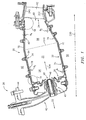
- FIG. 1 shows an exemplary combustor 20 positioned between compressor and turbine sections 22 and 24 of a gas turbine engine 26 having a central longitudinal axis or centerline 500 (spacing contracted).
- the exemplary combustor includes an annular combustion chamber 30 bounded by inner (inboard) and outer (outboard) walls 32 and 34 and a forward bulkhead 36 spanning between the walls.
- the bulkhead carries a circumferential array of swirlers 40 and associated fuel injectors 42.
- the exemplary fuel injectors extend through the engine case 44 to convey fuel from an external source to the associated inj ector outlet 46 at the associated swirler 40.
- the swirler outlet 48 thus serves as an upstream fuel/air inlet to the combustor.
- a number of sparkplugs (not shown) are positioned with their working ends along an upstream portion 54 of the combustion chamber 30 to initiate combustion of the fuel/air mixture.
- the combusting mixture is driven downstream within the combustor along a principal flowpath 504 through a downstream portion 56 to a combustor outlet 60 immediately ahead of a turbine fixed vane stage 62.
- the exemplary walls 32 and 34 are double structured, having respective outer shells 70 and 72 and inner heat shields.
- the exemplary heat shields are formed as multiple circumferential arrays (rings) of panels (e.g., inboard fore and aft panels 74 and 76 and outboard fore and aft panels 78 and 80).
- Exemplary panel and shell material are high temperature or refractory metal superalloys optionally coated with a thermal and/or environmental coating. Alternate materials include ceramics and ceramic matrix composites. Various known or other materials and manufacturing techniques may be utilized.
- the panels may be secured to the associated shells such as by means of threaded studs 84 integrally formed with the panels and supporting major portions of the panels with major portions of their exterior surfaces facing and spaced apart from the interior surface of the associated shell.
- the exemplary shells and panels are foraminate, passing cooling air from annular chambers 90 and 92 respectively inboard and outboard of the walls 32 and 34 into the combustion chamber 30.
- the exemplary panels may be configured so that the intact portions of their inboard surfaces are substantially frustoconical. Viewed in longitudinal section, these surfaces appear as straight lines at associated angles to the axis 500.
- the interior surface panel of inboard fore panel 74 is aftward/downstream diverging relative to the axis 500 at an angle ⁇ 1 .
- the interior surface of the inboard aft panel 76 is similarly diverging at a greater angle ⁇ 2 .
- the interior surface of the fore outboard panel 78 is aftward/downstream diverging at a very small angle ⁇ 3 .
- the interior surface of the aft outboard panel 80 is very close to longitudinal, shown aftward/downstream converging at a small angle ⁇ 4 .
- angles ⁇ 1 and ⁇ 3 are such that the cross-section of the chamber upstream portion 54 is approximately constant in terms of linear sectional dimension but aftward/downstream diverging along the central flowpath in terms of annular cross sectional area.
- the chamber downstream portion 56 is convergent, although at a much lesser rate.
- the junctions between fore and aft panels substantially define a dividing area 510 between fore and aft combustion chamber portions 54 and 56.
- Exemplary values for ⁇ 1 , ⁇ 2 , ⁇ 3 , and ⁇ 4 are:11.894°, 29.074°, 11.894°, and 0.785°, respectively.
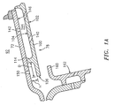
- FIGS. 1A and 2 show further details of the exemplary fore outboard panel 78 (the fore inboard panel 74 being generally similarly formed).
- the panel has a main body portion 100 having interior (hot-facing the combustion chamber) and exterior (cold-facing away from the combustion chamber) surfaces 102 and 104 (FIG. 1A).
- the body is circumscribed by a perimeter having leading and trailing portions 106 and 108 and connecting lateral portions 110 and 112 (FIG. 2).
- a rail system extends from the exterior surface 104 and includes a first portion 114 recessed from the leading edge by a distance D (FIG. 1A).
- the distal rim portions of the rail system contacts the shell interior surface so that the portions of the rail system have a height H coincident with the separation between major portions of the panel exterior surface and shell interior surface.
- Exemplary values for D and H are 3.8 mm and 1.7 mm.
- the rail system further includes a second portion 116 along the trailing edge, lateral perimeter portions 118 and 120 along the lateral edges 110 and 112, and intermediate longitudinal rails 122, 124, and 126.
- the rail system also includes portions 130 and 131 surrounding combustion process air (mixing/dilution) apertures or orifices 132 and 133 which provide direct communication through aligned corresponding apertures in the associated shell to introduce air from the associated chamber 92 or 90 into the combustion chamber to lean the combustion gases.
- the first orifices 132 are larger than the second orifices 133. These orifices circumferentially alternate along the panel.
- the respective large and small orifices of the inboard panels are exactly out of phase with those of the outboard panels. Accordingly, a large orifice of one panel will be circumferentially aligned with a small orifice of the other. This creates intermeshing air streams which further enhances mixing within the combustor.
- the panels further include arrays of film cooling holes 140 extending between the surfaces 104 and 102 (FIG. 1A). In the illustrated embodiment, air is passed through holes 142 in the shell 72 to impingement cooling spaces 144 between the shell interior surface 146 and the panel body exterior surface 104.
- the shell 72 further includes a group of holes 150 positioned between the leading edge 106 and rail portion 114. These holes are positioned so that their discharge impacts the surface 104 ahead of the rail 114 and flows forward, wrapping around the leading edge 106 and then aftward between the surface 102 and an adj acent portion 160 of a heat shield panel 162 on the bulkhead.
- the holes 150 serve to initiate film cooling along the panel interior surface and are discussed in further detail below.
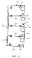
- FIGS. 1B and 3 show further details of the aft outboard heat shield panel 80 (the aft inboard panel may be similar). Many details may be similar to those of the fore panel and, therefore, are not discussed in as great length.
- the panel 80 has a body 180 with interior and exterior surfaces 182 and 184 and leading, trailing, and two lateral edges 186, 188, 190, and 192.
- the exemplary panel has a rail system with portions along the leading and lateral edges, intermediate longitudinal portions, and a portion 200 forwardly recessed from the trailing edge 188 by a distance D 2 .
- the rail system may have a similar height as with the fore panel.
- Exemplary values for D are 12.4 mm for an outboard panel and 8.7 mm for an inboard panel in the exemplary configuration.
- the choice of D 2 will be based on how close the last row of cooling holes can be placed to the combustor exit. This, in turn, is largely determined by combus tor exit sealing geometry and the nature of the drilling tool to be used. In the exemplary embodiment, such consideration places the holes farther forward of the aft panel trailing edge along the outboard wall than along the inboard wall, thus the diameter difference.
- an array of pins 202 extend from the exterior surface 184 toward and contacting the shell interior surface. In the exemplary embodiment, the pin array extends aft from approximately a midpoint of this region.
- the pin array is substantially uninterrupted and includes multiple rows (e.g., four) with the pins of each row being offset (e.g., exactly out of phase) from the pins of the adjacent rows.
- a chamber 204 is formed between the pin array and the rail portion 190. This space is fed with air from the chamber 92 through holes 206 extending at an angle ⁇ 5 to the local shell surface.
- An exemplary ⁇ 5 is 46.955°.
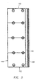
- FIG. 4 shows an exterior surface 210 of the outboard shell 72.
- the view shows process air apertures 212 and 213, respectively, coextensive with the associated apertures 132 and 133 of FIG. 2 and circular and elongate mounting apertures 214 and 215 accommodating the panel mounting studs 84 (shown with nuts removed for purposes of illustration).
- the circular apertures 214 serve to register the central pair of studs of each associated panel while the elongate nature of the holes 215 accommodate lateral pairs to permit local circumferential relative movement upon thermal expansion/contraction of elements.
- FIG. 4 shows exemplary single-row arrays of the holes 150 and 206.
- the row of holes 150 is divided into two alternating groups of holes 220 and 222.
- the holes of these exemplary groups are of substantially equal cross-section.
- the on-center spacing of the first group is smaller (e.g., 30%-70%) to provide an associated region of enhanced flow.
- Each of these enhanced flow regions is aligned between an associated pair of the fuel injectors/swirlers to provide enhanced cooling to counter the concentration of heat generated immediately downstream of overlapping spray zones such injector/swirlers.
- the number of holes in the first group is smaller than that in the second group and the circumferential span of the first group is much smaller than that of the second (e.g., less than 30% and, more narrowly, less than 20%).
- Exemplary diameters for these holes are 0.6 mm.
- Exemplary on-center spacing of the first and second groups is 1.8 mm and 3.5 mm Other permutations of spacing, size, shape, and the like may be utilized as may be variations of such parameters within groups.
- the row of holes 206 is divided into groups 230 and 232, respectively, providing more and less concentrated cooling.
- Each enhanced flow group 230 is associated with a corresponding vane 234 of the stage 62.
- the positioning of this group along with the associated angle ⁇ 5 (FIG. 1B) relative to the shell interior surface may be used to substantially counteract a bow wave of the vane 234.
- the bow wave or "horseshoe vortex" results from the interaction of the combustor output with the vane 234.
- As flow from the combustor approaches the vane leading edge 238 (which may be coincident or nearly coincident with the forward extremity 236) it stagnates at the leading edge to form a localized region of high static pressure.
- the number, shape, and angling of the holes/passageways 206 helps to direct and meter the flow (subject to having sufficient numbers and size of pins) to provide desired cooling performance while having sufficient velocity and mass flow to counter the bow wave yet not having so great a mass flow so as to constitute an excessive inefficiency.
- the exemplary group 230 is positioned ahead of the forwardmost extremity 236 of the vane airfoil, shifted slightly toward the pressure side thereof.
- the circumferential spacing of vanes 234 is much smaller than that of the fuel injectors and, accordingly, the circumferential length of the pairs of hole groups are correspondingly smaller.
- the circumferential span of the groups 230 and 232 may be nearly equal.
- Flow concentration is achieved, in the exemplary embodiment, by having larger cross-section holes in the group 230 as well as having a smaller on-center spacing in that group.
- Exemplary diameter and on-center spacing for the holes of the groups 230 are 1.0 mm and 5.9 mm for an outboard panel and 1.0 mm and 5.1 mm for an inboard panel.
- Exemplary diameter and on-center spacing for the holes of the groups 232 are 1.4 mm and 3.1 mm for an outboard panel and 1.3 mm and 3.3 mm for an inboard panel.
- An exemplary circumferential span of the first group is between 60 and 150% that of the second, more narrowly, 80 and 120%.
Landscapes
- Engineering & Computer Science (AREA)
- Chemical & Material Sciences (AREA)
- Combustion & Propulsion (AREA)
- Mechanical Engineering (AREA)
- General Engineering & Computer Science (AREA)
- Turbine Rotor Nozzle Sealing (AREA)
- Gas Burners (AREA)
Priority Applications (1)
| Application Number | Priority Date | Filing Date | Title |
|---|---|---|---|
| EP08021515.5A EP2034244B1 (de) | 2003-10-23 | 2004-10-01 | Verbrennungsanlage |
Applications Claiming Priority (2)
| Application Number | Priority Date | Filing Date | Title |
|---|---|---|---|
| US691790 | 2003-10-23 | ||
| US10/691,790 US7363763B2 (en) | 2003-10-23 | 2003-10-23 | Combustor |
Related Child Applications (2)
| Application Number | Title | Priority Date | Filing Date |
|---|---|---|---|
| EP08021515.5A Division EP2034244B1 (de) | 2003-10-23 | 2004-10-01 | Verbrennungsanlage |
| EP08021515.5 Division-Into | 2008-12-11 |
Publications (3)
| Publication Number | Publication Date |
|---|---|
| EP1528322A2 true EP1528322A2 (de) | 2005-05-04 |
| EP1528322A3 EP1528322A3 (de) | 2005-06-08 |
| EP1528322B1 EP1528322B1 (de) | 2011-05-18 |
Family
ID=34423319
Family Applications (2)
| Application Number | Title | Priority Date | Filing Date |
|---|---|---|---|
| EP04256079A Expired - Lifetime EP1528322B1 (de) | 2003-10-23 | 2004-10-01 | Brennkammer |
| EP08021515.5A Expired - Lifetime EP2034244B1 (de) | 2003-10-23 | 2004-10-01 | Verbrennungsanlage |
Family Applications After (1)
| Application Number | Title | Priority Date | Filing Date |
|---|---|---|---|
| EP08021515.5A Expired - Lifetime EP2034244B1 (de) | 2003-10-23 | 2004-10-01 | Verbrennungsanlage |
Country Status (3)
| Country | Link |
|---|---|
| US (2) | US7363763B2 (de) |
| EP (2) | EP1528322B1 (de) |
| JP (1) | JP4087375B2 (de) |
Cited By (18)
| Publication number | Priority date | Publication date | Assignee | Title |
|---|---|---|---|---|
| WO2006120204A1 (de) * | 2005-05-13 | 2006-11-16 | Siemens Aktiengesellschaft | Brennkammerwand, gasturbinenanlage und verfahren zum an- oder abfahren einer gasturbinenanlage |
| EP1939529A1 (de) | 2006-12-22 | 2008-07-02 | Deutsches Zentrum für Luft- und Raumfahrt e.V. | CMC-Brennkammerauskleidung in Doppelschichtbauweise |
| EP1998115A1 (de) * | 2007-05-29 | 2008-12-03 | Siemens Aktiengesellschaft | Kühlkanal zum Kühlen einer ein Heißgas führenden Komponente |
| EP1801502A3 (de) * | 2005-12-22 | 2010-07-07 | United Technologies Corporation | Doppelwandige Brennkammerwand |
| DE102011089242A1 (de) * | 2011-12-20 | 2013-06-20 | Siemens Aktiengesellschaft | Verbrennungssystem mit zwei Ringbrennkammern |
| WO2015084444A1 (en) | 2013-12-06 | 2015-06-11 | United Technologies Corporation | Gas turbine engine wall assembly interface |
| EP3034944A1 (de) | 2014-12-19 | 2016-06-22 | Rolls-Royce Deutschland Ltd & Co KG | Gasturbinenbrennkammer mit veränderter wandstärke |
| EP3296510A3 (de) * | 2016-09-13 | 2018-04-11 | Rolls-Royce Corporation | Additiv abgeschiedene gasturbinenmotorkühlkomponente |
| EP2647800A3 (de) * | 2012-04-03 | 2018-04-11 | General Electric Company | Verbrennungssystem mit Übergangsdüse |
| CN109340825A (zh) * | 2018-09-20 | 2019-02-15 | 西北工业大学 | 一种采用新型凸壁斜孔的燃烧室火焰筒壁面 |
| US10450871B2 (en) | 2015-02-26 | 2019-10-22 | Rolls-Royce Corporation | Repair of dual walled metallic components using directed energy deposition material addition |
| US10478920B2 (en) | 2014-09-29 | 2019-11-19 | Rolls-Royce Corporation | Dual wall components for gas turbine engines |
| US10766105B2 (en) | 2015-02-26 | 2020-09-08 | Rolls-Royce Corporation | Repair of dual walled metallic components using braze material |
| US11090771B2 (en) | 2018-11-05 | 2021-08-17 | Rolls-Royce Corporation | Dual-walled components for a gas turbine engine |
| US11098899B2 (en) | 2018-01-18 | 2021-08-24 | Raytheon Technologies Corporation | Panel burn through tolerant shell design |
| US11305363B2 (en) | 2019-02-11 | 2022-04-19 | Rolls-Royce Corporation | Repair of through-hole damage using braze sintered preform |
| US12036627B2 (en) | 2018-03-08 | 2024-07-16 | Rolls-Royce Corporation | Techniques and assemblies for joining components |
| EP4528163A1 (de) * | 2023-09-22 | 2025-03-26 | RTX Corporation | Schwebende wand mit erhöhtem prallfilm für einen gasturbinenmotor |
Families Citing this family (117)
| Publication number | Priority date | Publication date | Assignee | Title |
|---|---|---|---|---|
| US7093441B2 (en) * | 2003-10-09 | 2006-08-22 | United Technologies Corporation | Gas turbine annular combustor having a first converging volume and a second converging volume, converging less gradually than the first converging volume |
| US7140185B2 (en) * | 2004-07-12 | 2006-11-28 | United Technologies Corporation | Heatshielded article |
| EP1650503A1 (de) * | 2004-10-25 | 2006-04-26 | Siemens Aktiengesellschaft | Verfahren zur Kühlung eines Hitzeschildelements und Hitzeschildelement |
| US7587901B2 (en) | 2004-12-20 | 2009-09-15 | Amerigon Incorporated | Control system for thermal module in vehicle |
| US7954325B2 (en) * | 2005-12-06 | 2011-06-07 | United Technologies Corporation | Gas turbine combustor |
| GB2441342B (en) * | 2006-09-01 | 2009-03-18 | Rolls Royce Plc | Wall elements with apertures for gas turbine engine components |
| US20080087316A1 (en) | 2006-10-12 | 2008-04-17 | Masa Inaba | Thermoelectric device with internal sensor |
| US7681398B2 (en) * | 2006-11-17 | 2010-03-23 | Pratt & Whitney Canada Corp. | Combustor liner and heat shield assembly |
| US7748221B2 (en) * | 2006-11-17 | 2010-07-06 | Pratt & Whitney Canada Corp. | Combustor heat shield with variable cooling |
| US7721548B2 (en) * | 2006-11-17 | 2010-05-25 | Pratt & Whitney Canada Corp. | Combustor liner and heat shield assembly |
| GB2440990B (en) * | 2007-01-09 | 2008-08-06 | Cvon Innovations Ltd | Message scheduling system |
| US7845174B2 (en) * | 2007-04-19 | 2010-12-07 | Pratt & Whitney Canada Corp. | Combustor liner with improved heat shield retention |
| US7577433B2 (en) * | 2007-06-18 | 2009-08-18 | Cvon Innovations Limited | Method and system for managing delivery of communications |
| FR2918443B1 (fr) * | 2007-07-04 | 2009-10-30 | Snecma Sa | Chambre de combustion comportant des deflecteurs de protection thermique de fond de chambre et moteur a turbine a gaz en etant equipe |
| WO2009036077A1 (en) | 2007-09-10 | 2009-03-19 | Amerigon, Inc. | Operational control schemes for ventilated seat or bed assemblies |
| FR2921463B1 (fr) * | 2007-09-26 | 2013-12-06 | Snecma | Chambre de combustion d'une turbomachine |
| EP3121060A1 (de) | 2008-02-01 | 2017-01-25 | Gentherm Incorporated | Kondensations- und feuchtigkeitssensoren für thermoelektrische vorrichtungen |
| EP2341800B8 (de) | 2008-07-18 | 2012-12-26 | Gentherm Incorporated | Klimatisierte bettanordnung |
| US7886991B2 (en) * | 2008-10-03 | 2011-02-15 | General Electric Company | Premixed direct injection nozzle |
| US20100095679A1 (en) * | 2008-10-22 | 2010-04-22 | Honeywell International Inc. | Dual wall structure for use in a combustor of a gas turbine engine |
| US20100095680A1 (en) * | 2008-10-22 | 2010-04-22 | Honeywell International Inc. | Dual wall structure for use in a combustor of a gas turbine engine |
| US8266914B2 (en) * | 2008-10-22 | 2012-09-18 | Pratt & Whitney Canada Corp. | Heat shield sealing for gas turbine engine combustor |
| US8435007B2 (en) * | 2008-12-29 | 2013-05-07 | Rolls-Royce Corporation | Hybrid turbomachinery component for a gas turbine engine |
| US20100242483A1 (en) * | 2009-03-30 | 2010-09-30 | United Technologies Corporation | Combustor for gas turbine engine |
| US8448416B2 (en) * | 2009-03-30 | 2013-05-28 | General Electric Company | Combustor liner |
| US8695322B2 (en) * | 2009-03-30 | 2014-04-15 | General Electric Company | Thermally decoupled can-annular transition piece |
| US8910481B2 (en) * | 2009-05-15 | 2014-12-16 | United Technologies Corporation | Advanced quench pattern combustor |
| US8739546B2 (en) * | 2009-08-31 | 2014-06-03 | United Technologies Corporation | Gas turbine combustor with quench wake control |
| US8443610B2 (en) | 2009-11-25 | 2013-05-21 | United Technologies Corporation | Low emission gas turbine combustor |
| US9416970B2 (en) * | 2009-11-30 | 2016-08-16 | United Technologies Corporation | Combustor heat panel arrangement having holes offset from seams of a radially opposing heat panel |
| US9068751B2 (en) * | 2010-01-29 | 2015-06-30 | United Technologies Corporation | Gas turbine combustor with staged combustion |
| US8966877B2 (en) | 2010-01-29 | 2015-03-03 | United Technologies Corporation | Gas turbine combustor with variable airflow |
| US8359865B2 (en) | 2010-02-04 | 2013-01-29 | United Technologies Corporation | Combustor liner segment seal member |
| US8359866B2 (en) * | 2010-02-04 | 2013-01-29 | United Technologies Corporation | Combustor liner segment seal member |
| CH703105A1 (de) | 2010-05-05 | 2011-11-15 | Alstom Technology Ltd | Gasturbine mit einer sekundärbrennkammer. |
| US8943835B2 (en) * | 2010-05-10 | 2015-02-03 | General Electric Company | Gas turbine engine combustor with CMC heat shield and methods therefor |
| EP2428647B1 (de) | 2010-09-08 | 2018-07-11 | Ansaldo Energia IP UK Limited | Übergangsbereich für eine Brennkammer einer Gasturbine |
| US9121414B2 (en) | 2010-11-05 | 2015-09-01 | Gentherm Incorporated | Low-profile blowers and methods |
| US9010121B2 (en) | 2010-12-10 | 2015-04-21 | Rolls-Royce Plc | Combustion chamber |
| US20120180492A1 (en) * | 2011-01-14 | 2012-07-19 | General Electric Company | Apparatus for vibration support in combustors and method for forming apparatus |
| US8479521B2 (en) | 2011-01-24 | 2013-07-09 | United Technologies Corporation | Gas turbine combustor with liner air admission holes associated with interspersed main and pilot swirler assemblies |
| US9068748B2 (en) | 2011-01-24 | 2015-06-30 | United Technologies Corporation | Axial stage combustor for gas turbine engines |
| US9958162B2 (en) | 2011-01-24 | 2018-05-01 | United Technologies Corporation | Combustor assembly for a turbine engine |
| US10317081B2 (en) | 2011-01-26 | 2019-06-11 | United Technologies Corporation | Fuel injector assembly |
| DE102011012414A1 (de) | 2011-02-25 | 2012-08-30 | Rolls-Royce Deutschland Ltd & Co Kg | Gasturbinenbrennkammer |
| US8745988B2 (en) | 2011-09-06 | 2014-06-10 | Pratt & Whitney Canada Corp. | Pin fin arrangement for heat shield of gas turbine engine |
| US9685599B2 (en) | 2011-10-07 | 2017-06-20 | Gentherm Incorporated | Method and system for controlling an operation of a thermoelectric device |
| JP5821553B2 (ja) * | 2011-11-11 | 2015-11-24 | 株式会社Ihi | RQL方式の低NOx燃焼器 |
| CN102497755B (zh) * | 2011-12-20 | 2015-05-27 | 百度在线网络技术(北京)有限公司 | 机柜装置 |
| US9989267B2 (en) | 2012-02-10 | 2018-06-05 | Gentherm Incorporated | Moisture abatement in heating operation of climate controlled systems |
| DE102012204103A1 (de) * | 2012-03-15 | 2013-09-19 | Siemens Aktiengesellschaft | Hitzeschildelement für einen Verdichterluftbypass um die Brennkammer |
| US9950382B2 (en) * | 2012-03-23 | 2018-04-24 | Pratt & Whitney Canada Corp. | Method for a fabricated heat shield with rails and studs mounted on the cold side of a combustor heat shield |
| US9239165B2 (en) * | 2012-06-07 | 2016-01-19 | United Technologies Corporation | Combustor liner with convergent cooling channel |
| DE102012213637A1 (de) * | 2012-08-02 | 2014-02-06 | Siemens Aktiengesellschaft | Brennkammerkühlung |
| WO2014052966A1 (en) * | 2012-09-28 | 2014-04-03 | United Technologies Corporation | Combustor section of a gas turbine engine |
| EP2900970B1 (de) | 2012-09-30 | 2018-12-05 | United Technologies Corporation | Schnittstellenhitzeschild für einen verbrenner eines gasturbinentriebwerks |
| CN102901126B (zh) * | 2012-10-26 | 2015-01-14 | 中国航空动力机械研究所 | 燃烧组织结构 |
| US9958160B2 (en) | 2013-02-06 | 2018-05-01 | United Technologies Corporation | Gas turbine engine component with upstream-directed cooling film holes |
| WO2014189556A2 (en) | 2013-02-08 | 2014-11-27 | United Technologies Corporation | Gas turbine engine combustor liner assembly with convergent hyperbolic profile |
| EP2965010B1 (de) | 2013-03-05 | 2018-10-17 | Rolls-Royce Corporation | Zweiwandige prallkühlungs-, konvektions- und effusions-brennkammerkachel |
| US10914470B2 (en) | 2013-03-14 | 2021-02-09 | Raytheon Technologies Corporation | Combustor panel with increased durability |
| US20160033129A1 (en) * | 2013-03-14 | 2016-02-04 | United Technologies Corporation | Additive manufactured gas turbine engine combustor liner panel |
| WO2014149108A1 (en) | 2013-03-15 | 2014-09-25 | Graves Charles B | Shell and tiled liner arrangement for a combustor |
| US10634351B2 (en) | 2013-04-12 | 2020-04-28 | United Technologies Corporation | Combustor panel T-junction cooling |
| US9494081B2 (en) | 2013-05-09 | 2016-11-15 | Siemens Aktiengesellschaft | Turbine engine shutdown temperature control system with an elongated ejector |
| US20150033746A1 (en) * | 2013-08-02 | 2015-02-05 | Solar Turbines Incorporated | Heat shield with standoffs |
| EP2837887B1 (de) * | 2013-08-15 | 2019-06-12 | Ansaldo Energia Switzerland AG | Brennkammer einer Gasturbine mit Druckverlust für optimierte Verkleidungskühlung |
| US10488046B2 (en) * | 2013-08-16 | 2019-11-26 | United Technologies Corporation | Gas turbine engine combustor bulkhead assembly |
| US10168052B2 (en) | 2013-09-04 | 2019-01-01 | United Technologies Corporation | Combustor bulkhead heat shield |
| US20150059349A1 (en) * | 2013-09-04 | 2015-03-05 | Pratt & Whitney Canada Corp. | Combustor chamber cooling |
| EP3922829B1 (de) | 2013-09-16 | 2023-11-08 | RTX Corporation | Gasturbinenbrennkammerwandung mit kühlungslöchern durch eine transversale struktur |
| EP3047128B1 (de) | 2013-09-16 | 2018-10-31 | United Technologies Corporation | Kontrollierte variation des druckabfalls durch effusionskühlung in einer doppelwandigen brennkammer eines gasturbinentriebwerks |
| US10047958B2 (en) | 2013-10-07 | 2018-08-14 | United Technologies Corporation | Combustor wall with tapered cooling cavity |
| EP3055530B1 (de) | 2013-10-07 | 2020-08-12 | United Technologies Corporation | Gebundene brennkammerwand für einen turbinenmotor |
| US20160238249A1 (en) * | 2013-10-18 | 2016-08-18 | United Technologies Corporation | Combustor wall having cooling element(s) within a cooling cavity |
| EP3060847B1 (de) | 2013-10-24 | 2019-09-18 | United Technologies Corporation | Durchgangsgeometrie für eine gasturbinenbrennkammer |
| US10240790B2 (en) | 2013-11-04 | 2019-03-26 | United Technologies Corporation | Turbine engine combustor heat shield with multi-height rails |
| US10215410B2 (en) | 2013-11-04 | 2019-02-26 | United Technologies Corporation | Turbine engine combustor heat shield with multi-angled cooling apertures |
| US10571125B2 (en) | 2013-11-04 | 2020-02-25 | United Technologies Corporation | Quench aperture body for a turbine engine combustor |
| WO2015065579A1 (en) * | 2013-11-04 | 2015-05-07 | United Technologies Corporation | Gas turbine engine wall assembly with offset rail |
| US9662962B2 (en) | 2013-11-05 | 2017-05-30 | Gentherm Incorporated | Vehicle headliner assembly for zonal comfort |
| WO2015122950A2 (en) * | 2013-11-21 | 2015-08-20 | United Technologies Corporation | Turbine engine multi-walled structure with internal cooling element(s) |
| EP3084310A4 (de) * | 2013-12-19 | 2017-01-04 | United Technologies Corporation | Gasturbinenmotorwandanordnung mit umlaufender schienenbolzenarchitektur |
| EP3099976B1 (de) * | 2014-01-30 | 2019-03-13 | United Technologies Corporation | Kühlfluss für führungspaneel in einer gasturbinenbrennkammer |
| WO2015123585A1 (en) | 2014-02-14 | 2015-08-20 | Gentherm Incorporated | Conductive convective climate controlled seat |
| US9752447B2 (en) * | 2014-04-04 | 2017-09-05 | United Technologies Corporation | Angled rail holes |
| US9625152B2 (en) * | 2014-06-03 | 2017-04-18 | Pratt & Whitney Canada Corp. | Combustor heat shield for a gas turbine engine |
| US10731857B2 (en) * | 2014-09-09 | 2020-08-04 | Raytheon Technologies Corporation | Film cooling circuit for a combustor liner |
| US20160265777A1 (en) * | 2014-10-17 | 2016-09-15 | United Technologies Corporation | Modified floatwall panel dilution hole cooling |
| US11639816B2 (en) | 2014-11-14 | 2023-05-02 | Gentherm Incorporated | Heating and cooling technologies including temperature regulating pad wrap and technologies with liquid system |
| US11857004B2 (en) | 2014-11-14 | 2024-01-02 | Gentherm Incorporated | Heating and cooling technologies |
| US11033058B2 (en) | 2014-11-14 | 2021-06-15 | Gentherm Incorporated | Heating and cooling technologies |
| US10132498B2 (en) * | 2015-01-20 | 2018-11-20 | United Technologies Corporation | Thermal barrier coating of a combustor dilution hole |
| US10267521B2 (en) | 2015-04-13 | 2019-04-23 | Pratt & Whitney Canada Corp. | Combustor heat shield |
| GB201514390D0 (en) | 2015-08-13 | 2015-09-30 | Rolls Royce Plc | A combustion chamber and a combustion chamber segment |
| GB201518345D0 (en) * | 2015-10-16 | 2015-12-02 | Rolls Royce | Combustor for a gas turbine engine |
| GB201603166D0 (en) * | 2016-02-24 | 2016-04-06 | Rolls Royce Plc | A combustion chamber |
| US10215411B2 (en) * | 2016-03-07 | 2019-02-26 | United Technologies Corporation | Combustor panels having recessed rail |
| DE102016206188A1 (de) * | 2016-04-13 | 2017-10-19 | Rolls-Royce Deutschland Ltd & Co Kg | Brennkammerschindel einer Gasturbine |
| GB201610122D0 (en) * | 2016-06-10 | 2016-07-27 | Rolls Royce Plc | A combustion chamber |
| US10386067B2 (en) * | 2016-09-15 | 2019-08-20 | United Technologies Corporation | Wall panel assembly for a gas turbine engine |
| US10830433B2 (en) | 2016-11-10 | 2020-11-10 | Raytheon Technologies Corporation | Axial non-linear interface for combustor liner panels in a gas turbine combustor |
| US10655853B2 (en) | 2016-11-10 | 2020-05-19 | United Technologies Corporation | Combustor liner panel with non-linear circumferential edge for a gas turbine engine combustor |
| US10935235B2 (en) | 2016-11-10 | 2021-03-02 | Raytheon Technologies Corporation | Non-planar combustor liner panel for a gas turbine engine combustor |
| US20180230602A1 (en) * | 2016-11-10 | 2018-08-16 | United Technologies Corporation | Coated combustor panel shell for a gas turbine engine combustor |
| DE102016222099A1 (de) * | 2016-11-10 | 2018-05-17 | Rolls-Royce Deutschland Ltd & Co Kg | Brennkammer einer Gasturbine |
| US10935236B2 (en) | 2016-11-10 | 2021-03-02 | Raytheon Technologies Corporation | Non-planar combustor liner panel for a gas turbine engine combustor |
| US10935243B2 (en) * | 2016-11-30 | 2021-03-02 | Raytheon Technologies Corporation | Regulated combustor liner panel for a gas turbine engine combustor |
| US10634353B2 (en) * | 2017-01-12 | 2020-04-28 | General Electric Company | Fuel nozzle assembly with micro channel cooling |
| US10941939B2 (en) * | 2017-09-25 | 2021-03-09 | General Electric Company | Gas turbine assemblies and methods |
| US20200035898A1 (en) | 2018-07-30 | 2020-01-30 | Gentherm Incorporated | Thermoelectric device having circuitry that facilitates manufacture |
| US11181269B2 (en) | 2018-11-15 | 2021-11-23 | General Electric Company | Involute trapped vortex combustor assembly |
| JP7608337B2 (ja) | 2018-11-30 | 2025-01-06 | ジェンサーム インコーポレイテッド | 熱電調整システム及び方法 |
| US11152557B2 (en) | 2019-02-20 | 2021-10-19 | Gentherm Incorporated | Thermoelectric module with integrated printed circuit board |
| US11047575B2 (en) * | 2019-04-15 | 2021-06-29 | Raytheon Technologies Corporation | Combustor heat shield panel |
| US11293638B2 (en) * | 2019-08-23 | 2022-04-05 | Raytheon Technologies Corporation | Combustor heat shield and method of cooling same |
| US20210372616A1 (en) * | 2020-05-27 | 2021-12-02 | Raytheon Technologies Corporation | Multi-walled structure for a gas turbine engine |
Family Cites Families (18)
| Publication number | Priority date | Publication date | Assignee | Title |
|---|---|---|---|---|
| GB2087065B (en) * | 1980-11-08 | 1984-11-07 | Rolls Royce | Wall structure for a combustion chamber |
| JPH0660740B2 (ja) * | 1985-04-05 | 1994-08-10 | 工業技術院長 | ガスタービンの燃焼器 |
| DE3615226A1 (de) * | 1986-05-06 | 1987-11-12 | Mtu Muenchen Gmbh | Heissgasueberhitzungsschutzeinrichtung fuer gasturbinentriebwerke |
| FR2624953B1 (fr) | 1987-12-16 | 1990-04-20 | Snecma | Chambre de combustion, pour turbomachines, possedant un convergent a doubles parois |
| US5435139A (en) | 1991-03-22 | 1995-07-25 | Rolls-Royce Plc | Removable combustor liner for gas turbine engine combustor |
| US5363643A (en) * | 1993-02-08 | 1994-11-15 | General Electric Company | Segmented combustor |
| GB9305010D0 (en) * | 1993-03-11 | 1993-04-28 | Rolls Royce Plc | A cooled turbine nozzle assembly and a method of calculating the diameters of cooling holes for use in such an assembly |
| FR2714152B1 (fr) | 1993-12-22 | 1996-01-19 | Snecma | Dispositif de fixation d'une tuile de protection thermique dans une chambre de combustion. |
| US5758503A (en) | 1995-05-03 | 1998-06-02 | United Technologies Corporation | Gas turbine combustor |
| US5782294A (en) | 1995-12-18 | 1998-07-21 | United Technologies Corporation | Cooled liner apparatus |
| FR2752916B1 (fr) | 1996-09-05 | 1998-10-02 | Snecma | Chemise de protection thermique pour chambre de combustion de turboreacteur |
| US6240731B1 (en) | 1997-12-31 | 2001-06-05 | United Technologies Corporation | Low NOx combustor for gas turbine engine |
| GB9926257D0 (en) | 1999-11-06 | 2000-01-12 | Rolls Royce Plc | Wall elements for gas turbine engine combustors |
| GB2361303B (en) | 2000-04-14 | 2004-10-20 | Rolls Royce Plc | Wall structure for a gas turbine engine combustor |
| US6606861B2 (en) | 2001-02-26 | 2003-08-19 | United Technologies Corporation | Low emissions combustor for a gas turbine engine |
| US6701714B2 (en) * | 2001-12-05 | 2004-03-09 | United Technologies Corporation | Gas turbine combustor |
| US7093439B2 (en) | 2002-05-16 | 2006-08-22 | United Technologies Corporation | Heat shield panels for use in a combustor for a gas turbine engine |
| US7146815B2 (en) * | 2003-07-31 | 2006-12-12 | United Technologies Corporation | Combustor |
-
2003
- 2003-10-23 US US10/691,790 patent/US7363763B2/en not_active Expired - Lifetime
-
2004
- 2004-10-01 EP EP04256079A patent/EP1528322B1/de not_active Expired - Lifetime
- 2004-10-01 EP EP08021515.5A patent/EP2034244B1/de not_active Expired - Lifetime
- 2004-10-20 JP JP2004305071A patent/JP4087375B2/ja not_active Expired - Fee Related
-
2008
- 2008-02-26 US US12/037,128 patent/US8015829B2/en active Active
Cited By (31)
| Publication number | Priority date | Publication date | Assignee | Title |
|---|---|---|---|---|
| WO2006120204A1 (de) * | 2005-05-13 | 2006-11-16 | Siemens Aktiengesellschaft | Brennkammerwand, gasturbinenanlage und verfahren zum an- oder abfahren einer gasturbinenanlage |
| EP1724526A1 (de) * | 2005-05-13 | 2006-11-22 | Siemens Aktiengesellschaft | Brennkammerschale, Gasturbinenanlage und Verfahren zum An- oder Abfahren einer Gasturbinenanlage |
| US8091364B2 (en) | 2005-05-13 | 2012-01-10 | Siemens Aktiengesellschaft | Combustion chamber wall, gas turbine installation and process for starting or shutting down a gas turbine installation |
| EP1801502A3 (de) * | 2005-12-22 | 2010-07-07 | United Technologies Corporation | Doppelwandige Brennkammerwand |
| EP1939529A1 (de) | 2006-12-22 | 2008-07-02 | Deutsches Zentrum für Luft- und Raumfahrt e.V. | CMC-Brennkammerauskleidung in Doppelschichtbauweise |
| EP1998115A1 (de) * | 2007-05-29 | 2008-12-03 | Siemens Aktiengesellschaft | Kühlkanal zum Kühlen einer ein Heißgas führenden Komponente |
| DE102011089242A1 (de) * | 2011-12-20 | 2013-06-20 | Siemens Aktiengesellschaft | Verbrennungssystem mit zwei Ringbrennkammern |
| EP2647800A3 (de) * | 2012-04-03 | 2018-04-11 | General Electric Company | Verbrennungssystem mit Übergangsdüse |
| WO2015084444A1 (en) | 2013-12-06 | 2015-06-11 | United Technologies Corporation | Gas turbine engine wall assembly interface |
| EP3077729A4 (de) * | 2013-12-06 | 2017-01-11 | United Technologies Corporation | Schnittstelle für gasturbinenmotorwandanordnung |
| US10478920B2 (en) | 2014-09-29 | 2019-11-19 | Rolls-Royce Corporation | Dual wall components for gas turbine engines |
| EP3034944A1 (de) | 2014-12-19 | 2016-06-22 | Rolls-Royce Deutschland Ltd & Co KG | Gasturbinenbrennkammer mit veränderter wandstärke |
| DE102014226707A1 (de) | 2014-12-19 | 2016-06-23 | Rolls-Royce Deutschland Ltd & Co Kg | Gasturbinenbrennkammer mit veränderter Wandstärke |
| US10450871B2 (en) | 2015-02-26 | 2019-10-22 | Rolls-Royce Corporation | Repair of dual walled metallic components using directed energy deposition material addition |
| US10766105B2 (en) | 2015-02-26 | 2020-09-08 | Rolls-Royce Corporation | Repair of dual walled metallic components using braze material |
| US12157192B2 (en) | 2015-02-26 | 2024-12-03 | Rolls-Royce Corporation | Repair of dual walled metallic components using braze material |
| US11731218B2 (en) | 2015-02-26 | 2023-08-22 | Rolls-Royce Corporation | Repair of dual walled metallic components using braze material |
| EP3296510A3 (de) * | 2016-09-13 | 2018-04-11 | Rolls-Royce Corporation | Additiv abgeschiedene gasturbinenmotorkühlkomponente |
| US11248491B2 (en) | 2016-09-13 | 2022-02-15 | Rolls-Royce Corporation | Additively deposited gas turbine engine cooling component |
| US11719439B2 (en) | 2018-01-18 | 2023-08-08 | Raythehon Technologies Corporation | Panel burn through tolerant shell design |
| US11098899B2 (en) | 2018-01-18 | 2021-08-24 | Raytheon Technologies Corporation | Panel burn through tolerant shell design |
| EP3537046B1 (de) * | 2018-01-18 | 2022-05-04 | Raytheon Technologies Corporation | Doppelwandiges flammrohre für ein gasturbinentriebwerk |
| US12036627B2 (en) | 2018-03-08 | 2024-07-16 | Rolls-Royce Corporation | Techniques and assemblies for joining components |
| CN109340825A (zh) * | 2018-09-20 | 2019-02-15 | 西北工业大学 | 一种采用新型凸壁斜孔的燃烧室火焰筒壁面 |
| US11541488B2 (en) | 2018-11-05 | 2023-01-03 | Rolls-Royce Corporation | Dual-walled components for a gas turbine engine |
| US11090771B2 (en) | 2018-11-05 | 2021-08-17 | Rolls-Royce Corporation | Dual-walled components for a gas turbine engine |
| US12194580B2 (en) | 2018-11-05 | 2025-01-14 | Rolls-Royce Corporation | Dual-walled components for a gas turbine engine |
| US11305363B2 (en) | 2019-02-11 | 2022-04-19 | Rolls-Royce Corporation | Repair of through-hole damage using braze sintered preform |
| US11731206B2 (en) | 2019-02-11 | 2023-08-22 | Rolls-Royce Corporation | Repair of through-hole damage using braze sintered preform |
| EP4528163A1 (de) * | 2023-09-22 | 2025-03-26 | RTX Corporation | Schwebende wand mit erhöhtem prallfilm für einen gasturbinenmotor |
| US12352441B2 (en) | 2023-09-22 | 2025-07-08 | Rtx Corporation | Reinforced film floatwall for a gas turbine engine |
Also Published As
| Publication number | Publication date |
|---|---|
| EP2034244B1 (de) | 2016-04-06 |
| US20050086940A1 (en) | 2005-04-28 |
| JP4087375B2 (ja) | 2008-05-21 |
| US20090293488A1 (en) | 2009-12-03 |
| EP1528322B1 (de) | 2011-05-18 |
| JP2005127705A (ja) | 2005-05-19 |
| US7363763B2 (en) | 2008-04-29 |
| US8015829B2 (en) | 2011-09-13 |
| EP1528322A3 (de) | 2005-06-08 |
| EP2034244A1 (de) | 2009-03-11 |
Similar Documents
| Publication | Publication Date | Title |
|---|---|---|
| EP1528322B1 (de) | Brennkammer | |
| US7093441B2 (en) | Gas turbine annular combustor having a first converging volume and a second converging volume, converging less gradually than the first converging volume | |
| CN109196279B (zh) | 具有面板式燃料喷射器的燃烧系统 | |
| JP7146442B2 (ja) | 二重燃料噴射器およびガスタービン燃焼器での使用方法 | |
| US7966822B2 (en) | Reverse-flow gas turbine combustion system | |
| US8800290B2 (en) | Combustor | |
| US9759426B2 (en) | Combustor nozzles in gas turbine engines | |
| US8752386B2 (en) | Air/fuel supply system for use in a gas turbine engine | |
| US7670108B2 (en) | Air seal unit adapted to be positioned adjacent blade structure in a gas turbine | |
| US20110239654A1 (en) | Angled seal cooling system | |
| EP2971970B1 (de) | Dublettenbrenner mit gegenwirbel | |
| US11320146B2 (en) | Film cooling a combustor wall of a turbine engine | |
| US10830448B2 (en) | Combustor liner panel with a multiple of heat transfer augmentors for a gas turbine engine combustor | |
| US20120304654A1 (en) | Combustion liner having turbulators | |
| US20160169522A1 (en) | Fuel injector guide(s) for a turbine engine combustor | |
| US11193672B2 (en) | Combustor quench aperture cooling | |
| US20180238546A1 (en) | Combustor liner panel end rail cooling enhancement features for a gas turbine engine combustor | |
| US11668463B2 (en) | Combustor with dilution holes | |
| US10697636B2 (en) | Cooling a combustor heat shield proximate a quench aperture | |
| US12259133B2 (en) | Cooling combustor wall boss | |
| EP3321584B1 (de) | Gasturbinenmotorbrennkammer mit einer axial-nichtplanaren brennkammerverkleidungsplatte | |
| EP3321585B1 (de) | Nichtplanare brennkammerverkleidungsplatte für eine gasturbinenmotorbrennkammer | |
| US10655853B2 (en) | Combustor liner panel with non-linear circumferential edge for a gas turbine engine combustor |
Legal Events
| Date | Code | Title | Description |
|---|---|---|---|
| PUAI | Public reference made under article 153(3) epc to a published international application that has entered the european phase |
Free format text: ORIGINAL CODE: 0009012 |
|
| PUAL | Search report despatched |
Free format text: ORIGINAL CODE: 0009013 |
|
| AK | Designated contracting states |
Kind code of ref document: A2 Designated state(s): AT BE BG CH CY CZ DE DK EE ES FI FR GB GR HU IE IT LI LU MC NL PL PT RO SE SI SK TR |
|
| AX | Request for extension of the european patent |
Extension state: AL HR LT LV MK |
|
| AK | Designated contracting states |
Kind code of ref document: A3 Designated state(s): AT BE BG CH CY CZ DE DK EE ES FI FR GB GR HU IE IT LI LU MC NL PL PT RO SE SI SK TR |
|
| AX | Request for extension of the european patent |
Extension state: AL HR LT LV MK |
|
| 17P | Request for examination filed |
Effective date: 20050915 |
|
| AKX | Designation fees paid |
Designated state(s): DE FR GB |
|
| 17Q | First examination report despatched |
Effective date: 20080110 |
|
| GRAP | Despatch of communication of intention to grant a patent |
Free format text: ORIGINAL CODE: EPIDOSNIGR1 |
|
| GRAS | Grant fee paid |
Free format text: ORIGINAL CODE: EPIDOSNIGR3 |
|
| GRAA | (expected) grant |
Free format text: ORIGINAL CODE: 0009210 |
|
| REG | Reference to a national code |
Ref country code: DE Ref legal event code: R081 Ref document number: 602004032710 Country of ref document: DE Owner name: UNITED TECHNOLOGIES CORP. (N.D.GES.D. STAATES , US Free format text: FORMER OWNER: UNITED TECHNOLOGIES CORP. (N.D.GES.D. STAATES DELAWARE), HARTFORD, CONN., US |
|
| AK | Designated contracting states |
Kind code of ref document: B1 Designated state(s): DE FR GB |
|
| REG | Reference to a national code |
Ref country code: GB Ref legal event code: FG4D |
|
| REG | Reference to a national code |
Ref country code: DE Ref legal event code: R096 Ref document number: 602004032710 Country of ref document: DE Effective date: 20110630 |
|
| PLBE | No opposition filed within time limit |
Free format text: ORIGINAL CODE: 0009261 |
|
| STAA | Information on the status of an ep patent application or granted ep patent |
Free format text: STATUS: NO OPPOSITION FILED WITHIN TIME LIMIT |
|
| 26N | No opposition filed |
Effective date: 20120221 |
|
| REG | Reference to a national code |
Ref country code: DE Ref legal event code: R097 Ref document number: 602004032710 Country of ref document: DE Effective date: 20120221 |
|
| REG | Reference to a national code |
Ref country code: FR Ref legal event code: ST Effective date: 20120629 |
|
| PG25 | Lapsed in a contracting state [announced via postgrant information from national office to epo] |
Ref country code: FR Free format text: LAPSE BECAUSE OF NON-PAYMENT OF DUE FEES Effective date: 20111102 |
|
| REG | Reference to a national code |
Ref country code: DE Ref legal event code: R082 Ref document number: 602004032710 Country of ref document: DE Representative=s name: SCHMITT-NILSON SCHRAUD WAIBEL WOHLFROM PATENTA, DE |
|
| REG | Reference to a national code |
Ref country code: DE Ref legal event code: R082 Ref document number: 602004032710 Country of ref document: DE Representative=s name: SCHMITT-NILSON SCHRAUD WAIBEL WOHLFROM PATENTA, DE Ref country code: DE Ref legal event code: R081 Ref document number: 602004032710 Country of ref document: DE Owner name: UNITED TECHNOLOGIES CORP. (N.D.GES.D. STAATES , US Free format text: FORMER OWNER: UNITED TECHNOLOGIES CORPORATION, HARTFORD, CONN., US |
|
| PGFP | Annual fee paid to national office [announced via postgrant information from national office to epo] |
Ref country code: DE Payment date: 20190918 Year of fee payment: 16 |
|
| REG | Reference to a national code |
Ref country code: DE Ref legal event code: R119 Ref document number: 602004032710 Country of ref document: DE |
|
| PG25 | Lapsed in a contracting state [announced via postgrant information from national office to epo] |
Ref country code: DE Free format text: LAPSE BECAUSE OF NON-PAYMENT OF DUE FEES Effective date: 20210501 |
|
| PGFP | Annual fee paid to national office [announced via postgrant information from national office to epo] |
Ref country code: GB Payment date: 20230920 Year of fee payment: 20 |
|
| PG25 | Lapsed in a contracting state [announced via postgrant information from national office to epo] |
Ref country code: GB Free format text: LAPSE BECAUSE OF EXPIRATION OF PROTECTION Effective date: 20240930 |
|
| REG | Reference to a national code |
Ref country code: GB Ref legal event code: PE20 Expiry date: 20240930 |
|
| PG25 | Lapsed in a contracting state [announced via postgrant information from national office to epo] |
Ref country code: GB Free format text: LAPSE BECAUSE OF EXPIRATION OF PROTECTION Effective date: 20240930 |