EP1528314A2 - Vehicle headlamp with connection support for a lockable lamp - Google Patents
Vehicle headlamp with connection support for a lockable lamp Download PDFInfo
- Publication number
- EP1528314A2 EP1528314A2 EP04292524A EP04292524A EP1528314A2 EP 1528314 A2 EP1528314 A2 EP 1528314A2 EP 04292524 A EP04292524 A EP 04292524A EP 04292524 A EP04292524 A EP 04292524A EP 1528314 A2 EP1528314 A2 EP 1528314A2
- Authority
- EP
- European Patent Office
- Prior art keywords
- reflector
- connection support
- connection
- locking
- projector device
- Prior art date
- Legal status (The legal status is an assumption and is not a legal conclusion. Google has not performed a legal analysis and makes no representation as to the accuracy of the status listed.)
- Granted
Links
Images


Classifications
-
- F—MECHANICAL ENGINEERING; LIGHTING; HEATING; WEAPONS; BLASTING
- F21—LIGHTING
- F21V—FUNCTIONAL FEATURES OR DETAILS OF LIGHTING DEVICES OR SYSTEMS THEREOF; STRUCTURAL COMBINATIONS OF LIGHTING DEVICES WITH OTHER ARTICLES, NOT OTHERWISE PROVIDED FOR
- F21V19/00—Fastening of light sources or lamp holders
-
- F—MECHANICAL ENGINEERING; LIGHTING; HEATING; WEAPONS; BLASTING
- F21—LIGHTING
- F21S—NON-PORTABLE LIGHTING DEVICES; SYSTEMS THEREOF; VEHICLE LIGHTING DEVICES SPECIALLY ADAPTED FOR VEHICLE EXTERIORS
- F21S41/00—Illuminating devices specially adapted for vehicle exteriors, e.g. headlamps
- F21S41/10—Illuminating devices specially adapted for vehicle exteriors, e.g. headlamps characterised by the light source
- F21S41/19—Attachment of light sources or lamp holders
- F21S41/192—Details of lamp holders, terminals or connectors
Definitions
- the present invention relates to a projector device equipped with a connection bracket for lock lamp. It is essentially for purpose of proposing a projector device some of which is used as mounting surface of a connection support. Said connection support is mounted in such a way that it guarantees a simple positioning correct means of electrical connection (or connector), a source light having counterparts of said connection means in cavities formed in said support: the goal is to ensure a correct and reliable electrical connection between these means of electrical connections and their counterparts.
- bimodal projectors which combine the functions of low beam and long range lights: for this purpose, it is possible in particular to arrange inside the dual-mode projector a DFCS type light source (for Double Filament adapted to Complex Surfaces), which has two filaments separate, a first filament being dedicated to a use of the source bright as a passing light, and a second filament being dedicated use of the light source as high beam.
- DFCS type light source for Double Filament adapted to Complex Surfaces
- the set of projectors that have just been mentioned comprise at least one light source and a reflector comprising at least least one optical system, each optical system being composed each at least one light source associated with a reflector composed of a or more reflective surfaces whose layout and orientation are defined to produce a particular light beam.
- the operation fixing the light source on the reflector poses a number difficulties in assembling the projector device, especially since so-called "one touch" fixing operations are now preferred for fixation of the DFCS type light sources.
- Fixing operations say “one touch”, which can result in simplified fixing operation, are operations that consist in realizing the fixation of the source light on the reflector in a single operation, decomposable into one translational movement, to introduce the bulb of the light source through a cavity at the top of the reflector, combined with a rotation, to lock the light source on the reflector.
- Mechanical fastening and electrical connection can, and preferably must, be simultaneously ensured by the simplified fixing operation.
- connection support present in the invention intervenes in the framework of these simplified fixation operations. Although these operations simplification are, for the time being, mainly intended for light sources DFCS, the projector device according to the invention is not limited to these light sources only, but concerns all previously mentioned projectors, even those not using DFCS light sources, which are likely to use the Simplified fixation previously mentioned.
- the connection support present in the invention can intervene in all the projectors equipped with light sources the connection means are arranged radially, whether by example of DFCS light sources, or standard lamps of the type H8, H9 or H11.
- the light source 200 essentially comprises a bulb 201, dotted, fixed on a support 202.
- the support 202 is, for its part, consisting of a first cylindrical portion 203, on which is fixed the bulb 201 and whose apex is centered on a lower face of a second cylindrical portion 204, itself terminated by a gripping means 205 of the light source 200 which allows to manipulate the latter.
- the second cylindrical portion 204 is wider than the first portion cylindrical 203. It comprises, on its side wall, a set of connecting tabs 206. On the side wall of the first part 203, a set of locking lugs 207 has been arranged.
- the flexible blades 209 follow the circular shape of the zone 208. They have a first end 210 cut into the thickness of the zone 208, and a second end 211, said free end, which exceeds slightly from the plane defined by zone 208.
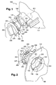
- the reflector 100 consists of an outer face 101, visible at the Figure 1, and an inner face 102; the reflector 100 having been subjected, at the Figure 2, a section for the purposes of the description, the inner face 102 is visible on this figure.
- the inner face 102 is also called optical surface of the reflector: it is she who is responsible for reflecting the light rays emitted by the light source 200 when the latter is fixed on the reflector 100 and that the bulb 201 radiates.
- the reflector 100 has a circular opening 103 arranged approximately at its summit.
- the opening 103 is arranged at one end of a termination, or flange, 104 of the reflector 100, said termination 104 being of cylindrical shape.
- a bearing surface 105 We dispose thus, around the opening 103, a bearing surface 105.
- the bearing surface 105 has an inner face 106, belonging to to the inner face 102 of the reflector 100, and an outer face 107 belonging to the outer face 101 of the reflector 100.
- the bearing surface 105 has approximately the shape of a ring in the center of which one finds the circular opening 103.
- the circular opening 103 is completed by clearances 108 which are intended to let the legs of locking 207 of the light source 200 in the cylindrical terminal 104.
- the simplified fixing operation of the light source 200 on the reflector 100 can be broken down into two distinct movements: a first movement, called introductory, consists of a translation according to the optical axis of the light source 200 to the reflector 100 so that the bulb 201 is introduced into the circular opening 103 of the reflector 200.
- the arrangement of the light source during the introductory movement is such that the locking lugs 207 are arranged facing the clearances 108 that complete the circular opening 103 so they can also be introduced inside the reflector 100.
- the flexible blades 209 are in contact with the outer face 107 of the bearing surface 105.
- the dimensions of the bearing surface 105 and the zone 208 are preferably, similar and parallel to each other.
- the locking step consists of a rotational movement, in a plane defined by the bearing surface 105, of the light source 200, with respect to the reflector 100. Different steps of this movement are detailed with reference to FIG.
- At least one boss 400 is disposed on the outer face 107 of the support surface 105.
- three bosses can be provided, evenly spaced on the bearing surface 105.
- the bosses 400 allow an installer to locate the end of the lock operation of the light source 200 on the reflector 100.
- the free ends 211 of the flexible blades 209, and more particularly their protuberance 305, are used as protrusion for locating the bosses.
- the light source 200 has an inertial effect to complete the lock: indeed, the movement is mechanically accelerated after passing from the top of the 400.
- the acceleration phase must, according to the standards in force, mark the end of the locking movement.
- the passage bosses 400 is performed simultaneously with the insertion of each connecting tab 206 in a holding member 302 corresponding, each holding member 302 being disposed on the face 107 of the bearing surface 105 of the reflector 100 at a position adequate to receive the connecting tab 206 which is intended for it.
- the holding elements 302 may for example be clips, it is at elastic members which, by deformation when mating, allow the realization of a mechanical connection, and possibly a electrical connection.
- each connection tab 206 is inserted into the clip 302 which is intended; simultaneously, at least one locking tab 207, and in particular each locking tab 207, meets a stop 304, disposed at a suitable position on the inner face 106 of the surface 105 so that each locking tab 207 is in contact with a stop 304 disposed on the reflector 100, which is specifically intended, when the locking position is reached.
- the protrusions 305 of the blades hoses 209 are supported on the zone 208. Their function is to maintain the light source 200 bearing on the inner face 106.
- the bosses 400 provide a anti-return effect which blocks the light source 200 in the position of locking by preventing a rotational movement in one direction antagonist to the locking direction 300 can be performed without a significant external contribution.
- Cavities 401 may be provided in zone 208, at the level each free end 211.
- the free ends 211 supporting the protuberances 305 can, if necessary, rise slightly above the level of zone 208 to ensure the permanent alignment of connecting tabs 206 and holding members 302, even when the protuberances 305 reach the top of the bosses 400. holding elements 302 are not deformed during the crossing bosses, which guarantees their sustainable use and, where appropriate, optimal electrical conduction.
- the following elements - the stops 304, the bosses 400, the clearances 108, the flexible blades 209 and the legs of locking 207 - are divided into three sets of fasteners, each set of elements comprising one of these elements, elements being arranged in such a way that they can cooperate to achieve a fastening system operating according to the mechanism that has just been described.
- the connection tabs 206 are also three in number.
- Another locking solution known in the state of the art consists of having the bosses on the inner face 106 and not on the outer face 107. But such a solution has as a major disadvantage that the passage of the bosses is done by means of the legs of lock, which are not flexible; axial displacement of the source 200 luminous relative to the reflector 100 is then inevitable, training a misalignment of the connection tabs with respect to the elements of 302, which distorts the latter during the introduction of the connecting tabs.
- connection support it is proposed to make a part intermediate which constitutes a connection support to receive the whole connecting tabs 206; the connection support is a part monobloc in which are made as many counterparts as there are connecting tabs 206 to be connected.
- connection support is made of several parts which are pre assembled to trap the clips 302 during the final assembly.
- the connection support is removable: it is arranged on a part of the reflector, in the vicinity of the flange 104, after molding said reflector, and can be easily removed later, for example to be replaced by a new connection medium with a number different from counterparts.
- connection support is fixed on the reflector on anchor points integrated into the reflector, and whose realization did not complicate the realization of the reflector, no drawer addition that was necessary during the operations of molding / demolding of the reflector.
- connection medium can present different ways to ensure that it is arranged in a position optimal for receiving the connection tabs connecting electric light source.
- Said projector device comprises a removable connection support intended to be fixed on the external face of the reflector, said support connection comprising a set of counterparts of means of electrical connection, also called counterpart of means of connections, to ensure, in a locked position, an electrical connection with the connection tabs following a locking operation of the light source on the reflector.
- Another object of the invention is a motor vehicle equipped with a projector device having the main features and one or many of the secondary features just mentioned. Another object of the invention relates to the reflector described above, another object of the invention relates to the connection support described above, a Another object of the invention relates to the light source described above.
- connection support 500 shows a first embodiment of a connection support 500 that can be used in the projector device according to the invention.
- the connection support 500 shown in plan view, is a part manufactured independently of reflector 100 and the light source 200. It can therefore be in a material different from that used for the realization of these parts.
- the connection support 500 is made in a plastic material.
- connection support 500 has an imposed circular arc shape by the arrangement of the connection tabs 206. It includes, in its thickness, a set of cavities 501 intended to each receive a connecting tab 206. For the sake of simplification of the figures, a cavity 501 has been shown in FIG. 4. In practice, the connection support 500 has at least as many cavities 501 as there are connection tabs 206 on the light source 200, the most economical solution to provide connection media 500 with exactly the number of cavities 501 that there are tabs However, it may be interesting to install in devices projectors connection supports with cavities that first remain unused, the light source 100 thus able to evolve and be replaced by a new light source having more connection tabs 206, the tabs of additional connections that can be introduced into cavities unused until then ..
- the cavities are L-shaped.
- first end 502 is intended to receive an electrical wire 503 from a general power connection means for the projector device.
- a second end 504 is open: an opening 510, visible in the figure 5 which is a sectional view, according to the projection A, of the cavity 501, allows introducing inside the cavity 501, a connection tongue during the operation of introducing the light source into the opening 103 by a translation movement.
- connection support 500 In each cavity 501, a counterpart of connection 505, which corresponds to reference 302 in FIG. connection means 505 serves to pinch the connection tab 206 at the end of the rotational movement of the light source 200 by relative to the reflector 100.
- the counterparts of the connection means are in addition in contact with the electrical wire 503 to feed the source light.
- connection support 500 has a hole 506 arranged at one of its extremities. It also features a tongue of 507 lock, disposed at its other end, said free end, two spring blades 508 and a locking tab 509 whose functions are present in reference to FIG. 6.
- the reflector 100 comprises, close to the flange 104, a rotation pivot 600, completed by a thinner end 601 for housing in the hole 506 of the 500 connection support.
- the connection support 500 can thus be placed by translational movement on the reflector 100 in a position not locked, shown in phantom in Figure 7.
- the support connection 500 can then be brought into the locked position, represented in solid lines, by a displacement in rotation DD 'around the pivot 600.
- the locking tab 509 is introduced into a cavity 603 formed in the collar 104.
- the leg of block 509 extends horizontally in the plane of rotation. Once introduced into the cavity 603, it therefore prevents the connection support 500 to move in translation along the optical axis; any movement in rotation being made impossible by the retention pin 602, the support of connection 500 is, in its locked position, perfectly blocked.
- the spring blades 508 are arranged so that they come press, deforming, on the flange 104 at the end of the movement of locking. If the lock is not correctly performed, ie if the locking tab 507 has not totally exceeded the pin of retention 602, the blades spring 508, by the pressure they exert on the flange 104, push back the connection support 500 in one direction opposed to the locking direction, thus clearly showing that the locking was not done correctly.
- the locking tab 509 is disposed between the leaf spring 508 as an exemplary embodiment.
- Figures 8 and 9 show a second embodiment of the projector device according to the invention.
- the rotation pivot 600 of the first example is replaced by holding elements 800 arranged on the reflector 100, close to the flange 104.
- the holding elements are guide rails which extend parallel to the optical axis. These guide rails cooperate with complementary slides 801 arranged on the support connection 500 to bring the connection support into position locked only by a translation movement parallel to the axis optical.
- the connection media no longer has hole 506, neither leaf spring 508 nor lock tab 507.
- the locking tab 509 is still present.
- Figure 9 which is a sectional view of the projection according to the direction referenced A on FIG.
- the locking tab consists of a first thin portion 900 extending along the flange 104, outside the latter, and a second part 901, constituted by a lug, a hook, extending perpendicular to the first part.
- the locking tab 509 is slightly deformed to slide on the outer face of the flange 104 until the lug 901 arrives in a cavity 902 in which it is introduced by elasticity of the locking tab 509. The connection support is thus blocked in its locked position.
- Figures 10, 11 and 12 show a third embodiment of the projector device according to the invention.
- the holding elements 800 arranged on the reflector 100, close to the flange 104 are fastening studs which extend parallel to the optical axis.
- These fixing studs cooperate with the hole 506, already present in the first example described, and with a second hole 1000 disposed on the opposite end of the connection support 500 to that having the first hole 506, as seen in Figure 11; this figure is a sectional view of the projection in the direction referenced B on the Figure 10 of the locked position.
- Both holes 506 and 1000 replace the complementary slides 801 of the second example described. We can still bring the connection support 500 in its locked position only by a translation movement parallel to the optical axis.
- the locking tab 509 is still present. As we see in Figure 12, which is a sectional view of the projection according to the direction referenced A in FIG. 10, it is always constituted of a first fine portion 1200 extending along the flange 104, but within the latter, and a second part 1201, constituted by a lug, a hook, extending perpendicular to the first part. During the locking movement by translation, the locking tab 509 is therefore slightly deformed to slide on the inner face of the flange 104 until the pin 1201 arrives in a cavity 1202 in which it is introduced by elasticity of the locking tab 509. The connection support is thus locked in its locked position.
- the legs of Block 509 can be interchanged: the one used in the second example of realization can be used in the third, and that used in the third embodiment can be used in the second.
- the locking tab 509 is introduced from the inside of the collar 104, one can use as cavity 1202 one of the clearances 108 completing the opening 103 which is provided with the flange 104 of the reflector 100.
- the clearance 108 is then substantially extended so as to be able to simultaneously let pass a locking tab 207 and the leg of blocking 509.
- cavities 501 having counterparts 505 of means of connections have not been shown only for the sake of clarity of the figures.
- the different elements added for the purpose of the invention on the reflector 100 namely the pivot in rotation 600, the retention lug 602, or the various examples of elements of maintain 800 extend parallel to the optical axis, without cavity in their body; they do not require the addition of drawers in the mold used to make the reflector.
- connection support 500 completely surround the flange 104.
- the connection support 500 is then an approximately circular piece, which is arranged in translation on the reflector 100. It can in particular be maintained by means of two locking tabs, of the type shown in the examples previously described; in a particular example, the two legs of blocking are diametrically opposed.
Landscapes
- Engineering & Computer Science (AREA)
- General Engineering & Computer Science (AREA)
- Non-Portable Lighting Devices Or Systems Thereof (AREA)
Abstract
Description
La présente invention a pour objet un dispositif projecteur équipé d'un support de connexion pour lampe à verrouillage. Elle a essentiellement pour but de proposer un dispositif projecteur dont une partie est utilisée comme surface de fixation d'un support de connexion. Ledit support de connexion est monté de telle sorte qu'il garantit de façon simple un positionnement correct des moyens de connexion électrique (ou connecteur), d'une source lumineuse comportant des contre-parties desdits moyens de connexion électrique dans des cavités ménagées dans ledit support : le but est d'assurer une connexion électrique correcte et fiable entre ces moyens de connexion électriques et leur contre-parties.The present invention relates to a projector device equipped with a connection bracket for lock lamp. It is essentially for purpose of proposing a projector device some of which is used as mounting surface of a connection support. Said connection support is mounted in such a way that it guarantees a simple positioning correct means of electrical connection (or connector), a source light having counterparts of said connection means in cavities formed in said support: the goal is to ensure a correct and reliable electrical connection between these means of electrical connections and their counterparts.
Le domaine de l'invention est, d'une façon générale, celui des projecteurs de véhicule automobile. Dans ce domaine, on connaít différents types de projecteurs, parmi lesquels on trouve essentiellement :
- des feux de position, d'intensité et de portée faible ;
- des feux de croisement, ou de code, d'intensité plus forte et de portée sur la route avoisinant 70 mètres, qui sont utilisés essentiellement la nuit et dont la répartition du faisceau lumineux est telle qu'elle permet de ne pas éblouir le conducteur d'un véhicule croisé ;
- des feux de route longue portée, et des feux de complément de type longue portée, dont la zone de vision sur la route avoisine 200 mètres, et qui doivent être éteints lorsque l'on croise un autre véhicule afin de ne pas éblouir son conducteur ;
- des feux anti-brouillard.
- position, intensity and low range lights;
- low beam, or higher intensity, range and range lights on the road of approximately 70 meters, which are mainly used at night and whose light beam distribution is such that it does not dazzle the driver. a crossed vehicle;
- long-range headlamps, and long-range supplement lights, whose vision zone on the road is approximately 200 meters, and which must be extinguished when crossing another vehicle so as not to dazzle its driver;
- fog lights.
Par ailleurs, on connaít certains projecteurs perfectionnés, appelés projecteurs bimodes, qui cumulent les fonctions de feux de croisement et de feux longue portée : à cet effet, on peut notamment disposer à l'intérieur du projecteur bimode une source lumineuse de type DFCS (pour Double Filament adapté aux Surfaces Complexes), qui comporte deux filaments distincts, un premier filament étant dédié à une utilisation de la source lumineuse en tant que feu de croisement, et un second filament étant dédié à une utilisation de la source lumineuse en tant que feu de route.Moreover, we know some advanced projectors, called bimodal projectors, which combine the functions of low beam and long range lights: for this purpose, it is possible in particular to arrange inside the dual-mode projector a DFCS type light source (for Double Filament adapted to Complex Surfaces), which has two filaments separate, a first filament being dedicated to a use of the source bright as a passing light, and a second filament being dedicated use of the light source as high beam.
L'ensemble des dispositifs projecteurs qui viennent d'être mentionnés comprennent au moins une source lumineuse et un réflecteur comportant au moins un système optique, chaque système optique étant composé chacun d'au moins une source lumineuse associée à un réflecteur composé d'une ou plusieurs surfaces réfléchissantes dont la disposition et l'orientation sont définies de manière à produire un faisceau lumineux particulier. L'opération de fixation de la source lumineuse sur le réflecteur pose un certain nombre de difficultés lors de l'assemblage du dispositif projecteur, d'autant plus que des opérations de fixation dites "one touch" sont désormais privilégiées pour la fixation des sources lumineuses de type DFCS. Les opérations de fixation dites "one touch", qui peut se traduire par opération de fixation simplifiée, sont des opérations qui consistent à réaliser la fixation de la source lumineuse sur le réflecteur en une opération unique, décomposable en un mouvement de translation, pour introduire l'ampoule de la source lumineuse au travers d'une cavité ménagée au sommet du réflecteur, combiné à un mouvement de rotation, pour effectuer le verrouillage de la source lumineuse sur le réflecteur. La solidarisation mécanique et la connexion électrique peuvent, et de préférence doivent, être simultanément assurées par l'opération de fixation simplifiée.The set of projectors that have just been mentioned comprise at least one light source and a reflector comprising at least least one optical system, each optical system being composed each at least one light source associated with a reflector composed of a or more reflective surfaces whose layout and orientation are defined to produce a particular light beam. The operation fixing the light source on the reflector poses a number difficulties in assembling the projector device, especially since so-called "one touch" fixing operations are now preferred for fixation of the DFCS type light sources. Fixing operations say "one touch", which can result in simplified fixing operation, are operations that consist in realizing the fixation of the source light on the reflector in a single operation, decomposable into one translational movement, to introduce the bulb of the light source through a cavity at the top of the reflector, combined with a rotation, to lock the light source on the reflector. Mechanical fastening and electrical connection can, and preferably must, be simultaneously ensured by the simplified fixing operation.
Le support de connexion présent dans l'invention intervient dans le cadre de ces opérations de fixation simplifiée. Bien que ces opérations de fixation simplifiée soient, pour le moment, essentiellement destinées aux sources lumineuses DFCS, le dispositif projecteur selon l'invention n'est pas limité à ces seules sources lumineuses, mais concerne l'ensemble des dispositifs projecteurs précédemment cités, même ceux n'utilisant pas de sources lumineuses DFCS, qui sont susceptibles de recourir à l'opération de fixation simplifiée précédemment mentionnée. D'une façon générale, le support de connexion présent dans l'invention peut intervenir dans l'ensemble des dispositifs projecteurs équipés de sources lumineuses dont les moyens de connexion sont disposés radialement, qu'il s'agisse par exemple de sources lumineuses DFCS, ou des lampes normalisées de type H8, H9 ou H11.The connection support present in the invention intervenes in the framework of these simplified fixation operations. Although these operations simplification are, for the time being, mainly intended for light sources DFCS, the projector device according to the invention is not limited to these light sources only, but concerns all previously mentioned projectors, even those not using DFCS light sources, which are likely to use the Simplified fixation previously mentioned. In general, the connection support present in the invention can intervene in all the projectors equipped with light sources the connection means are arranged radially, whether by example of DFCS light sources, or standard lamps of the type H8, H9 or H11.
Initialement, les moyens de connexion électrique des lampes d'éclairages étaient sur des languettes saillantes disposées parallèlement à l'axe optique sur les culots de ces lampes ; l'opération de connexion électrique n'était donc pas effectuée simultanément à la fixation mécanique, ce qui multipliait les risques de mauvais montage, notamment à cause des difficultés d'accès aux éléments à connecter. Puis, dans l'état de la technique, on a proposé le système de fixation simplifiée du type de celui illustré aux figures 1, 2 et 3. Dans l'ensemble de la description, les éléments communs à plusieurs figures seront désignés par la même référence:Initially, the means of electrical connection of the lamps lights were on protruding tabs arranged parallel to the optical axis on the caps of these lamps; the connection operation electrical power was therefore not performed simultaneously with the mechanical fastening, which multiplied the risks of bad assembly, in particular because of Difficulties of access to the elements to connect. Then, in the state of the technical, it has been proposed the simplified fixing system of the type of illustrated in Figures 1, 2 and 3. Throughout the description, the elements common to several figures will be designated by the same reference:
Sur les figures 1 et 2, on a représenté en perspective, de façon
schématique, un réflecteur 100 sur lequel on vient fixer une source
lumineuse 200.In Figures 1 and 2, there is shown in perspective, so
schematic, a
La source lumineuse 200 comporte essentiellement une ampoule 201,
représentée en pointillés, fixée sur un support 202. Le support 202 est, pour
sa part, constitué d'une première partie cylindrique 203, sur laquelle est fixée
l'ampoule 201 et dont un sommet est centré sur une face inférieure d'une
deuxième partie cylindrique 204, elle-même terminée par un moyen de saisie
205 de la source lumineuse 200 qui permet de manipuler cette dernière. La
deuxième partie cylindrique 204 est plus large que la première partie
cylindrique 203. Elle comporte, sur sa paroi latérale, un ensemble de
languettes de connexion 206. Sur la paroi latérale de la première partie
cylindrique 203, on a disposé un ensemble de pattes de verrouillage 207. La
face inférieure de la deuxième partie cylindrique 204 correspond, au niveau
de sa périphérie laissée accessible après la jonction avec la première partie
cylindrique 203, à une zone 208 du support 202. Cette zone 208 est
destinée à venir en appui sur le réflecteur 100 lorsque la fixation est
effectuée par l'intermédiaire de lames flexibles 209.The
Les lames flexibles 209 suivent la forme circulaire de la zone 208.
Elles ont une première extrémité 210 découpée dans l'épaisseur de la zone
208, et une deuxième extrémité 211, dite extrémité libre, qui dépasse
légèrement du plan défini par la zone 208.The
Le réflecteur 100 est constitué d'une face externe 101, visible à la
figure 1, et d'une face interne 102; le réflecteur 100 ayant fait l'objet, à la
figure 2, d'une coupe pour les besoins de la description, la face interne 102
est visible sur cette figure. La face interne 102 est également appelée
surface optique du réflecteur : c'est elle qui est chargée de réfléchir les
rayons lumineux émis par la source lumineuse 200 quand cette dernière est
fixée sur le réflecteur 100 et que l'ampoule 201 rayonne.The
Le réflecteur 100 comporte une ouverture circulaire 103 ménagée
approximativement à son sommet. Typiquement, l'ouverture 103 est
disposée au niveau d'une extrémité d'une terminaison, ou collerette, 104 du
réflecteur 100, ladite terminaison 104 étant de forme cylindrique. On dispose
ainsi, autour de l'ouverture 103, d'une surface d'appui 105.The
La surface d'appui 105 présente une face intérieure 106, appartenant
à la face interne 102 du réflecteur 100, et une face extérieure 107
appartenant à la face externe 101 du réflecteur 100. La surface d'appui 105
a approximativement la forme d'un anneau au centre duquel on trouve
l'ouverture circulaire 103. L'ouverture circulaire 103 est complétée par des
dégagements 108 qui sont destinés à laisser passer les pattes de
verrouillage 207 de la source lumineuse 200 dans la terminaison cylindrique
104.The
L'opération de fixation simplifiée de la source lumineuse 200 sur le
réflecteur 100 peut se décomposer en deux mouvements distincts : un
premier mouvement, dit d'introduction, consiste en une translation selon
l'axe optique de la source lumineuse 200 vers le réflecteur 100 de telle sorte
que l'ampoule 201 soit introduite dans l'ouverture circulaire 103 du réflecteur
200. La disposition de la source lumineuse lors du mouvement d'introduction
est telle que les pattes de verrouillage 207 sont disposées face aux
dégagements 108 qui complètent l'ouverture circulaire 103 de telle sorte
qu'elles peuvent également être introduites à l'intérieur du réflecteur 100. A
la fin de l'étape d'introduction, les lames flexibles 209 sont en contact avec la
face extérieur 107 de la surface d'appui 105.The simplified fixing operation of the
Les dimensions de la surface d'appui 105 et de la zone 208 sont, de
préférence, similaires et parallèles entre elles.The dimensions of the
Une fois le mouvement d'introduction achevé, on peut alors procéder
au deuxième mouvement, qui consiste à réaliser le verrouillage de la source
lumineuse 200 sur le réflecteur 100. L'étape de verrouillage consiste en un
mouvement de rotation, dans un plan défini par la surface d'appui 105, de la
source lumineuse 200, par rapport au réflecteur 100. Différentes étapes de
ce mouvement sont détaillées en se référant à la figure 3.Once the introduction movement has been completed, we can proceed
at the second movement, which consists of locking the
Sur cette figure, on a représenté, de façon schématique, une vue en
coupe d'une projection linéaire d'une partie de la surface d'appui 105 du
réflecteur 100 et des différents éléments intervenant au voisinage direct de
la surface d'appui 105 pendant l'étape de verrouillage. Une fois que les
pattes de verrouillage 207 ont été introduites au sein du réflecteur 100 par
les dégagements 108, elles sont mises en contact, dès l'amorce du
mouvement de rotation selon une direction de verrouillage 300, avec la face
intérieure 106 de la surface d'appui 105, ceci du fait de la pression des
lames flexibles 209, éventuellement par l'intermédiaire de protubérances 305
présentes au niveau de leur extrémité libre 211, sur la face externe 107 de la
surface d'appui 105. La surface d'appui 105 est ainsi pincée entre les pattes
de verrouillage 207 et la zone 208 par l'intermédiaire des lames flexibles
209.In this figure, there is shown, schematically, a view of
cutting a linear projection of a portion of the
Au moins un bossage 400 est disposé sur la face extérieure 107 de la
surface d'appui 105. On peut par exemple disposer trois bossages,
régulièrement espacés sur la surface d'appui 105. Les bossages 400
permettent à un installateur de repérer la fin de l'opération de verrouillage de
la source lumineuse 200 sur le réflecteur 100. Les extrémités libres 211 des
lames flexibles 209, et plus particulièrement leur protubérance 305, sont
utilisées comme protubérance servant à repérer les bossages.At least one
Une fois le sommet du bossage 400 passé, la source lumineuse 200
bénéficie d'un effet inertiel pour achever le verrouillage : en effet, le
mouvement est mécaniquement accéléré après le passage du sommet du
bossage 400. La phase d'accélération doit, d'après les normes en vigueur,
marquer la fin du mouvement de verrouillage. En conséquence, le passage
des bossages 400 s'effectue simultanément à l'insertion de chaque
languette de connexion 206 dans un élément de maintien 302
correspondant, chaque élément de maintien 302 étant disposé sur la face
extérieure 107 de la surface d'appui 105 du réflecteur 100 à une position
adéquate pour recevoir la languette de connexion 206 qui lui est destinée.
Les éléments de maintien 302 peuvent par exemple être des clips, c'est à
dire des organes élastiques qui, par déformation à l'accouplement,
permettent la réalisation d'une liaison mécanique, et éventuellement d'une
liaison électrique.Once the top of the
A la fin du mouvement de verrouillage, assuré par l'effet inertiel,
chaque languette de connexion 206 est insérée dans le clip 302 qui lui est
destiné ; simultanément, au moins une patte de verrouillage 207, et
notamment chaque patte de verrouillage 207, rencontre une butée 304,
disposée à une position adéquate sur la face intérieure 106 de la surface
d'appui 105 pour que chaque patte de verrouillage 207 soit en contact avec
une butée 304 disposée sur le réflecteur 100, qui lui est spécifiquement
destinée, lorsque la position de verrouillage est atteinte. Par ailleurs, lorsque
la position de verrouillage est atteinte, les protubérances 305 des lames
flexibles 209 sont en appui sur la zone 208. Leur fonction est de maintenir la
source lumineuse 200 en appui sur la face intérieure 106.At the end of the locking movement, ensured by the inertial effect,
each
Outre l'effet inertiel qu'ils procurent, les bossages 400 assurent un
effet anti-retour qui bloque la source lumineuse 200 dans la position de
verrouillage en empêchant qu'un mouvement de rotation dans une direction
antagoniste à la direction de verrouillage 300 puisse être effectué sans une
contribution extérieure significative.In addition to the inertial effect they provide, the
Des cavités 401 peuvent être ménagées dans la zone 208, au niveau
de chaque extrémité libre 211. Ainsi, les extrémités libres 211 supportant les
protubérances 305 peuvent, si nécessaire, remonter légèrement au-dessus
du niveau de la zone 208 pour garantir l'alignement permanent des
languettes de connexion 206 et des éléments de maintien 302, même quand
les protubérances 305 atteignent le sommet des bossages 400. Les
éléments de maintien 302 ne sont ainsi pas déformés lors du franchissement
des bossages, ce qui permet de leur garantir une utilisation durable et, le cas
échéant, une conduction électrique optimale.
Dans l'exemple décrit, les éléments suivants - les butées 304, les
bossages 400, les dégagements 108, les lames flexibles 209 et les pattes de
verrouillage 207 - sont répartis en trois ensembles d'éléments de fixation,
chaque ensemble d'éléments comportant un de ces éléments, lesdits
éléments étant disposés de telle sorte qu'ils peuvent coopérer pour réaliser
un système de fixation fonctionnant selon le mécanisme qui vient d'être
décrit. Les languettes de connexion 206 sont également au nombre de trois.In the example described, the following elements - the
Une autre solution de verrouillage connue dans l'état de la technique
consiste à disposer des bossages sur la face intérieure 106 et non pas sur la
face extérieure 107. Mais une telle solution a comme inconvénient majeur
que le passage des bossages s'effectue au moyen des pattes de
verrouillage, qui ne sont pas flexibles ; un déplacement axial de la source
lumineuse 200 par rapport au réflecteur 100 est alors inévitable, entraínant
un désalignement des languettes de connexion par rapport aux éléments de
maintien 302, ce qui déforme ces derniers lors de l'introduction des
languettes de connexion. Another locking solution known in the state of the art
consists of having the bosses on the
Lorsque l'on souhaite assurer la connexion électrique de la source lumineuse 200 simultanément à l'opération de verrouillage, au moins une des languettes de connexion 206 est électriquement conductrice, et le clip 302, qui est alors une contrepartie de moyen de connexion électrique, également dite contrepartie de moyen de connexion, qui lui est associé est disposé dans un élément 303. Il reçoit par ailleurs une alimentation électrique. Aucune solution satisfaisante n'existe à ce jour ; l'objet de la présente invention est donc essentiellement de proposer une solution pour que la mise en place de contre-partie de moyen de connexions, ajoutées sur le dispositif projecteur, ne complique pas excessivement la fabrication dudit dispositif projecteur, notamment :
- en ne modifiant pas de façon significative les moules utilisés pour
fabriquer le réflecteur 100
et sa terminaison 104 ; - en garantissant un espacement approprié entre chaque contre-partie de moyen de connexion, l'espacement approprié correspondant à l'espacement entre les différentes languettes de connexion 206, pour que la connexion soit optimale lors du verrouillage de la source lumineuse 200 sur le réflecteur 100. En garantissant la position exacte de l'ensemble des contre-parties de moyen de connexion, on est assuré que les languettes de connexion 206 seront parfaitement engagées dans les contre-parties de moyen de connexion lors du verrouillage de la source lumineuse.
- by not significantly modifying the molds used to manufacture the
reflector 100 and itstermination 104; - by ensuring an appropriate spacing between each counter part connection means, the appropriate spacing corresponding to the spacing between the
different connection tabs 206, for the connection to be optimal when locking thelight source 200 on thereflector 100 By guaranteeing the exact position of the set of connection means counterparts, it is ensured that the connectingtabs 206 will be fully engaged in the counterparts of connection means when locking the light source.
A cet effet, dans l'invention, on propose de réaliser une pièce
intermédiaire qui constitue un support de connexion pour recevoir l'ensemble
des languettes de connexion 206 ; le support de connexion est une pièce
monobloc dans laquelle sont ménagées autant de contre-parties qu'il y a de
languettes de connexion 206 à connecter. Dans un autre exemple de
réalisation, le support de connexion est réalisé en plusieurs parties qui sont
pré assemblées pour emprisonner les clips 302 lors de l'assemblage définitif.
Le support de connexion est amovible : il est disposé sur une partie du
réflecteur, au voisinage de la collerette 104, après le moulage dudit
réflecteur, et peut être facilement retiré par la suite, par exemple pour être
remplacé par un nouveau support de connexion comportant un nombre
différent de contre-parties. Le support de connexion vient se fixer sur le
réflecteur sur des points d'ancrage intégrés dans le réflecteur, et dont la
réalisation n'a pas compliqué la réalisation du réflecteur, aucun ajout de tiroir
supplémentaire n'ayant été nécessaire lors des opérations de
moulage/démoulage du réflecteur. En outre, le support de connexion peut
présenter différents moyens pour garantir qu'il est disposé dans une position
optimale pour recevoir les languettes de connexion assurant la connexion
électrique de la source lumineuse.For this purpose, in the invention, it is proposed to make a part
intermediate which constitutes a connection support to receive the whole
connecting
L'invention concerne donc principalement un dispositif projecteur comportant notamment :
- une source lumineuse munie d'une ampoule, d'un support d'ampoule, d'un ensemble de languettes de connexion et au moins une patte de verrouillage ;
- un réflecteur, présentant une face interne et une face externe, ledit réflecteur comportant une collerette, munie d'une ouverture circulaire complétée par un ensemble de dégagements, à proximité de laquelle la source lumineuse pince le réflecteur entre les pattes de verrouillage, en contact avec la face interne, et une zone du support en regard de la face externe du réflecteur.
- a light source provided with a bulb, a bulb holder, a set of connecting tabs and at least one locking tab;
- a reflector, having an inner face and an outer face, said reflector having a collar, provided with a circular opening completed by a set of clearances, near which the light source clamps the reflector between the locking tabs, in contact with the inner face, and an area of the support facing the outer face of the reflector.
Ledit dispositif projecteur comporte un support de connexion amovible destiné à être fixé sur la face externe du réflecteur, ledit support de connexion comportant un ensemble de contre-parties de moyens de connexion électrique, dite également contre-partie de moyen de connexions, pour assurer, dans une position verrouillée, une connexion électrique avec les languettes de connexion suite à une opération de verrouillage de la source lumineuse sur le réflecteur.Said projector device comprises a removable connection support intended to be fixed on the external face of the reflector, said support connection comprising a set of counterparts of means of electrical connection, also called counterpart of means of connections, to ensure, in a locked position, an electrical connection with the connection tabs following a locking operation of the light source on the reflector.
Le dispositif projecteur selon l'invention peut, outre les caractéristiques principales qui viennent d'être mentionnées, présenter une ou plusieurs des caractéristiques secondaires suivantes :
- le support de connexion comporte un nombre de contre-parties de moyen de connexions supérieur ou égal au nombre de languettes de connexion présentes sur la source lumineuse.
- chaque contre-partie de moyen de connexion est disposée à une extrémité fermée d'une cavité ménagée dans l'épaisseur du support de connexion, chaque languette de connexion étant amenée dans une des contre-parties de moyen de connexion par un mouvement de rotation de la source lumineuse par rapport au réflecteur lors de l'opération de verrouillage, ladite opération de verrouillage faisant suite à une opération de translation de la source lumineuse à travers l'ouverture du réflecteur au cours de laquelle chaque languette de connexion est introduite dans une des cavités du support de connexion via une extrémité ouverte de la cavité considérée.
- la face externe du réflecteur comporte un pivot de rotation sur lequel le support de connexion est positionné par translation dans une position non verrouillée, puis autour duquel le support de connexion évolue en rotation pour être placé dans la position verrouillée.
- la face externe du réflecteur comporte un ergot de rétention pour maintenir le support de connexion dans la position verrouillée en bloquant en rotation une languette de verrouillage située à une extrémité libre du support de connexion.
- le support de connexion comporte au moins une lame ressort pour repousser le support de connexion dans une direction l'éloignant de sa position verrouillée lorsque la position verrouillée n'a pas été atteinte.
- la face externe du réflecteur comporte au moins un élément de maintien pour amener le support de connexion par un mouvement de translation dans la position verrouillée.
- les éléments de maintien sont deux plots de fixation, chaque plot de fixation venant s'encastrer dans une cavité appropriée du support de connexion pour maintenir le support de connexion dans la position verrouillée.
- les éléments de maintien sont deux glissières de guidage contre lesquelles le support de connexion évolue en translation pour être positionné dans la position verrouillée.
- le support de connexion entoure partiellement ou totalement la collerette.
- le support de connexion comporte au moins une patte de blocage pour empêcher le support de connexion d'évoluer en translation une fois qu'il est placé dans la position verrouillée. Il peut s'agir d'un système de clip. Dans le cas où le support de connexion n'entoure que partiellement la collerette, seule une patte de blocage, un clip, peut suffire. Dans le cas où le support de connexion entoure complètement la collerette (son ouverture circulaire en fait), on peut avantageusement prévoir deux pattes de blocage, deux clips disposées de préférence de façon diamétralement opposée.
- la patte de blocage comporte un ergot qui, lorsque le support de connexion est dans la position verrouillée, est placé dans une cavité spécifique ménagée dans la collerette du réflecteur.
- la patte de blocage comporte un ergot qui, lorsque le support de connexion est dans la position verrouillée, est placé dans un des dégagements complétant l'ouverture dont est munie la collerette du réflecteur.
- au moins une languette de verrouillage est amenée en appui contre une butée suite à l'opération de verrouillage.
- the connection support comprises a number of connection means counterparts greater than or equal to the number of connection tabs present on the light source.
- each counterpart of connection means is disposed at a closed end of a cavity formed in the thickness of the connection support, each connecting tab being fed into one of the counterparts of connection means by a rotational movement of the light source with respect to the reflector during the locking operation, said locking operation following an operation of translation of the light source through the aperture of the reflector during which each connecting tab is introduced into one of the cavities of the connection support via an open end of the cavity considered.
- the outer face of the reflector comprises a pivot of rotation on which the connection support is positioned by translation in an unlocked position, and around which the connection support rotates to be placed in the locked position.
- the outer face of the reflector has a retention lug for holding the connection support in the locked position by locking in rotation a locking tab located at a free end of the connection support.
- the connection support comprises at least one spring blade for pushing the connection support in a direction away from its locked position when the locked position has not been reached.
- the outer face of the reflector comprises at least one holding element for bringing the connection support by a translation movement in the locked position.
- the holding elements are two fixing studs, each fixing stud being embedded in an appropriate cavity of the connection support to maintain the connection support in the locked position.
- the holding elements are two guide rails against which the connection support evolves in translation to be positioned in the locked position.
- the connection support partially or completely surrounds the collar.
- the connection support comprises at least one locking tab for preventing the connection support from moving in translation once it is placed in the locked position. It can be a clip system. In the case where the connection support only partially surrounds the flange, only a locking tab, a clip, may suffice. In the case where the connection support completely surrounds the flange (its circular opening in fact), one can advantageously provide two locking tabs, two clips preferably arranged diametrically opposite.
- the locking tab has a lug which, when the connection support is in the locked position, is placed in a specific cavity in the reflector collar.
- the locking tab comprises a lug which, when the connection support is in the locked position, is placed in one of the clearances completing the opening which is provided with the flange of the reflector.
- at least one locking tongue is brought in abutment against an abutment following the locking operation.
Un autre objet de l'invention est un véhicule automobile équipé d'un dispositif projecteur présentant les caractéristiques principales et une ou plusieurs des caractéristiques secondaires qui viennent d'être mentionnées. Un autre objet de l'invention concerne le réflecteur décrit plus haut, un autre objet de l'invention concerne le support de connexion décrit plus haut, un autre objet de l'invention concerne la source lumineuse décrite plus haut.Another object of the invention is a motor vehicle equipped with a projector device having the main features and one or many of the secondary features just mentioned. Another object of the invention relates to the reflector described above, another object of the invention relates to the connection support described above, a Another object of the invention relates to the light source described above.
L'invention et ses différentes applications seront mieux comprises à la lecture de la description qui suit et à l'examen des figures qui l'accompagnent. Celles-ci ne sont présentées qu'à titre indicatif et nullement limitatif de l'invention. Les figures montrent :
- à la figure 1, déjà décrite, une première représentation schématique d'un réflecteur sur lequel on vient fixer une source lumineuse ;
- à la figure 2, également déjà décrite, une deuxième représentation schématique d'un réflecteur sur lequel on vient fixer une source lumineuse ;
- à la figure 3, également déjà décrite, une représentation schématique d'un système de fixation d'une source lumineuse sur un réflecteur connu de l'état de la technique ;
- à la figure 4, un premier exemple de réalisation du support de connexion intervenant dans le dispositif projecteur selon l'invention ;
- à la figure 5, une représentation d'une contre-partie de moyen de connexion du support de connexion de la figure 4 ;
- à la figure 6, un premier exemple de réflecteur intervenant dans le dispositif projecteur selon l'invention ;
- à la figure 7, une illustration de l'assemblage du support de connexion de la figure 4 sur le réflecteur de la figure 6 ;
- à la figure 8, une illustration de l'assemblage d'un deuxième exemple de support de connexion et d'un deuxième exemple de réflecteur intervenant dans le dispositif selon l'invention ;
- à la figure 9, une vue en coupe de l'assemblage de la figure 8 ;
- à la figure 10, une illustration de l'assemblage d'un troisième exemple de support de connexion et d'un troisième exemple de réflecteur intervenant dans le dispositif selon l'invention ;
- à la figure 11, une première vue en coupe de l'assemblage de la figure 10 ;
- à la figure 12, une deuxième vue en coupe de l'assemblage de la figure 10.
- in Figure 1, already described, a first schematic representation of a reflector on which is fixed a light source;
- in Figure 2, also already described, a second schematic representation of a reflector on which is fixed a light source;
- in FIG. 3, also already described, a schematic representation of a system for fixing a light source on a reflector known from the state of the art;
- in Figure 4, a first embodiment of the connection medium involved in the projector device according to the invention;
- in FIG. 5, a representation of a counterpart of connection means of the connection support of FIG. 4;
- in Figure 6, a first example of reflector involved in the projector device according to the invention;
- in Figure 7, an illustration of the assembly of the connection support of Figure 4 on the reflector of Figure 6;
- in Figure 8, an illustration of the assembly of a second example of connection support and a second example of reflector involved in the device according to the invention;
- in Figure 9, a sectional view of the assembly of Figure 8;
- in Figure 10, an illustration of the assembly of a third example of connection support and a third example of a reflector involved in the device according to the invention;
- in Figure 11, a first sectional view of the assembly of Figure 10;
- in Figure 12, a second sectional view of the assembly of Figure 10.
Les éléments apparaissant dans différentes figures sont, sauf
précision contraire, désignées par les mêmes références, éventuellement
utilisées dans les figures déjà décrites. La figure 4 montre un premier
exemple de réalisation d'un support de connexion 500 utilisable dans le
dispositif projecteur selon l'invention. Le support de connexion 500,
représenté en vue de dessus, est une pièce fabriquée indépendamment du
réflecteur 100 et de la source lumineuse 200. Elle peut donc être dans un
matériau différent de celui utilisé pour la réalisation de ces pièces. Dans un
exemple particulier, le support de connexion 500 est réalisé dans une
matière plastique.The elements appearing in different figures are except
contrary precision, designated by the same references, possibly
used in the figures already described. Figure 4 shows a first
embodiment of a
Le support de connexion 500 a une forme en arc de cercle imposée
par la disposition des languettes de connexion 206. Il comporte, dans son
épaisseur, un ensemble de cavités 501 destinées à recevoir chacune une
languette de connexion 206. Par soucis de simplification des figures, une
unique cavité 501 a été représentée à la figure 4. Dans la pratique, le
support de connexion 500 comporte au moins autant de cavités 501 qu'il
existe de languettes de connexion 206 sur la source lumineuse 200, la
solution la plus économique consistant à prévoir des supports de connexion
500 comportant exactement le nombre de cavités 501 qu'il y a de languettes
de connexion 206. Cependant, il peut être intéressant d'installer dans les
dispositifs projecteurs des supports de connexion avec des cavités qui
demeurent dans un premier temps inutilisées, la source lumineuse 100
pouvant ainsi évoluer et être remplacée par une nouvelle source lumineuse
présentant plus de languettes de connexion 206, les languettes de
connexion supplémentaires pouvant être introduites dans les cavités
inutilisées jusqu'alors.. The
Dans l'exemple représenté, les cavités sont en forme de L. Une
première extrémité 502 est destinée à recevoir un fil électrique 503 issu d'un
moyen de connexion d'alimentation général pour le dispositif projecteur. Une
deuxième extrémité 504 est ouverte : une ouverture 510, visible sur la figure
5 qui est une vue en coupe, selon la projection A, de la cavité 501, permet
l'introduction à l'intérieur de la cavité 501, d'une languette de connexion lors
de l'opération consistant à introduire la source lumineuse dans l'ouverture
103 par un mouvement de translation.In the example shown, the cavities are L-shaped.
Dans chaque cavité 501, on a disposé une contre-partie de moyen de
connexion 505, qui correspond à la référence 302 de la figure 3. La contre-partie
de moyen de connexion 505 sert à pincer la languette de connexion
206 à l'issue du mouvement de rotation de la source lumineuse 200 par
rapport au réflecteur 100. Les contre-parties de moyen de connexions sont
par ailleurs en contact avec le fil électrique 503 pour alimenter la source
lumineuse. Lorsque le support de connexion 500 est disposé dans une
position telle que les contre-parties 505 peuvent recevoir les languettes de
connexion 206, on dit que le support de connexion 500 est dans une position
verrouillée.In each
Par ailleurs, le support de connexion 500 comporte un trou 506
ménagé à une de ses extrémités. Il comporte également une languette de
verrouillage 507, disposée à son autre extrémité, dite extrémité libre, deux
lames ressort 508 et une patte de blocage 509 dont les fonctions sont à
présent décrites en référence à la figure 6. Sur cette figure, le réflecteur 100
comporte, à proximité de la collerette 104, un pivot de rotation 600, terminé
par une extrémité plus fine 601 destinée à se loger dans le trou 506 du
support de connexion 500. Le support de connexion 500 peut ainsi être
placé par un mouvement de translation sur le réflecteur 100 dans une
position non verrouillée, représentée en traits mixtes à la figure 7. Le support
de connexion 500 peut alors être amené dans la position verrouillée,
représentée en traits pleins, par un déplacement en rotation DD' autour du
pivot 600. Un ergot de rétention 602, disposé à proximité de la collerette 104
à un emplacement approximativement symétrique de celui du pivot 600 par
rapport à l'axe optique, permet le blocage du support de connexion 500 dans
la position verrouillée en maintenant la languette de verrouillage 507. Cette
dernière est conçue de telle sorte qu'elle se déforme légèrement pour
franchir l'ergot de rétention 602 lors du mouvement de verrouillage, pour
reprendre sa position initiale une fois l'ergot de rétention 602 passé.Furthermore, the
Au cours de l'opération de verrouillage, la patte de blocage 509 est
introduite dans une cavité 603 ménagée dans la collerette 104. La patte de
blocage 509 s'étend horizontalement dans le plan de rotation. Une fois
introduite dans la cavité 603, elle empêche donc au support de connexion
500 de se déplacer en translation selon l'axe optique ; tout mouvement en
rotation étant rendu impossible par l'ergot de rétention 602, le support de
connexion 500 est, dans sa position verrouillée, parfaitement bloqué.During the locking operation, the
Les lames ressort 508 sont disposées de telle sorte qu'elles viennent
appuyer, en se déformant, sur la collerette 104 à la fin du mouvement de
verrouillage. Si le verrouillage n'est pas correctement effectué, c'est à dire si
la languette de verrouillage 507 n'a pas totalement dépassé l'ergot de
rétention 602, les lames ressort 508, par la pression qu'elles exercent sur la
collerette 104, repoussent le support de connexion 500 dans une direction
opposée à la direction de verrouillage, montrant ainsi clairement que le
verrouillage n'a pas été correctement effectué. La patte de blocage 509 est
disposée entre les lames ressort 508 à titre d'exemple de réalisation.The
Les figures 8 et 9 montrent un deuxième exemple de réalisation du
dispositif projecteur selon l'invention. Dans cet exemple, le pivot de rotation
600 du premier exemple est remplacé par des éléments de maintien 800
disposés sur le réflecteur 100, à proximité de la collerette 104. Dans cet
exemple, les éléments de maintien sont des glissières de guidage qui
s'étendent parallèlement à l'axe optique. Ces glissières de guidage
coopèrent avec des glissières complémentaires 801 disposées sur le support
de connexion 500 pour amener le support de connexion dans sa position
verrouillée uniquement par un mouvement de translation parallèle à l'axe
optique. Dans cet exemple, le support de connexion ne comporte plus de
trou 506, ni de lames ressort 508, ni de languette de verrouillage 507. La
patte de blocage 509 est toujours présente. Comme on le voit à la figure 9,
qui est une vue en coupe de la projection selon la direction référencée A sur
la figure 8, la patte de blocage est constituée d'une première partie fine 900
s'étendant le long de la collerette 104, à l'extérieur de cette dernière, et
d'une deuxième partie 901, constituée par un ergot, un crochet, s'étendant
perpendiculairement à la première partie. Lors du mouvement de
verrouillage par translation, la patte de blocage 509 est donc légèrement
déformée pour glisser sur la face externe de la collerette 104 jusqu'à ce que
l'ergot 901 arrive dans une cavité 902 dans laquelle il s'introduit par élasticité
de la patte de blocage 509. Le support de connexion est ainsi bloqué dans
sa position verrouillée.Figures 8 and 9 show a second embodiment of the
projector device according to the invention. In this example, the
Les figures 10, 11 et 12 montrent un troisième exemple de réalisation
du dispositif projecteur selon l'invention. Dans cet exemple, proche du
deuxième exemple, les éléments de maintien 800 disposés sur le réflecteur
100, à proximité de la collerette 104, sont des plots de fixation qui s'étendent
parallèlement à l'axe optique. Ces plots de fixation coopèrent avec le trou
506, déjà présent dans le premier exemple décrit, et avec un deuxième trou
1000 disposé sur l'extrémité opposée du support de connexion 500 à celle
comportant le premier trou 506, comme on le voit à la figure 11 ; cette figure
est une vue en coupe de la projection selon la direction référencée B sur la
figure 10 de la position verrouillée. Les deux trous 506 et 1000 remplacent
les glissières complémentaires 801 du deuxième exemple décrit. On peut là
encore amener le support de connexion 500 dans sa position verrouillée
uniquement par un mouvement de translation parallèle à l'axe optique.Figures 10, 11 and 12 show a third embodiment
of the projector device according to the invention. In this example, close to
second example, the holding
La patte de blocage 509 est toujours présente. Comme on le voit à la
figure 12, qui est une vue en coupe de la projection selon la direction
référencée A sur la figure 10, elle est toujours constituée d'une première
partie fine 1200 s'étendant le long de la collerette 104, mais à l'intérieur de
cette dernière, et d'une deuxième partie 1201, constituée par un ergot, un
crochet, s'étendant perpendiculairement à la première partie. Lors du
mouvement de verrouillage par translation, la patte de blocage 509 est donc
légèrement déformée pour glisser sur la face interne de la collerette 104
jusqu'à ce que l'ergot 1201 arrive dans une cavité 1202 dans laquelle il
s'introduit par élasticité de la patte de blocage 509. Le support de connexion
est ainsi bloqué dans sa position verrouillée.The
Dans le deuxième et le troisième exemple décrit, les pattes de
blocage 509 peuvent être interchangées : celle utilisée dans le deuxième
exemple de réalisation peut être utilisée dans le troisième, et celle utilisée
dans le troisième exemple de réalisation peut être utilisée dans le deuxième.
Lorsque la patte de blocage 509 est introduite par l'intérieur de la collerette
104, on peut utiliser comme cavité 1202 un des dégagements 108
complétant l'ouverture 103 dont est munie la collerette 104 du réflecteur 100.
Le dégagement 108 est alors sensiblement étendu de façon à pouvoir
simultanément laisser passer une patte de verrouillage 207 et la patte de
blocage 509.In the second and third example described, the legs of
Dans le deuxième et le troisième exemple décrit, les cavités 501
comportant les contre-parties 505 de moyen de connexions n'ont pas été
représenté uniquement pour des raisons de clarté des figures.In the second and third example described,
Dans les différents exemples décrits, les différents éléments ajoutés
pour le besoin de l'invention sur le réflecteur 100, à savoir le pivot en rotation
600, l'ergot de rétention 602, ou les différents exemples d'éléments de
maintien 800 s'étendent parallèlement à l'axe optique, sans cavité ménagée
dans leur corps ; elles ne nécessitent donc pas l'ajout de tiroirs dans le
moule servant à fabriquer le réflecteur.In the different examples described, the different elements added
for the purpose of the invention on the
Dans un exemple non représenté, le support de connexion 500
entoure totalement la collerette 104. Le support de connexion 500 est alors
une pièce approximativement circulaire, qui est disposée en translation sur le
réflecteur 100. Elle peut notamment être maintenue au moyen de deux
pattes de blocage, du type de celles apparaissant dans les exemples
précédemment décrits ; dans un exemple particulier, les deux pattes de
blocage sont diamétralement opposées.In an example not shown, the
Claims (16)
Applications Claiming Priority (2)
| Application Number | Priority Date | Filing Date | Title |
|---|---|---|---|
| FR0312832 | 2003-10-31 | ||
| FR0312832A FR2861835B1 (en) | 2003-10-31 | 2003-10-31 | PROJECTOR DEVICE WITH CONNECTION BRACKET FOR LOCK LAMP |
Publications (3)
| Publication Number | Publication Date |
|---|---|
| EP1528314A2 true EP1528314A2 (en) | 2005-05-04 |
| EP1528314A3 EP1528314A3 (en) | 2013-04-03 |
| EP1528314B1 EP1528314B1 (en) | 2017-04-19 |
Family
ID=34400898
Family Applications (1)
| Application Number | Title | Priority Date | Filing Date |
|---|---|---|---|
| EP04292524.8A Expired - Lifetime EP1528314B1 (en) | 2003-10-31 | 2004-10-25 | Vehicle headlamp with connection support for a lockable lamp |
Country Status (2)
| Country | Link |
|---|---|
| EP (1) | EP1528314B1 (en) |
| FR (1) | FR2861835B1 (en) |
Cited By (2)
| Publication number | Priority date | Publication date | Assignee | Title |
|---|---|---|---|---|
| ES2318977A1 (en) * | 2005-07-20 | 2009-05-01 | Automotive Lighting Reutilingen Gmbh | Lighting unit for motor vehicle, has socket-base arranged rotatably on socket-base support |
| CN107166190A (en) * | 2017-06-09 | 2017-09-15 | 漳州立达信光电子科技有限公司 | A kind of LED filament lamp |
Family Cites Families (6)
| Publication number | Priority date | Publication date | Assignee | Title |
|---|---|---|---|---|
| US4500946A (en) * | 1982-01-13 | 1985-02-19 | Ford Motor Company | Replaceable lamp assembly for a sealable reflector housing |
| US4573754A (en) * | 1984-03-14 | 1986-03-04 | U.S. Plastics Corp. | Lamp assembly |
| DE8815069U1 (en) * | 1988-12-03 | 1990-04-26 | Robert Bosch Gmbh, 7000 Stuttgart | Headlights for vehicles, in particular for motor vehicles |
| JP3992735B2 (en) * | 1995-09-25 | 2007-10-17 | コーニンクレッカ フィリップス エレクトロニクス エヌ ヴイ | LIGHTING SYSTEM HAVING A CAP WITH A CAP AND A REFLECTOR AND A CAP WITH A CAP WITH THE REFLECTOR |
| JP3280284B2 (en) * | 1997-07-25 | 2002-04-30 | スタンレー電気株式会社 | Headlights |
| FR2829304B1 (en) * | 2001-08-31 | 2004-09-17 | Valeo Vision | ARRANGEMENT FOR THE ELECTRICAL CONNECTION OF A LAMP |
-
2003
- 2003-10-31 FR FR0312832A patent/FR2861835B1/en not_active Expired - Fee Related
-
2004
- 2004-10-25 EP EP04292524.8A patent/EP1528314B1/en not_active Expired - Lifetime
Cited By (4)
| Publication number | Priority date | Publication date | Assignee | Title |
|---|---|---|---|---|
| ES2318977A1 (en) * | 2005-07-20 | 2009-05-01 | Automotive Lighting Reutilingen Gmbh | Lighting unit for motor vehicle, has socket-base arranged rotatably on socket-base support |
| ES2318977B2 (en) * | 2005-07-20 | 2010-02-08 | Automotive Lighting Reutlingen Gmbh | INSTALLATION OF LIGHTING FOR CARS. |
| CN107166190A (en) * | 2017-06-09 | 2017-09-15 | 漳州立达信光电子科技有限公司 | A kind of LED filament lamp |
| CN107166190B (en) * | 2017-06-09 | 2021-02-02 | 漳州立达信光电子科技有限公司 | LED filament lamp |
Also Published As
| Publication number | Publication date |
|---|---|
| FR2861835A1 (en) | 2005-05-06 |
| EP1528314B1 (en) | 2017-04-19 |
| EP1528314A3 (en) | 2013-04-03 |
| FR2861835B1 (en) | 2006-08-11 |
Similar Documents
| Publication | Publication Date | Title |
|---|---|---|
| EP1801494B1 (en) | Lamp holder for a projector equipped with hooks placed tangential to the wall of the lamp holder | |
| EP3489576B1 (en) | Light module for lighting and/or signalling of a motor vehicle | |
| EP0145556A1 (en) | Device for mounting and fixing a bulb, especially for a vehicle headlamp | |
| EP3537040A1 (en) | Luminous module and luminous device for motor vehicle comprising such a luminous module | |
| EP1679472B1 (en) | Device for fastening a lamp to a lampholder of a vehicle headlamp | |
| EP1528314B1 (en) | Vehicle headlamp with connection support for a lockable lamp | |
| EP1455134B1 (en) | Fastening device for a lamp | |
| EP1633024B1 (en) | Wedge-base lamp socket having a centering ring | |
| FR2835595A1 (en) | LAMP SOCKET FOR MOTOR VEHICLE HEADLIGHT, AND HEADLIGHT REFLECTOR INTENDED TO RECEIVE SUCH A LAMP SOCKET. | |
| EP1533563A1 (en) | Device for fixing a light source on a part of an automobile headlamp, and method thereof | |
| EP1867918B1 (en) | Headlight comprising a fixed offset support element on which a reflector is mounted and able to pivot | |
| EP1544538B1 (en) | Vehicle headlight with a lamp holder | |
| FR2835594A1 (en) | Lamp holder for a motor vehicle headlamp has guiding and locking devices on the rear side of a reflector to ensure movement along the axis of a paraboloid during assembly | |
| WO2011131894A1 (en) | Double-locking socket for an electric bulb | |
| EP1793160B1 (en) | Device for fastening a cap in a vehicle headlight | |
| FR2646567A1 (en) | HIGH-VOLTAGE HIGH VOLTAGE CONNECTOR AND LAMP ASSEMBLY, IN PARTICULAR FOR AUTOMOTIVE LIGHTING | |
| FR2860858A1 (en) | Reflector for motor vehicle head light, has guiding units cooperating with complementary guiding units, situated on socket, to fix bulb on reflector, and bump stop prohibiting translation of bulb during dismantling of socket | |
| FR2835593A1 (en) | Lamp holder for a motor vehicle headlamp has guiding and locking devices on the rear side of a reflector to ensure movement along the axis of a paraboloid during assembly | |
| EP1878967B1 (en) | Inverted cut-out support capable of supporting the socket of the light source of a headlight device | |
| EP2952804A1 (en) | Lighting module for vehicle and fastening method | |
| EP4605684A1 (en) | Optical unit for vehicle equipped with a heat radiator | |
| EP1243845A1 (en) | Headlamp for vehicle and lamp fastening device for such a headlamp | |
| FR2861508A1 (en) | Halogen lamp socket for use in motor vehicle, has earthing contact with metallic locking tab between two straps, where tab has locking tooth cooperating with corresponding locking tooth of reflector to fix socket on reflector | |
| FR2882424A1 (en) | Bulb socket for motor vehicle headlight, has supply contacts cooperating with contacts supplying bulb, and supported by seats that elastically receive corresponding reflector contacts to provide axial stop for locking socket in reflector | |
| FR2661276A1 (en) | Lamp with a luminous body fitted into a case |
Legal Events
| Date | Code | Title | Description |
|---|---|---|---|
| PUAI | Public reference made under article 153(3) epc to a published international application that has entered the european phase |
Free format text: ORIGINAL CODE: 0009012 |
|
| AK | Designated contracting states |
Kind code of ref document: A2 Designated state(s): AT BE BG CH CY CZ DE DK EE ES FI FR GB GR HU IE IT LI LU MC NL PL PT RO SE SI SK TR |
|
| AX | Request for extension of the european patent |
Extension state: AL HR LT LV MK |
|
| PUAL | Search report despatched |
Free format text: ORIGINAL CODE: 0009013 |
|
| AK | Designated contracting states |
Kind code of ref document: A3 Designated state(s): AT BE BG CH CY CZ DE DK EE ES FI FR GB GR HU IE IT LI LU MC NL PL PT RO SE SI SK TR |
|
| AX | Request for extension of the european patent |
Extension state: AL HR LT LV MK |
|
| RIC1 | Information provided on ipc code assigned before grant |
Ipc: F21V 19/00 20060101AFI20130225BHEP Ipc: F21S 8/12 20060101ALI20130225BHEP |
|
| RBV | Designated contracting states (corrected) |
Designated state(s): AT BE BG CH CY CZ DE DK EE ES FI FR GB GR HU IE IT LI LU MC NL PL PT RO SE SI SK TR |
|
| RBV | Designated contracting states (corrected) |
Designated state(s): AT BE BG CH CY CZ DE DK EE ES FI FR GB GR HU IE IT LI LU MC NL PL PT RO SE SI SK TR |
|
| 17P | Request for examination filed |
Effective date: 20130927 |
|
| RBV | Designated contracting states (corrected) |
Designated state(s): AT BE BG CH CY CZ DE DK EE ES FI FR GB GR HU IE IT LI LU MC NL PL PT RO SE SI SK TR |
|
| 17Q | First examination report despatched |
Effective date: 20131104 |
|
| AKX | Designation fees paid |
Designated state(s): AT BE BG CH CY CZ DE DK EE ES FI FR GB GR HU IE IT LI LU MC NL PL PT RO SE SI SK TR |
|
| GRAP | Despatch of communication of intention to grant a patent |
Free format text: ORIGINAL CODE: EPIDOSNIGR1 |
|
| RIC1 | Information provided on ipc code assigned before grant |
Ipc: F21S 8/10 20060101ALI20161021BHEP Ipc: F21V 19/00 20060101AFI20161021BHEP Ipc: F21S 8/12 20060101ALI20161021BHEP |
|
| INTG | Intention to grant announced |
Effective date: 20161110 |
|
| GRAS | Grant fee paid |
Free format text: ORIGINAL CODE: EPIDOSNIGR3 |
|
| GRAA | (expected) grant |
Free format text: ORIGINAL CODE: 0009210 |
|
| AK | Designated contracting states |
Kind code of ref document: B1 Designated state(s): AT BE BG CH CY CZ DE DK EE ES FI FR GB GR HU IE IT LI LU MC NL PL PT RO SE SI SK TR |
|
| REG | Reference to a national code |
Ref country code: GB Ref legal event code: FG4D Free format text: NOT ENGLISH |
|
| REG | Reference to a national code |
Ref country code: CH Ref legal event code: EP |
|
| REG | Reference to a national code |
Ref country code: AT Ref legal event code: REF Ref document number: 886340 Country of ref document: AT Kind code of ref document: T Effective date: 20170515 |
|
| REG | Reference to a national code |
Ref country code: IE Ref legal event code: FG4D Free format text: LANGUAGE OF EP DOCUMENT: FRENCH |
|
| REG | Reference to a national code |
Ref country code: DE Ref legal event code: R096 Ref document number: 602004051107 Country of ref document: DE |
|
| REG | Reference to a national code |
Ref country code: NL Ref legal event code: MP Effective date: 20170419 |
|
| REG | Reference to a national code |
Ref country code: AT Ref legal event code: MK05 Ref document number: 886340 Country of ref document: AT Kind code of ref document: T Effective date: 20170419 |
|
| PG25 | Lapsed in a contracting state [announced via postgrant information from national office to epo] |
Ref country code: NL Free format text: LAPSE BECAUSE OF FAILURE TO SUBMIT A TRANSLATION OF THE DESCRIPTION OR TO PAY THE FEE WITHIN THE PRESCRIBED TIME-LIMIT Effective date: 20170419 |
|
| PG25 | Lapsed in a contracting state [announced via postgrant information from national office to epo] |
Ref country code: FI Free format text: LAPSE BECAUSE OF FAILURE TO SUBMIT A TRANSLATION OF THE DESCRIPTION OR TO PAY THE FEE WITHIN THE PRESCRIBED TIME-LIMIT Effective date: 20170419 Ref country code: ES Free format text: LAPSE BECAUSE OF FAILURE TO SUBMIT A TRANSLATION OF THE DESCRIPTION OR TO PAY THE FEE WITHIN THE PRESCRIBED TIME-LIMIT Effective date: 20170419 Ref country code: GR Free format text: LAPSE BECAUSE OF FAILURE TO SUBMIT A TRANSLATION OF THE DESCRIPTION OR TO PAY THE FEE WITHIN THE PRESCRIBED TIME-LIMIT Effective date: 20170720 Ref country code: AT Free format text: LAPSE BECAUSE OF FAILURE TO SUBMIT A TRANSLATION OF THE DESCRIPTION OR TO PAY THE FEE WITHIN THE PRESCRIBED TIME-LIMIT Effective date: 20170419 |
|
| PG25 | Lapsed in a contracting state [announced via postgrant information from national office to epo] |
Ref country code: BG Free format text: LAPSE BECAUSE OF FAILURE TO SUBMIT A TRANSLATION OF THE DESCRIPTION OR TO PAY THE FEE WITHIN THE PRESCRIBED TIME-LIMIT Effective date: 20170719 Ref country code: PL Free format text: LAPSE BECAUSE OF FAILURE TO SUBMIT A TRANSLATION OF THE DESCRIPTION OR TO PAY THE FEE WITHIN THE PRESCRIBED TIME-LIMIT Effective date: 20170419 Ref country code: SE Free format text: LAPSE BECAUSE OF FAILURE TO SUBMIT A TRANSLATION OF THE DESCRIPTION OR TO PAY THE FEE WITHIN THE PRESCRIBED TIME-LIMIT Effective date: 20170419 |
|
| REG | Reference to a national code |
Ref country code: DE Ref legal event code: R097 Ref document number: 602004051107 Country of ref document: DE |
|
| PG25 | Lapsed in a contracting state [announced via postgrant information from national office to epo] |
Ref country code: SK Free format text: LAPSE BECAUSE OF FAILURE TO SUBMIT A TRANSLATION OF THE DESCRIPTION OR TO PAY THE FEE WITHIN THE PRESCRIBED TIME-LIMIT Effective date: 20170419 Ref country code: EE Free format text: LAPSE BECAUSE OF FAILURE TO SUBMIT A TRANSLATION OF THE DESCRIPTION OR TO PAY THE FEE WITHIN THE PRESCRIBED TIME-LIMIT Effective date: 20170419 Ref country code: CZ Free format text: LAPSE BECAUSE OF FAILURE TO SUBMIT A TRANSLATION OF THE DESCRIPTION OR TO PAY THE FEE WITHIN THE PRESCRIBED TIME-LIMIT Effective date: 20170419 Ref country code: RO Free format text: LAPSE BECAUSE OF FAILURE TO SUBMIT A TRANSLATION OF THE DESCRIPTION OR TO PAY THE FEE WITHIN THE PRESCRIBED TIME-LIMIT Effective date: 20170419 Ref country code: DK Free format text: LAPSE BECAUSE OF FAILURE TO SUBMIT A TRANSLATION OF THE DESCRIPTION OR TO PAY THE FEE WITHIN THE PRESCRIBED TIME-LIMIT Effective date: 20170419 |
|
| PLBE | No opposition filed within time limit |
Free format text: ORIGINAL CODE: 0009261 |
|
| STAA | Information on the status of an ep patent application or granted ep patent |
Free format text: STATUS: NO OPPOSITION FILED WITHIN TIME LIMIT |
|
| PG25 | Lapsed in a contracting state [announced via postgrant information from national office to epo] |
Ref country code: IT Free format text: LAPSE BECAUSE OF FAILURE TO SUBMIT A TRANSLATION OF THE DESCRIPTION OR TO PAY THE FEE WITHIN THE PRESCRIBED TIME-LIMIT Effective date: 20170419 |
|
| 26N | No opposition filed |
Effective date: 20180122 |
|
| REG | Reference to a national code |
Ref country code: DE Ref legal event code: R119 Ref document number: 602004051107 Country of ref document: DE |
|
| PG25 | Lapsed in a contracting state [announced via postgrant information from national office to epo] |
Ref country code: MC Free format text: LAPSE BECAUSE OF FAILURE TO SUBMIT A TRANSLATION OF THE DESCRIPTION OR TO PAY THE FEE WITHIN THE PRESCRIBED TIME-LIMIT Effective date: 20170419 Ref country code: SI Free format text: LAPSE BECAUSE OF FAILURE TO SUBMIT A TRANSLATION OF THE DESCRIPTION OR TO PAY THE FEE WITHIN THE PRESCRIBED TIME-LIMIT Effective date: 20170419 |
|
| REG | Reference to a national code |
Ref country code: CH Ref legal event code: PL |
|
| GBPC | Gb: european patent ceased through non-payment of renewal fee |
Effective date: 20171025 |
|
| REG | Reference to a national code |
Ref country code: IE Ref legal event code: MM4A |
|
| REG | Reference to a national code |
Ref country code: FR Ref legal event code: ST Effective date: 20180629 |
|
| PG25 | Lapsed in a contracting state [announced via postgrant information from national office to epo] |
Ref country code: DE Free format text: LAPSE BECAUSE OF NON-PAYMENT OF DUE FEES Effective date: 20180501 Ref country code: LU Free format text: LAPSE BECAUSE OF NON-PAYMENT OF DUE FEES Effective date: 20171025 Ref country code: LI Free format text: LAPSE BECAUSE OF NON-PAYMENT OF DUE FEES Effective date: 20171031 Ref country code: GB Free format text: LAPSE BECAUSE OF NON-PAYMENT OF DUE FEES Effective date: 20171025 Ref country code: CH Free format text: LAPSE BECAUSE OF NON-PAYMENT OF DUE FEES Effective date: 20171031 |
|
| REG | Reference to a national code |
Ref country code: BE Ref legal event code: MM Effective date: 20171031 |
|
| PG25 | Lapsed in a contracting state [announced via postgrant information from national office to epo] |
Ref country code: FR Free format text: LAPSE BECAUSE OF NON-PAYMENT OF DUE FEES Effective date: 20171031 Ref country code: BE Free format text: LAPSE BECAUSE OF NON-PAYMENT OF DUE FEES Effective date: 20171031 |
|
| PG25 | Lapsed in a contracting state [announced via postgrant information from national office to epo] |
Ref country code: IE Free format text: LAPSE BECAUSE OF NON-PAYMENT OF DUE FEES Effective date: 20171025 |
|
| PG25 | Lapsed in a contracting state [announced via postgrant information from national office to epo] |
Ref country code: HU Free format text: LAPSE BECAUSE OF FAILURE TO SUBMIT A TRANSLATION OF THE DESCRIPTION OR TO PAY THE FEE WITHIN THE PRESCRIBED TIME-LIMIT; INVALID AB INITIO Effective date: 20041025 |
|
| PG25 | Lapsed in a contracting state [announced via postgrant information from national office to epo] |
Ref country code: CY Free format text: LAPSE BECAUSE OF NON-PAYMENT OF DUE FEES Effective date: 20170419 |
|
| PG25 | Lapsed in a contracting state [announced via postgrant information from national office to epo] |
Ref country code: TR Free format text: LAPSE BECAUSE OF FAILURE TO SUBMIT A TRANSLATION OF THE DESCRIPTION OR TO PAY THE FEE WITHIN THE PRESCRIBED TIME-LIMIT Effective date: 20170419 |
|
| PG25 | Lapsed in a contracting state [announced via postgrant information from national office to epo] |
Ref country code: PT Free format text: LAPSE BECAUSE OF FAILURE TO SUBMIT A TRANSLATION OF THE DESCRIPTION OR TO PAY THE FEE WITHIN THE PRESCRIBED TIME-LIMIT Effective date: 20170419 |