EP1528296B1 - Operating position select device for automatic transmission - Google Patents
Operating position select device for automatic transmission Download PDFInfo
- Publication number
- EP1528296B1 EP1528296B1 EP04292568A EP04292568A EP1528296B1 EP 1528296 B1 EP1528296 B1 EP 1528296B1 EP 04292568 A EP04292568 A EP 04292568A EP 04292568 A EP04292568 A EP 04292568A EP 1528296 B1 EP1528296 B1 EP 1528296B1
- Authority
- EP
- European Patent Office
- Prior art keywords
- operating
- select
- velocity
- select lever
- lever
- Prior art date
- Legal status (The legal status is an assumption and is not a legal conclusion. Google has not performed a legal analysis and makes no representation as to the accuracy of the status listed.)
- Expired - Lifetime
Links
- 230000005540 biological transmission Effects 0.000 title claims description 31
- 238000006243 chemical reaction Methods 0.000 claims description 45
- 230000002265 prevention Effects 0.000 claims description 13
- 230000007423 decrease Effects 0.000 claims description 4
- 230000007246 mechanism Effects 0.000 description 17
- 230000008878 coupling Effects 0.000 description 14
- 238000010168 coupling process Methods 0.000 description 14
- 238000005859 coupling reaction Methods 0.000 description 14
- 238000000034 method Methods 0.000 description 8
- 230000008569 process Effects 0.000 description 8
- 238000010586 diagram Methods 0.000 description 6
- OKTJSMMVPCPJKN-UHFFFAOYSA-N Carbon Chemical compound [C] OKTJSMMVPCPJKN-UHFFFAOYSA-N 0.000 description 4
- 230000001133 acceleration Effects 0.000 description 4
- 229910052799 carbon Inorganic materials 0.000 description 4
- 238000009434 installation Methods 0.000 description 4
- FVTCRASFADXXNN-SCRDCRAPSA-N flavin mononucleotide Chemical compound OP(=O)(O)OC[C@@H](O)[C@@H](O)[C@@H](O)CN1C=2C=C(C)C(C)=CC=2N=C2C1=NC(=O)NC2=O FVTCRASFADXXNN-SCRDCRAPSA-N 0.000 description 3
- 230000008859 change Effects 0.000 description 2
- 230000007935 neutral effect Effects 0.000 description 2
- 230000002093 peripheral effect Effects 0.000 description 2
- 230000004044 response Effects 0.000 description 2
- 230000003247 decreasing effect Effects 0.000 description 1
- 238000006073 displacement reaction Methods 0.000 description 1
- 230000010354 integration Effects 0.000 description 1
- 238000004519 manufacturing process Methods 0.000 description 1
- 230000004048 modification Effects 0.000 description 1
- 238000012986 modification Methods 0.000 description 1
- 230000009467 reduction Effects 0.000 description 1
- 238000004904 shortening Methods 0.000 description 1
- 239000000758 substrate Substances 0.000 description 1
Images



Classifications
-
- F—MECHANICAL ENGINEERING; LIGHTING; HEATING; WEAPONS; BLASTING
- F16—ENGINEERING ELEMENTS AND UNITS; GENERAL MEASURES FOR PRODUCING AND MAINTAINING EFFECTIVE FUNCTIONING OF MACHINES OR INSTALLATIONS; THERMAL INSULATION IN GENERAL
- F16H—GEARING
- F16H61/00—Control functions within control units of change-speed- or reversing-gearings for conveying rotary motion ; Control of exclusively fluid gearing, friction gearing, gearings with endless flexible members or other particular types of gearing
- F16H61/26—Generation or transmission of movements for final actuating mechanisms
- F16H61/28—Generation or transmission of movements for final actuating mechanisms with at least one movement of the final actuating mechanism being caused by a non-mechanical force, e.g. power-assisted
- F16H61/32—Electric motors , actuators or related electrical control means therefor
-
- F—MECHANICAL ENGINEERING; LIGHTING; HEATING; WEAPONS; BLASTING
- F16—ENGINEERING ELEMENTS AND UNITS; GENERAL MEASURES FOR PRODUCING AND MAINTAINING EFFECTIVE FUNCTIONING OF MACHINES OR INSTALLATIONS; THERMAL INSULATION IN GENERAL
- F16H—GEARING
- F16H61/00—Control functions within control units of change-speed- or reversing-gearings for conveying rotary motion ; Control of exclusively fluid gearing, friction gearing, gearings with endless flexible members or other particular types of gearing
- F16H61/24—Providing feel, e.g. to enable selection
-
- F—MECHANICAL ENGINEERING; LIGHTING; HEATING; WEAPONS; BLASTING
- F16—ENGINEERING ELEMENTS AND UNITS; GENERAL MEASURES FOR PRODUCING AND MAINTAINING EFFECTIVE FUNCTIONING OF MACHINES OR INSTALLATIONS; THERMAL INSULATION IN GENERAL
- F16H—GEARING
- F16H61/00—Control functions within control units of change-speed- or reversing-gearings for conveying rotary motion ; Control of exclusively fluid gearing, friction gearing, gearings with endless flexible members or other particular types of gearing
- F16H61/26—Generation or transmission of movements for final actuating mechanisms
- F16H61/28—Generation or transmission of movements for final actuating mechanisms with at least one movement of the final actuating mechanism being caused by a non-mechanical force, e.g. power-assisted
- F16H61/32—Electric motors , actuators or related electrical control means therefor
- F16H2061/323—Electric motors , actuators or related electrical control means therefor for power assistance, i.e. servos with follow up action
-
- F—MECHANICAL ENGINEERING; LIGHTING; HEATING; WEAPONS; BLASTING
- F16—ENGINEERING ELEMENTS AND UNITS; GENERAL MEASURES FOR PRODUCING AND MAINTAINING EFFECTIVE FUNCTIONING OF MACHINES OR INSTALLATIONS; THERMAL INSULATION IN GENERAL
- F16H—GEARING
- F16H61/00—Control functions within control units of change-speed- or reversing-gearings for conveying rotary motion ; Control of exclusively fluid gearing, friction gearing, gearings with endless flexible members or other particular types of gearing
- F16H61/26—Generation or transmission of movements for final actuating mechanisms
- F16H61/28—Generation or transmission of movements for final actuating mechanisms with at least one movement of the final actuating mechanism being caused by a non-mechanical force, e.g. power-assisted
- F16H61/32—Electric motors , actuators or related electrical control means therefor
- F16H2061/326—Actuators for range selection, i.e. actuators for controlling the range selector or the manual range valve in the transmission
-
- F—MECHANICAL ENGINEERING; LIGHTING; HEATING; WEAPONS; BLASTING
- F16—ENGINEERING ELEMENTS AND UNITS; GENERAL MEASURES FOR PRODUCING AND MAINTAINING EFFECTIVE FUNCTIONING OF MACHINES OR INSTALLATIONS; THERMAL INSULATION IN GENERAL
- F16H—GEARING
- F16H59/00—Control inputs to control units of change-speed- or reversing-gearings for conveying rotary motion
- F16H59/02—Selector apparatus
- F16H59/08—Range selector apparatus
- F16H59/10—Range selector apparatus comprising levers
-
- Y—GENERAL TAGGING OF NEW TECHNOLOGICAL DEVELOPMENTS; GENERAL TAGGING OF CROSS-SECTIONAL TECHNOLOGIES SPANNING OVER SEVERAL SECTIONS OF THE IPC; TECHNICAL SUBJECTS COVERED BY FORMER USPC CROSS-REFERENCE ART COLLECTIONS [XRACs] AND DIGESTS
- Y10—TECHNICAL SUBJECTS COVERED BY FORMER USPC
- Y10T—TECHNICAL SUBJECTS COVERED BY FORMER US CLASSIFICATION
- Y10T74/00—Machine element or mechanism
- Y10T74/19—Gearing
- Y10T74/19219—Interchangeably locked
- Y10T74/19251—Control mechanism
-
- Y—GENERAL TAGGING OF NEW TECHNOLOGICAL DEVELOPMENTS; GENERAL TAGGING OF CROSS-SECTIONAL TECHNOLOGIES SPANNING OVER SEVERAL SECTIONS OF THE IPC; TECHNICAL SUBJECTS COVERED BY FORMER USPC CROSS-REFERENCE ART COLLECTIONS [XRACs] AND DIGESTS
- Y10—TECHNICAL SUBJECTS COVERED BY FORMER USPC
- Y10T—TECHNICAL SUBJECTS COVERED BY FORMER US CLASSIFICATION
- Y10T74/00—Machine element or mechanism
- Y10T74/20—Control lever and linkage systems
- Y10T74/20012—Multiple controlled elements
- Y10T74/20018—Transmission control
-
- Y—GENERAL TAGGING OF NEW TECHNOLOGICAL DEVELOPMENTS; GENERAL TAGGING OF CROSS-SECTIONAL TECHNOLOGIES SPANNING OVER SEVERAL SECTIONS OF THE IPC; TECHNICAL SUBJECTS COVERED BY FORMER USPC CROSS-REFERENCE ART COLLECTIONS [XRACs] AND DIGESTS
- Y10—TECHNICAL SUBJECTS COVERED BY FORMER USPC
- Y10T—TECHNICAL SUBJECTS COVERED BY FORMER US CLASSIFICATION
- Y10T74/00—Machine element or mechanism
- Y10T74/20—Control lever and linkage systems
- Y10T74/20012—Multiple controlled elements
- Y10T74/20018—Transmission control
- Y10T74/2003—Electrical actuator
-
- Y—GENERAL TAGGING OF NEW TECHNOLOGICAL DEVELOPMENTS; GENERAL TAGGING OF CROSS-SECTIONAL TECHNOLOGIES SPANNING OVER SEVERAL SECTIONS OF THE IPC; TECHNICAL SUBJECTS COVERED BY FORMER USPC CROSS-REFERENCE ART COLLECTIONS [XRACs] AND DIGESTS
- Y10—TECHNICAL SUBJECTS COVERED BY FORMER USPC
- Y10T—TECHNICAL SUBJECTS COVERED BY FORMER US CLASSIFICATION
- Y10T74/00—Machine element or mechanism
- Y10T74/20—Control lever and linkage systems
- Y10T74/20012—Multiple controlled elements
- Y10T74/20018—Transmission control
- Y10T74/2014—Manually operated selector [e.g., remotely controlled device, lever, push button, rotary dial, etc.]
Definitions
- An operating position select device for an automatic transmission of this kind is disclosed in Japanese patent laying-open publication (Tokkaihei) No. -323559 published as JP 9323559.
- This select device includes a select lever unit disposed near a driver's seat in a passenger compartment and a mode shift unit mounted on an automatic transmission.
- the select lever unit has a select lever manually operated by a driver and is connected with the mode shift unit by a connecting mechanism, such as a control cable, or a connecting linkage, which transmits an operating force applied on the select lever by the driver to the mode shift unit to shift operation modes of the automatic transmission.
- This select device for an automatic transmission of this kind is disclosed in Japanese patent laying-open publication (Tokkai) No. 2003-97694 published as JP 2003097694.
- This select device is, what is called, a shift-by-wire type one. It has a select lever manually operated by a driver, a select position detector for detecting a position of the select lever, a mode shift unit mounted on an automatic transmission for shifting its operation modes, an electric motor for driving a mode shift unit, and a control unit for controlling the electric motor based on an output signal from the detector.
- the data of the reaction force map is rewritten based on at least one of the operating position, the operating velocity, an operating force applied to the select lever, and the assist force.
- the operating position select device 100 includes a select lever unit 1 manually operated by a driver, an operating angle sensor 200 for detecting an operating angle of the select lever 2, a mode shift unit 300 mounted on the automatic transmission 19, a first and a second control cable 8 and 18 connecting the select lever 2 to the mode shift unit 300, an assist actuator 9 for assisting operating force inputted to the select lever 2 by the driver, an operating torque sensor 21 for detecting operating force applied to the select lever 2, and a control unit 22 for controlling the assist actuator 9.
- the worm wheel 14 is provided on its upper surface with an electric terminal 24 contacting to a carbon resistor 25, indicated by a dashed line in FIG. 2, that is printed on a substrate fixed to a case of the assist actuator 9.
- the electric terminal 24 and the carbon resistor 25 constitute the operating angle sensor 200 for detecting an operating angle of the select lever 2 to output an operating angle signal to the control unit 22.
- the mode shift unit 300 shifts the operation modes of the automatic transmission 19 according to an operated position of the select lever 2.
- the mode shift unit 300 has a manual plate lever 20 and a detent mechanism 350 for keeping the manual plate lever 20 in a position selected by the select lever 2.
- the first control cable 8 rotates the coupling shaft 12, so that the terminal 24 on the worm wheel 14 united with the shaft 12 moves with respect to the carbon resistance 25 to change a relative angle between them.
- This relative angle corresponding to an operating angle of the select lever 2, is detected by the operating angle sensor 200, which outputs an operating angle signal to the control unit 22.
- the excessive movement prevention part 50 executes an excessive movement preventing process, and then the flow goes to step S11.
- the excessive movement preventing process will be described in detail later.
- the reaction force Fm acts on the select lever 2 against the operating force until the detent pin 29 reaches the peak of the cam 270 because the detent plate 27 united with the manual plate lever 300 is biased by the spring force of the spring plate 28 in a direction opposite to the operating direction.
- the operating force for moving the select lever 2 in the operating direction needs to overcome the reaction force produced by the spring force of the spring plate 28, and the lever 2 moves with increasing the amount of deformation of the spring plate 28. This results in increasing the reaction force acting on the lever 2.
- the spring plate 28 starts to reduce its amount of deformation with applying the spring force to the detent plate 27, so that the detent plate 27 is pressed to rotate so that the lever 2 is assisted to move forward.
- the reaction force Fm increases in the lever-assisting direction, and then decreases until the detent pin 29 reaches the bottom of the cam 270 corresponding the R position.
- This reversing characteristic of the reaction force causes affects a select feeling and/or an excessive movement of the select lever 2; the driver can hardly feel the select position and/or he or she moves the lever 2 so that it passes over the desired select position.
- This excessive movement operation depends heavily on operating velocity of the lever 2; the possibility of the excessive movement increase with the operating velocity.
- This operating position select device 100 of the first embodiment has many advantages described below.
Landscapes
- Engineering & Computer Science (AREA)
- General Engineering & Computer Science (AREA)
- Mechanical Engineering (AREA)
- Gear-Shifting Mechanisms (AREA)
Description
- The present invention relates to an operating position select device for an automatic transmission by which a driver can select by operating a select lever one of select mode positions corresponding to a plurality of operation modes of the automatic transmission.
- An operating position select device for an automatic transmission of this kind is disclosed in Japanese patent laying-open publication (Tokkaihei) No. -323559 published as JP 9323559. This select device includes a select lever unit disposed near a driver's seat in a passenger compartment and a mode shift unit mounted on an automatic transmission. The select lever unit has a select lever manually operated by a driver and is connected with the mode shift unit by a connecting mechanism, such as a control cable, or a connecting linkage, which transmits an operating force applied on the select lever by the driver to the mode shift unit to shift operation modes of the automatic transmission.
- The conventional art, however, has a problem that the select lever unit needs a long select lever in order to operate it without a large operating force of the driver, which reduces design freedom concerning an installation location of the select lever unit and/or a layout of a passenger compartment.
- This reason comes from the fact that a length of the select lever is determined so that a driver can easily operate the select lever and its operating torque must overcome frictional resistance of the connecting mechanism and the like. Namely, the operating torque, generated by the operating force on the select lever, has to be larger than torque caused by the sum of the frictional resistance in the connecting mechanism and resistance generated when a detent pin, which moves with the select lever, gets over a cam top portion of a detent plate during select operation, although the operating force of the driver is limited to a certain extent. Accordingly, to satisfy both of the above requirements the select lever needs to be longer than a certain length, typically to be 350 mm.
- Another operating position select device for an automatic transmission of this kind is disclosed in Japanese patent laying-open publication (Tokkai) No. 2003-97694 published as JP 2003097694. This select device is, what is called, a shift-by-wire type one. It has a select lever manually operated by a driver, a select position detector for detecting a position of the select lever, a mode shift unit mounted on an automatic transmission for shifting its operation modes, an electric motor for driving a mode shift unit, and a control unit for controlling the electric motor based on an output signal from the detector.
- This select device is suitable for shortening a length of the select lever and expanding design freedom for its installation location and/or layout of a passenger compartment, while the select device lacks a mechanical connection between the select lever and the mode shift unit. This lack of the mechanical connection results in a problem that the mode shift unit can not be shifted despite of operating the select lever in case of electrical failure such that an electric wire is broken, or the select position detector or the control unit fails.
- A power shifter control system is disclosed in
document EP 0 872 670 which constitutes the closest prior art. This system system comprises a shift lever, a shift position sensor for detecting a shift position, a shifting speed detector for detecting shift speed of the shift lever, a power shifter that is mechanically connected with the shift lever and a transmission and that applies its driving force to the shift lever, and a control unit for increasing the driving force as the operating speed of the shift lever become higher. - However, this system does not raise the problem in which the shift lever is operated at high speed and moves excessively to pass over a intended select position, and accordingly this system cannot be adapted for resolving the problem.
- It is, therefore, an object of the present invention to provide an operating position select device for an automatic transmission which overcomes the foregoing drawbacks and can expand design freedom concerning layout of a passenger compartment and/or an installation location of a select lever unit, and drive a mode shift unit despite of electric failure of the operating position select device, and prevents an excessive movement of the select lever in select operation.
- According to the first aspect of the present invention and as set forth in
claim 1, there is provided an operating position select device for an automatic transmission whose operation modes are shiftable, the operating position select device comprising: a select lever unit having a select lever that is operated by a driver between a plurality of select positions corresponding to the operation modes; an operating position sensor that detects an operating position of the select lever and outputs an operating position signal; a mode shift unit mounted on the automatic transmission to shift operation modes of the automatic transmission; a mechanically connecting means that mechanically connects the select lever and the mode shift unit with each other; an assist actuator that is arranged between the select lever and the mode shift unit and supplies assist force to the shift lever; an operating velocity detector that detects operating velocity of the select lever; and a control unit that controls the assist actuator based on at least the operating position signal, the control unit having an excessive movement prevention part that reduces the assist force when the operating velocity outputted from the operating velocity detector exceeds a velocity threshold. - Preferably, the excessive movement prevention part decreases the assist force with increasing an excess amount of the operating velocity over the velocity threshold.
- Preferably, the excessive movement prevention part is provided with an excessive movement velocity map that has data on the velocity thresholds determined based on at least the operating position.
- Preferably, the excessive movement prevention part is provided with a reaction force map that has data on reaction force acting on the select lever determined based on at least the operating position.
- Preferably, the data of the reaction force map is rewritten based on at least one of the operating position, the operating velocity, an operating force applied to the select lever, and the assist force.
- Preferably, the velocity threshold corresponds to a maximum velocity at which the select lever is estimated to be halted within an oncoming select position based on at least one of the operating velocity and an operating force applied to the select lever.
- The objects, features and advantages of the present invention will become apparent as the description proceeds when taken in conjunction with the accompanying drawings, in which:
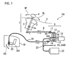
- FIG. 1 is a schematic diagram showing a structure of an automatic transmission with an operating position select device of a preferred first embodiment according to the present invention;
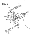
- FIG. 2 is an enlarged perspective view showing an assist actuator that is used in the operating position select device shown in FIG. 1;
- FIG. 3 is an enlarged perspective view showing a mode shift unit with a detent mechanism that is used in the operating position select device shown in FIG. 1;
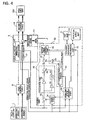
- FIG. 4 is a control bock diagram of a control unit and its peripheral equipment that are used in the operating position select device shown in FIG. 1;
- FIG. 5 is a flowchart of an assist process including an excessive movement preventing process executed in the control unit for controlling the assist actuator during select operation;
- FIG. 6 is a flowchart of the excessive movement preventing process executed at step S10 in the flowchart shown in FIG. 5;
- FIG. 7 is a schematic diagram showing relationships of reaction force acting on a select lever, target reaction force, feedforward assist force, and a cam profile of a detent mechanism with respect to an operating angle when the select lever is shifted from P position to R position; and
- FIG. 8 is a schematic diagram showing relationships of a movement of a detent pin pressed on the cam of the detent mechanism, operating velocity of the select lever, and target assist torque with respect to select position signals when the select lever is shifted from the P position to the R position.
- Throughout the following detailed description, similar reference characters and numbers refer to similar elements in all figures of the drawings, and their descriptions are omitted for eliminating duplication.
- An operating position select device of a first preferred embodiment according to the present invention will be described with reference to the accompanying drawings.
- Referring to FIG. 1 of the drawing, there is shown an
automatic transmission 19 and an operating positionselect device 100 to control thetransmission 19. - The
automatic transmission 19 is a conventional multi-speed transmission with a plurality of planetary gear sets, not shown, and operated among a plurality of operation modes, for example, a parking mode, a reverse drive mode, a neutral mode, a forward drive mode, and a forward low gear drive mode. - The
automatic transmission 19 is provided with the operating positionselect device 100, which shifts the operation modes to a desirable operation mode by manually selecting aselect lever 2 of theselect device 100. - The operating position
select device 100 includes aselect lever unit 1 manually operated by a driver, anoperating angle sensor 200 for detecting an operating angle of theselect lever 2, amode shift unit 300 mounted on theautomatic transmission 19, a first and asecond control cable select lever 2 to themode shift unit 300, anassist actuator 9 for assisting operating force inputted to theselect lever 2 by the driver, anoperating torque sensor 21 for detecting operating force applied to theselect lever 2, and acontrol unit 22 for controlling theassist actuator 9. - The
select lever unit 1 is arranged, for example, at acenter console 3 beside a driver's seat and has theselect lever 2 operated by the driver, abracket 5 fixed to a vehicle body, a supportingshaft 5a fixed on thebracket 5 so as to swingably support theselect lever 2, a knob 4 that is mounted on the top of theselect lever 2 so as to be held by a hand of the driver, and a checking mechanism, not shown, for ensuring theselect lever 2 to be kept in a selected mode position. - The
select lever 2 is set to be about 100 mm in length in this embodiment, which is shorter by about 250 mm than a conventional type select lever. Thelever 2 is operatable by the driver swingably in a first direction toward a P position as indicated by an arrow BP and a second direction, opposite to the first direction, toward a L position as indicated by an arrow BL. - The
select lever 2 can be positioned in one of select positions: the P position corresponding to the parking mode of theautomatic transmission 19, an R position corresponding to the reverse drive mode, an N position corresponding to the neutral mode, a D position corresponding to the forward drive mode, and the L position corresponding to the forward low geared drive mode. - The
assist actuator 9, as shown in FIGS. 1 and 2, includes anelectric motor 15 with reduction gears reducing rotation speed of an output shaft of themotor 15, aworm 16 that is formed on the outer peripheral surface of the output shaft, and aworm wheel 14 that is in mesh with theworm 16 and integrally united to thecoupling shaft 12 coupling the first andsecond control cables - The
worm wheel 14 is provided on its upper surface with an electric terminal 24 contacting to a carbon resistor 25, indicated by a dashed line in FIG. 2, that is printed on a substrate fixed to a case of theassist actuator 9. The electric terminal 24 and the carbon resistor 25 constitute theoperating angle sensor 200 for detecting an operating angle of theselect lever 2 to output an operating angle signal to thecontrol unit 22. - The electric terminal 24 is movable together with and around the
coupling shaft 12 to change its position with respect to the carbon resistor 25 that is immobile and detects a rotating angle of thecoupling shaft 12 for outputting the operating angle signal. The operating angle signal is, for example, proportional to the operating angle of theselect lever 2, both of which increase as theselect lever 2 moves toward the L position, in the second direction BL. Theoperating angle sensor 200 corresponds to an operating position sensor of the present invention, and the operating angle signal corresponds to an operating position signal of the present invention. - There is provided a
torque sensor 21 attached to thecoupling shaft 12 so as to detect the operating force applied to theselect lever 2, which is proportional to operating torque applied to thecoupling shaft 12. Thetorque sensor 21 detects the operating force based on relative torsion between the upper and lower portions of thecoupling shaft 12 and outputs an operating force signal to thecontrol unit 22. The operating force signal, for example, increases with the operating force applied to theselect lever 2. Thetorque sensor 21 corresponds to an operating force sensor of the present invention. - The
mode shift unit 300 shifts the operation modes of theautomatic transmission 19 according to an operated position of theselect lever 2. Referring to FIGS. 1 and 3 of the drawings, themode shift unit 300 has amanual plate lever 20 and adetent mechanism 350 for keeping themanual plate lever 20 in a position selected by theselect lever 2. - The
manual plate lever 20 is integrally fixed in its intermediate portion with arotary shaft 26, and connected at its one end portion with thesecond control cable 18 so as to be rotated on theshaft 26 with respect to a case of thetransmission 19 according to select operation of theselect lever 2. Therotary shaft 26 is fixed to adetent plate 27 of thedetent mechanism 350. - The
detent mechanism 350 includes thedetent plate 27 with acam 270, adetent pin 29 to be pressed onto thecam 270, and aspring plate 28 acting its spring force on thedetent pin 29. - The
detent plate 27 is mechanically connected with avalve spool 310 of a manual valve disposed in acontrol valve unit 400 of theautomatic transmission 19 so as to move thespool 300 according to a select position. Thedetent plate 27 is formed on its upper portion with thecam 270 havingtop portions 27a andbottom portions 27b. Eachbottom portion 27b is arranged between the adjacenttop portions 27a and corresponds with one of the five operation modes of theautomatic transmission 19. - The
cam 270 is pressed by thedetent pin 29 that is urged by thespring plate 28. Thespring plate 28 is mounted at its one end portion on thecontrol valve unit 400 and supports thedetent pin 29 at its other end portion. Thespring plate 28 presses thedetent pin 29 onto thecam 270 of thedetent plate 27 so that thedetent pin 29 is positioned in one of thebottom portions 27b to detain thevalve spool 310 of the manual valve in the selected position. - The
detent plate 27 is coupled at its cam side portion with aparking rod 30 having awedge 30a that can press aparking pawl 31. Thewedge 30a is movable along therod 30 and presses theparking pawl 31 by spring force of acoil spring 30b so that thepawl 31 engages with aparking wheel 32 united to an output shaft of theautomatic transmission 19 when theselect lever 2 is shifted to the P position. This engagement of thepawl 31 and thewheel 32 results in locking drive wheels, not shown, for parking a motor vehicle. - The
mode shift unit 300 is mechanically connected with theselect lever 2 through the first andsecond control cables first control cable 8 connects at its one end portion with a bottom portion of theselect lever 2 through a first joint 7 and at the other end portion with one end portion of aninput lever 10 through a second joint 11. The other end portion of theinput lever 10 is connected with a top portion of acoupling shaft 12, whose bottom portion is connected with one end portion of anoutput lever 13. The other end portion of theoutput lever 13 is connected with one end portion of thesecond control cable 18 through a third joint 17. The other end portion of thesecond control cable 18 is, as shown in FIGS. 1 and 3, connected with themanual plate lever 20. - The first and
second control cables third joints output plates coupling shaft 12 corresponds to a mechanically connecting means of the present invention. - The
control unit 22 is electrically connected to a power supply PS, ground GND, theoperating angle sensor 200, and thetorque sensor 21. Thecontrol unit 22 receives the operating angle signal from theoperating angle sensor 200 and the operating force signal from thetorque sensor 21 to compute target assist current based on these signals, and drives theelectric motor 15 under pulse width modulation (PWM) control based on the target assist current. - FIG. 4 shows a control block diagram of the
control unit 22 and its related units. When theselect lever 2 is shifted by a driver, theselect lever 2 moves and changes its operating angle, and operating force applied to thelever 2 by the driver is transmitted to themode shift unit 300 through the first andsecond control cables coupling shaft 12. - The
first control cable 8 rotates thecoupling shaft 12, so that the terminal 24 on theworm wheel 14 united with theshaft 12 moves with respect to the carbon resistance 25 to change a relative angle between them. This relative angle, corresponding to an operating angle of theselect lever 2, is detected by theoperating angle sensor 200, which outputs an operating angle signal to thecontrol unit 22. - Operating force applied to the
select lever 2 is transmitted through thefirst control cable 8 to thecoupling shaft 12 and twists it, so that torsion occurs between the upper and lower portions of theshaft 12. This torsion, corresponding to operating force applied to theselect lever 2, is detected by thetorque sensor 21, which outputs an operating force signal to thecontrol unit 22. - The
control unit 22 has an operatingstate judgment part 33 that judges a states of theselect lever 2, an excessive movement prevention part (hereinafter referred to as "EMP") controlpart 50 that prevents theselect lever 2 from passing over a desired select position, a motordrive control part 45 that controls electric current to be supplied to theelectric motor 15 of theassist actuator 9, a feedback (inafter referred to as "FB") controlpart 36, and a feedforward (herein after referred to as "FF") controlpart 42. - The operating
state judgment part 33 calculates the operating angle of theselect lever 2 based on the operating angle signal outputted from theoperating angle sensor 200 and obtains operating velocity and acceleration of theselect lever 2 by computing differential of the operating angle and the operating velocity, respectively. Then, thejudgment part 33 judges an operating start-up and an operating direction of theselect lever 2 based on the operating angle, the operating velocity, and the operating force outputted from thetorque sensor 21 and outputs a judgment result to theFF control part 42, a target table 34, and theEMP control part 50. Thisjudgment part 33 corresponds to an operating velocity detector of the present invention. - The
FF control part 42 has FF compensation tables 43 and amultiplier 44. The FF compensation tables 43 determines FF current based on the operating angle, the operating velocity, and the operating acceleration and outputs an FF current signal to themultiplier 44, where multiplies the FF current signal by FF gain to output the multiplied FF assist current signal to athird adder 41. - The target table 34 receives the operating angle signal from the
operating angle sensor 200 and an operating direction signal from the operatingstate judgment part 33 to determine target reaction force based on them. Then, the target table 34 outputs this target reaction force signal to afirst adder 35. The target table 34 contains data on target reaction forces with respect to operating angles and directions. - The
first adder 35 computes a difference between the detected operating force and the target reaction force by subtracting the target reaction force signal from the operating force signal and outputs its difference signal to theFB control part 36. - The
FB control part 36 includes afirst multiplier 37, asecond adder 38, asecond multiplier 39, and anintegral element 40. Thefirst multiplier 37 computes first proportional current by multiplying the difference signal by proportional gain and outputs a first proportional current signal to thesecond adder 38. Thesecond multiplier 39 computes a second proportional current by multiplying the difference signal by an integral gain and outputs a second proportional signal to theintegral element 40. Theintegral element 40 obtains integral current by calculating integration of the second proportional signal and outputs its integral current signal to thesecond adder 38. Thesecond adder 38 adds the integral current signal to the first current signal and outputs an FB assist current signal to the motordrive control part 45. - The
third adder 41 adds the FF assist current signal outputted from theFF control part 42 to the FB assist current signal outputted from theFB control part 36 and outputs a motor assist current signal to the motordrive control part 45. - The
EMP control part 50 receives the operating angle signal from theoperating angle sensor 200, the operating velocity signal from the operatingstate judgment part 33, and an operating reaction force signal outputted from areaction force map 52 to refer to an excessive movement velocity (hereinafter referred to as "EMV")map 51 and obtains a velocity threshold that thereaction force map 52 determines based on the operating angle and velocity and the operating reaction force. Thecontrol part 50 judges whether or not the operating velocity detected is larger than the velocity threshold. An EMP signal is outputted from thecontrol part 50 so as to reduce motor assist current when the judgment result is YES to the motordrive control part 45. - The
EMV map 51 has data on velocity thresholds with respect to the operating angles, the operating velocities, and the operating reaction forces. The velocity threshold corresponds to a maximum velocity at which the select lever is estimated to halt within an oncoming select position based on at least one of the operating velocity and an operating force applied to the select lever. Accordingly, theselect lever 2 does not pass over the oncoming select position when the operating velocity of thelever 2 is smaller than the velocity threshold. - The
reaction force map 52 has data on a characteristic of operating reaction force with reference to the operating angle of theselect lever 2, for example, shown in FIG. 7. This data is rewritten based on at least one of the operating force, the operating angle, the operating velocity, and the target assist force at anytime. The target assist force is determined according to the motor assist current signal. When the data of thereaction force map 52 is rewritten, the excessivemovement velocity map 51 is rewritten. - The motor
drive control part 45 receives the motor assist current signal from thethird adder 41 and the IHP signal from theIHP control part 50 and outputs motor drive current determined based on these signals to theelectric motor 15 under Power Width Modulation (PWM) control. In stead of the PMW control, themotor 15 may be driven under other controls, such as current control or armature voltage control. - The
motor 15 applied motor torque to thecoupling shaft 12 so as to obtain resultant force by adding its assist force to the operating force in the select operation, so that the resultant force moves the first andsecond control cables select lever 2, and themode shift unit 300 to shift the operation modes of theautomatic transmission 19. - In the
select device 100, when the operating positionselect unit 100 fails electrically because of a broken electric wire for example, the operating force of theselect lever 2 is directly transmitted from thelever 2 to themode shift unit 300 mechanically through the first andsecond control cables output levers mode shift unit 300 to shift the modes of theautomatic transmission 19 although its operating force becomes larger than in a normal state. - FIG. 5 shows a flowchart of an assist process executed in the
control unit 22 to control the assistactuator 9 when theselect lever 2 is operated by the driver. - At step S1, the
control unit 22 receives an operating force signal from thetorque sensor 21 to read operating force F applied to theselect lever 2, and then the flow goes to step S2. - At the step S2, the
control unit 22 receives an operating angle signal from theoperating angle sensor 200 to read an operating angle AOP of theselect lever 2, and then the flow goes to step S3. - At the step S3, the operating
state judgment part 33 calculates an operating direction DOP of theselect lever 2 based on a difference between the operating angle signals that are read control-periodically from theoperating angle sensor 200, and then the flow goes to step 4. - At the step S4, the
judgment part 33 computes operating velocity VOP and operating acceleration αOP based on the operating angle signals AOP that are read control-periodically from theoperating angle sensor 200, and then the flow goes to step S5. - At the step S5, the
FF control part 42 refers to the FF compensation tables 43 to select an optimum one from the tables 43 based on the operating angle AOP, the operating velocity VOP, and the operating acceleration αOP, and then the flow goes to step S6. - At the step S6, the operating
state judgment part 33 refers to the target table 34 to obtain target reaction force, and then the flow goes to step S7. - At the step S7, the
FF control part 42 sets FF assist force Fff by using the optimum table and outputs it to thethird adder 41, and then the flow goes to step S8. - At the step S8, the
FB control part 36 sets FB assist force Ffb based on the target reaction force and outputs it to thethird adder 41, and then the flow goes to step S9. - At the step S9, the
third adder 41 obtains target assist force Fa by adding the FF assist force Fff to the FB assist force Ffb and outputs the target assist force Fa to the motordrive control part 45, and then the flow goes to step S10. - At the step S10, the excessive
movement prevention part 50 executes an excessive movement preventing process, and then the flow goes to step S11. The excessive movement preventing process will be described in detail later. - At the step S11, the motor
drive control part 45 outputs motor drive current controlled under PWM control to theelectric motor 15, and the flow ends. - FIG. 6 shows a flowchart of the excessive movement preventing process executed at the step S10 in the flowchart shown in FIG. 5.
- At step S 101, the excessive
movement prevention part 50 refers to the excessivemovement velocity map 51, and then the flow goes to step S102. - At the step S102, a velocity threshold VLM is set based on the operating angle AOP, and then the flow goes to step S103.
- At the step S103, the
prevention part 50 judges whether or not the operating velocity VOP obtained from the operatingstate judgment 33 is larger than the velocity threshold VLM. If YES, the flow goes to step S104, while, if NO, the flow goes to RETURN. - At the step S104, subtraction force FMN is set based on the exceeding amount of the operating velocity VOP that is determined from a difference between the operating velocity VOP detected and the velocity threshold VLM, and then the flow goes to step S105.
- At the step S105, the target assist force FTA is determined by subtracting the subtraction force FMN from temporary target assist force FTA obtained from the
third adder 41, and the flow goes to RETURN. - FIG. 7 shows characteristic relationships of the reaction force Fm, the target reaction force Ft, the FF assist force Fff, and a cam profile with respect to the operating angle AOP, respectively, during the select operation from the P position to the R position.
- The reaction force Fm acting on the knob 4 of the
select lever 2 is obtained from the computation using select torque detected by thetorque sensor 21 when themotor 15 is not driven in the select operation shifted from the Position to the R position. The reaction force Fm is generated by resultant force from the sum of friction force caused by the first andsecond cables motor 15, spring force of thedetent mechanism 350 and others. This reaction force Fm increases in a direction opposite to the operating direction of thelever 2 with the operating angle AOP to have its peak portion Fma before thedetent pin 29 gets over thetop portion 27a of thecam 270, and then decreases with increasing the angle AOP. - After the
pin 29 passes over thetop portion 27a, the reaction force Fm acts on theselect lever 2 in the operating direction so as to move it to thebottom portion 27b of the R position because thespring plate 28 applies its spring force through thedetent pin 29 to thecam 270 to rotate, with pulling theselect lever 2 into thebottom portion 27b of the R position. This denotes that the operating force applied to theselect lever 2 needs to be larger than the reaction force Fm in order to manually move theselect lever 2 for the select operation when themotor 15 is not driven. - The target reaction force Ft, which is set based on the operating angle AOP so as to obtain high select operating performance. The target reaction force Ft is determined according to the reaction force Fm. Note that a peak portion Fta of the target reaction force Ft is short of the peak portion Fma of the reaction force Fm in this embodiment.
- The FF assist force Fff is set to be about a half of the reaction force Fm.
- FIG. 8 is a diagram for the explanation of the excessive movement prevention process, and shows relationships of a movement of the
detent pin 29 pressed onto thecam 270 of thedetent mechanism 350, the operating velocity VOP of theselect lever 2, and the target assist torque with respect to select position signals when theselect lever 2 is shifted from the P position to the R position. - In the select operation, the
detent pin 29 moves forward and backward together with the movement of thelever 2, providing thelever 2 with the reaction force in the operating direction or its opposite direction. - The reaction force Fm acts on the
select lever 2 against the operating force until thedetent pin 29 reaches the peak of thecam 270 because thedetent plate 27 united with themanual plate lever 300 is biased by the spring force of thespring plate 28 in a direction opposite to the operating direction. In this operation zone, the operating force for moving theselect lever 2 in the operating direction needs to overcome the reaction force produced by the spring force of thespring plate 28, and thelever 2 moves with increasing the amount of deformation of thespring plate 28. This results in increasing the reaction force acting on thelever 2. - When the
detent pin 29 is on the peak, the reaction force in the operating direction and its opposite direction becomes zero, and thespring plate 28 is deformed to the maximum degree. - After the
detent pin 29 passes over the peak until it reaches the bottom of the cam corresponding to the R position, thespring plate 28 starts to reduce its amount of deformation with applying the spring force to thedetent plate 27, so that thedetent plate 27 is pressed to rotate so that thelever 2 is assisted to move forward. In this operation zone, the reaction force Fm increases in the lever-assisting direction, and then decreases until thedetent pin 29 reaches the bottom of thecam 270 corresponding the R position. - This reversing characteristic of the reaction force causes affects a select feeling and/or an excessive movement of the
select lever 2; the driver can hardly feel the select position and/or he or she moves thelever 2 so that it passes over the desired select position. This excessive movement operation depends heavily on operating velocity of thelever 2; the possibility of the excessive movement increase with the operating velocity. - In order to prevent the excessive movement, the operating position
select device 100 of the embodiment reduces the assist force when the operating velocity VOP is larger than the velocity threshold VLM, thereby preventing thelever 2 to pass over the select position and ensuring its halt in the select position. - This operating position
select device 100 of the first embodiment has many advantages described below. - The
select lever 2 can be shorter than a conventional one by about 150 mm at its portion projecting from a center console toward a passenger compartment without increasing an operating force applied to theselect lever 2 so much. This brings a design freedom concerning an installation location of the select lever and/or a layout of a passenger compartment to be broadened. - When operating the
select lever 2, assist torque from theelectric motor 15 is applied to thecoupling shaft 12 of the mechanically connecting mechanism so as to reduce the operating force applied to theselect lever 2. When the operating positionselect unit 100 fails electrically, a driver can shift themode shift unit 300 by operating theselect lever 2 because theselect lever 2 and themode shift unit 300 are mechanically connected by the mechanically connecting mechanism, such as the first andsecond control cables - The assist control of the
motor 15 are performed by using the FF and FB assist currents, which gives high response to select operation. - The deceasing of the assist force when the operating velocity VOP of the
select lever 2 exceeds the velocity threshold VLM can prevent thelever 2 from its excessive movement, passing over the select position. The lever excessive movement can be prevented despite of the magnitude of the operating velocity because the assist force is decreased with increasing the operating velocity. This excessive movement preventing control can be performed without other additional device, which gives lower manufacturing cost. The EMV map offers a high response to high operating velocity of thelever 2. The rewriting data of thereaction force map 52 keeps ensuring lever excessive preventing control as theselect device 100 is used for a long time. - While there have been particularly shown and described with reference to preferred embodiments thereof, it will be understood that various modifications may be made therein.
- For example, the operating force F may be detected based on an estimate from supply current to the
motor 15 and its rotational speed in stead of using thetorque sensor 21. - The mechanically connecting mechanism may be rods or linkage instead of the first and
second control cables - The select lever may have a configuration different from that of the first embodiment shown in FIG. 1, for example, a finger- controable one.
- The configuration of the cam of the detent mechanism may be formed arbitrarily to have different target reaction force.
- The ratio of the FF assist force Fff to the FB assist force Ffb may be set arbitrarily according to a target operating characteristics.
- The assist force produced by the electric motor may be controlled based on at least the operating angle AOP.
- The subtraction force FMN may be set larger than the temporary target assist force Ft when the operating velocity or the operating force has a large value. In this case, the resultant target assist force Ft acts on the
select lever 2 in the direction opposite to the operating direction of thelever 2. - The operating position can be detected by the displacement amount of the
select lever 2 or the mechanically connectingmechanism 400 that connects theselect lever 2 and themode shift unit 300 with each other instead of the operating angle of theshift lever 2.
Claims (6)
- Operating position select device (100) adapted for an automatic transmission (19) whose operation modes are shiftable, the operating position select device (100) comprising:a select lever unit (1) having a select lever (2) that is operated by a driver between a plurality of select positions corresponding to the operation modes;an operating position sensor (200) that detects an operating position of said select lever (2) and outputs an operating position signal;a mode shift unit (300) mountable on the automatic transmission (19) to shift operation modes of the automatic transmission (19);a mechanically connecting means (8, 18, 12) that mechanically connects said select lever (2) and said mode shift unit (300) with each other;an assist actuator (9) that is arranged between said select lever (2) and said mode shift unit (300) and supplies assist force to said select lever (2);an operating velocity detector (33) that detects operating velocity of said select lever (2); anda control unit (22) that controls said assist actuator (9) based on at least the operating position signal, said control unit (22) having an excessive movement prevention part (50) that prevents the select lever (2) from passing over a desired select position by reducing the assist force when the operating velocity outputted from said operating velocity detector (33) exceeds a velocity threshold.
- Operating position select device (100) according to claim 1,
wherein the excessive movement prevention part (33) decreases the assist force with increasing an excess amount of the operating velocity over the velocity threshold. - Operating position select device (100) according to claim 1 or 2,
wherein the excessive movement prevention part (33) is provided with an excessive movement velocity map (51) that has data on the velocity thresholds determined based on at least the operating position. - Operating position select device (100) according to any one of claim 1 to 3,
wherein the excessive movement prevention part (33) is provided with a reaction force map (52) that has data on reaction force acting on said select lever (2) determined based on at least the operating position. - Operating position select device (100) according to claim 4,
wherein the data of the reaction force map (52) is rewritten based on at least one of the operating position, the operating velocity, an operating force applied to said select lever (2), and the assist force. - Operating position select device (100) according to any one of claim 1 to 5,
wherein the velocity threshold corresponds to a maximum velocity at which said select lever (2) is estimated to halt within an oncoming select position based on at least one of the operating velocity and an operating force applied to said select lever (2).
Applications Claiming Priority (2)
| Application Number | Priority Date | Filing Date | Title |
|---|---|---|---|
| JP2003369415A JP4360176B2 (en) | 2003-07-04 | 2003-10-29 | Select assist device for automatic transmission |
| JP2003369415 | 2003-10-29 |
Publications (2)
| Publication Number | Publication Date |
|---|---|
| EP1528296A1 EP1528296A1 (en) | 2005-05-04 |
| EP1528296B1 true EP1528296B1 (en) | 2007-02-07 |
Family
ID=34420178
Family Applications (1)
| Application Number | Title | Priority Date | Filing Date |
|---|---|---|---|
| EP04292568A Expired - Lifetime EP1528296B1 (en) | 2003-10-29 | 2004-10-29 | Operating position select device for automatic transmission |
Country Status (3)
| Country | Link |
|---|---|
| US (1) | US7367244B2 (en) |
| EP (1) | EP1528296B1 (en) |
| DE (1) | DE602004004617T8 (en) |
Families Citing this family (11)
| Publication number | Priority date | Publication date | Assignee | Title |
|---|---|---|---|---|
| US7194927B2 (en) * | 2003-09-17 | 2007-03-27 | Calsonic Kansei Corporation | Operating position select device for automatic transmission |
| SE0400192L (en) * | 2004-01-30 | 2004-12-14 | Volvo Lastvagnar Ab | Method and device for counteracting inappropriate manual shifting at predetermined vehicle conditions |
| JP4255889B2 (en) * | 2004-07-07 | 2009-04-15 | 日産自動車株式会社 | Assist control method for automatic transmission for vehicle |
| JP2007085411A (en) * | 2005-09-21 | 2007-04-05 | Calsonic Kansei Corp | Select assist device for automatic transmission |
| US7571663B2 (en) * | 2005-10-29 | 2009-08-11 | Harold Vigil | Rotary shifter |
| JP2007336663A (en) * | 2006-06-14 | 2007-12-27 | Denso Corp | Position switching control device |
| JP6173875B2 (en) * | 2013-10-24 | 2017-08-02 | 日立オートモティブシステムズ株式会社 | Automatic transmission range switching device |
| DE102013021235A1 (en) | 2013-12-13 | 2014-07-31 | Daimler Ag | Method for controlling automated vehicle transmission, involves adjusting switching behavior of vehicle transmission in response to operation velocity intended for manual switching operation of electric operating elements |
| WO2016139147A1 (en) * | 2015-03-04 | 2016-09-09 | Abb Ag | Safety control system and method of operation of a safety control system |
| CN105889496A (en) * | 2016-06-21 | 2016-08-24 | 杭州虬龙科技有限公司 | Electronically-controlled limitable push-and-pull device |
| CN114397114B (en) * | 2022-01-06 | 2024-04-09 | 一汽解放汽车有限公司 | Test bench |
Family Cites Families (15)
| Publication number | Priority date | Publication date | Assignee | Title |
|---|---|---|---|---|
| US5537885A (en) | 1994-08-04 | 1996-07-23 | Thomas; Gerald A. | Electronically controlled gear shift mechanism particularly suited for racing cars |
| US5758543A (en) * | 1996-05-06 | 1998-06-02 | Eaton Corporation | Shift lever assembly for minimizing jumpout |
| JPH09323559A (en) | 1996-06-05 | 1997-12-16 | Nissan Motor Co Ltd | Operating device for automatic transmission |
| US5868034A (en) * | 1997-04-08 | 1999-02-09 | Mcfadden; Patrick A. | Shifting apparatus for controlling a transmission shifter in a vehicle |
| JP2987121B2 (en) | 1997-04-18 | 1999-12-06 | 京浜精密工業株式会社 | Power shifter control device |
| US5904635A (en) * | 1997-08-07 | 1999-05-18 | Eaton Corporation | Partially automated lever-shifted mechanical transmission system |
| US6067871A (en) | 1997-09-12 | 2000-05-30 | Eaton Corporation | Variable resistance shift rail detent assembly and shift control method employing same |
| US6072390A (en) * | 1999-03-31 | 2000-06-06 | Daimlerchrysler Corporation | Position sensing system for manually operated shift lever of a vehicle transmission |
| FR2796116B1 (en) | 1999-07-08 | 2001-09-07 | Siemens Automotive Sa | CONTROL DEVICE FOR ELECTRICALLY CONTROLLED GEARBOX AND RELATED METHOD |
| US6244127B1 (en) * | 1999-10-28 | 2001-06-12 | Teleflex, Incorporated | Mechanical or electrical transmission shifter |
| US6361473B1 (en) * | 2000-04-27 | 2002-03-26 | Eaton Corporation | System/method for synchronized shifting of a manually shifted transmission |
| DE10051210A1 (en) | 2000-10-16 | 2002-04-25 | Volkswagen Ag | Regulating method for gear selector of motor vehicles with selector shaft movement controlled so that its movement begins before selector finger has reached selected gate |
| JP4183111B2 (en) | 2001-09-27 | 2008-11-19 | ジヤトコ株式会社 | Shift-by-wire system |
| DE602004001880T2 (en) | 2003-01-07 | 2007-04-05 | Calsonic Kansei Corp. | Selector lever for automatic transmission |
| US7231846B2 (en) * | 2004-08-25 | 2007-06-19 | Mack Trucks, Inc. | Magnetic fluid shifter damper mechanism |
-
2004
- 2004-10-28 US US10/974,975 patent/US7367244B2/en not_active Expired - Fee Related
- 2004-10-29 EP EP04292568A patent/EP1528296B1/en not_active Expired - Lifetime
- 2004-10-29 DE DE602004004617T patent/DE602004004617T8/en not_active Expired - Fee Related
Also Published As
| Publication number | Publication date |
|---|---|
| EP1528296A1 (en) | 2005-05-04 |
| DE602004004617T8 (en) | 2008-02-14 |
| US20050139030A1 (en) | 2005-06-30 |
| DE602004004617D1 (en) | 2007-03-22 |
| DE602004004617T2 (en) | 2007-11-08 |
| US7367244B2 (en) | 2008-05-06 |
Similar Documents
| Publication | Publication Date | Title |
|---|---|---|
| US7313980B2 (en) | Operating position select device for automatic transmission | |
| US7367244B2 (en) | Operating position select device for automatic transmission | |
| EP1437533B1 (en) | Select lever for automatic transmission | |
| US7426881B2 (en) | Operating position select device for automatic transmission | |
| EP1517069B1 (en) | Operating position select device for automatic transmission | |
| US20060011003A1 (en) | Operating position select device for automatic transmission | |
| EP1519083A1 (en) | Operating position select device for automatic transmission | |
| US7243567B2 (en) | Operating position select device for automatic transmission | |
| US20050257637A1 (en) | Operating position select device for automatic transmission | |
| US20050247154A1 (en) | Operating position select device for automatic transmission | |
| US20060094565A1 (en) | Operating position select device for automatic transmission | |
| US20070068304A1 (en) | Operating position select device adapted for automatic transmission | |
| EP1355091B1 (en) | A control system for a robotized gearbox in a motor vehicle, with the ability to learn the position of the ratios or gears | |
| JP2955092B2 (en) | Electronically controlled automatic transmission shift device for vehicles | |
| JP2005121037A (en) | Selector assist device for automatic transmission | |
| HK1060169B (en) | A control system for a robotized gearbox in a motor vehicle, with the ability to learn the position of the ratios or gears | |
| JP2005007970A (en) | Select assistant device of automatic transmission | |
| JP2005069441A (en) | Select assist device for automatic transmission | |
| JP2005003085A (en) | Select assist device for automatic transmission | |
| JP2005069443A (en) | Select assist device for automatic transmission |
Legal Events
| Date | Code | Title | Description |
|---|---|---|---|
| PUAI | Public reference made under article 153(3) epc to a published international application that has entered the european phase |
Free format text: ORIGINAL CODE: 0009012 |
|
| AK | Designated contracting states |
Kind code of ref document: A1 Designated state(s): AT BE BG CH CY CZ DE DK EE ES FI FR GB GR HU IE IT LI LU MC NL PL PT RO SE SI SK TR |
|
| AX | Request for extension of the european patent |
Extension state: AL HR LT LV MK |
|
| 17P | Request for examination filed |
Effective date: 20050706 |
|
| AKX | Designation fees paid |
Designated state(s): DE FR GB |
|
| GRAP | Despatch of communication of intention to grant a patent |
Free format text: ORIGINAL CODE: EPIDOSNIGR1 |
|
| GRAS | Grant fee paid |
Free format text: ORIGINAL CODE: EPIDOSNIGR3 |
|
| GRAA | (expected) grant |
Free format text: ORIGINAL CODE: 0009210 |
|
| AK | Designated contracting states |
Kind code of ref document: B1 Designated state(s): DE FR GB |
|
| REG | Reference to a national code |
Ref country code: GB Ref legal event code: FG4D |
|
| REF | Corresponds to: |
Ref document number: 602004004617 Country of ref document: DE Date of ref document: 20070322 Kind code of ref document: P |
|
| ET | Fr: translation filed | ||
| PLBE | No opposition filed within time limit |
Free format text: ORIGINAL CODE: 0009261 |
|
| STAA | Information on the status of an ep patent application or granted ep patent |
Free format text: STATUS: NO OPPOSITION FILED WITHIN TIME LIMIT |
|
| 26N | No opposition filed |
Effective date: 20071108 |
|
| PGFP | Annual fee paid to national office [announced via postgrant information from national office to epo] |
Ref country code: DE Payment date: 20081027 Year of fee payment: 5 |
|
| PGFP | Annual fee paid to national office [announced via postgrant information from national office to epo] |
Ref country code: FR Payment date: 20081014 Year of fee payment: 5 |
|
| PGFP | Annual fee paid to national office [announced via postgrant information from national office to epo] |
Ref country code: GB Payment date: 20081029 Year of fee payment: 5 |
|
| REG | Reference to a national code |
Ref country code: FR Ref legal event code: ST Effective date: 20100630 |
|
| PG25 | Lapsed in a contracting state [announced via postgrant information from national office to epo] |
Ref country code: FR Free format text: LAPSE BECAUSE OF NON-PAYMENT OF DUE FEES Effective date: 20091102 Ref country code: DE Free format text: LAPSE BECAUSE OF NON-PAYMENT OF DUE FEES Effective date: 20100501 |
|
| PG25 | Lapsed in a contracting state [announced via postgrant information from national office to epo] |
Ref country code: GB Free format text: LAPSE BECAUSE OF NON-PAYMENT OF DUE FEES Effective date: 20091029 |