EP1528291A2 - Apparatus and method for filling an automatic transmission with oil - Google Patents
Apparatus and method for filling an automatic transmission with oil Download PDFInfo
- Publication number
- EP1528291A2 EP1528291A2 EP04292470A EP04292470A EP1528291A2 EP 1528291 A2 EP1528291 A2 EP 1528291A2 EP 04292470 A EP04292470 A EP 04292470A EP 04292470 A EP04292470 A EP 04292470A EP 1528291 A2 EP1528291 A2 EP 1528291A2
- Authority
- EP
- European Patent Office
- Prior art keywords
- transmission
- fluid
- torque converter
- further including
- fill
- Prior art date
- Legal status (The legal status is an assumption and is not a legal conclusion. Google has not performed a legal analysis and makes no representation as to the accuracy of the status listed.)
- Granted
Links
Images


Classifications
-
- F—MECHANICAL ENGINEERING; LIGHTING; HEATING; WEAPONS; BLASTING
- F16—ENGINEERING ELEMENTS AND UNITS; GENERAL MEASURES FOR PRODUCING AND MAINTAINING EFFECTIVE FUNCTIONING OF MACHINES OR INSTALLATIONS; THERMAL INSULATION IN GENERAL
- F16H—GEARING
- F16H57/00—General details of gearing
- F16H57/04—Features relating to lubrication or cooling or heating
- F16H57/0408—Exchange, draining or filling of transmission lubricant
-
- F—MECHANICAL ENGINEERING; LIGHTING; HEATING; WEAPONS; BLASTING
- F01—MACHINES OR ENGINES IN GENERAL; ENGINE PLANTS IN GENERAL; STEAM ENGINES
- F01M—LUBRICATING OF MACHINES OR ENGINES IN GENERAL; LUBRICATING INTERNAL COMBUSTION ENGINES; CRANKCASE VENTILATING
- F01M11/00—Component parts, details or accessories, not provided for in, or of interest apart from, groups F01M1/00 - F01M9/00
- F01M11/04—Filling or draining lubricant of or from machines or engines
- F01M11/0458—Lubricant filling and draining
Definitions
- the present invention relates to a method and apparatus to fill an automatic transmission with fluid. More particularly, the present invention relates to a fluid filling process occurring while the torque converter of the transmission is being rotated.
- Another method includes weighing each component of the automatic transmission in a dry state and weighing an assembled automatic transmission which has been properly filled. The difference between the weights correlates to the quantity of fluid to be added. Unfortunately, this method may also be subject to undesirable over-filling or under-filling of the transmission based on component weight variation and model mix complexity.
- Yet another method involves filling the transmission to a predetermined level.
- unknown quantities of air are trapped within the torque converter and other cavities of the automatic transmission. Therefore, the transmission may be over-filled or under-filled depending on the quantity of trapped air.
- the transmission assembly plant it is common practice for the transmission assembly plant to provide the transmission in an under-filled condition to the vehicle assembly plant.
- the transmission is coupled to a transmission cooler and the vehicle's engine. Once these connections have been made, a final fill or "top off' operation is performed to assure that the automatic transmission has been filled to the proper level.
- the top off operation is costly and time consuming.
- the present invention provides a method and apparatus for properly filling a transmission at the transmission assembly plant.
- a method of filling a transmission with fluid including the steps of pumping fluid through the transmission entering at the first port and exiting through the second port, rotating the torque converter to purge trapped air, shifting the transmission, filling the transmission to a desired level and plugging the first and second ports.
- the transmission is placed in a "road ready" condition and will not require additional fluid to be added in a top off operation at the vehicle assembly plant.
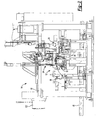
- an exemplary automatic transmission 10 is positioned within an oil fill machine 12 constructed in accordance with the teachings of the present invention.
- Oil fill machine 12 is depicted as a work station 14 positioned along a conveyor 16 of an automatic transmission assembly line.
- Oil fill machine 12 is configured to allow transmissions to sequentially enter work station 14, be filled with fluid and exit the work station once the fill process of the present invention has been completed.
- Work station 14 includes a gantry frame 18 supporting overhead tooling including a fill nozzle 20, a shifter collet 22, a temperature compensation tool 24 and a dipstick plug tool 26.
- a drive unit 28, a return nozzle 30, and a cooler fitting tool 32 are also positioned within work station 14 and may be coupled to gantry frame 18.
- oil fill machine 12 functions to accurately fill automatic transmission 10 with fluid such that a subsequent top off filling operation is not required at the vehicle assembly plant.
- drive unit 28 rotates a torque converter 34 of transmission 10 while fluid is pumped through the automatic transmission.
- fluid is stored in a tank 36 having a motor 38 and a pump 40 coupled thereto. Fluid may be selectively dispensed through fill nozzle 20 by opening a combination of three inlet valves.
- a fast fill valve 42 provides substantially unrestricted flow from pump 40 to nozzle 20.
- a slow fill valve 44 is plumbed in series with an orifice 46. Orifice 46 reduces the flow through fill nozzle 20 and allows for more accurate control of the final fill level as will be described in greater detail hereinafter.
- a nozzle valve 47 is located within fill nozzle 20. Nozzle valve 47 receives fluid allowed to pass by fast fill valve 42 and/or slow fill valve 44.
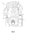
- automatic transmission 10 includes a housing 48 having a dipstick aperture 50, a temperature compensation aperture 52, a cooler fitting aperture 54 and a shifter aperture 56.
- drive unit 28 is operable to selectively engage torque converter 34 and rotate the torque converter during filling.
- fill nozzle 20 enters dipstick aperture 50 and return nozzle 30 enters cooler fitting aperture 54 to define the path of fluid flow during the filling operation.
- Station and tank exit valves 58 and 59, respectively, are plumbed in line between return nozzle 30 and tank 36 to selectively restrict the flow through transmission 10.
- Drive unit 28 includes a spindle 60 having a plurality of drive lugs 62 axially extending therefrom.
- a vacuum cup 64 is fixed to spindle 60.
- Vacuum cup 64 includes an outer lip 66 for selective engagement with torque converter 34.
- An aperture 68 extends through vacuum cup 64 and is in communication with a vacuum source (not shown).
- Spindle 60 is rotatably mounted to a support 70.
- Support 70, as well as spindle 60, are axially moveable along a slide 72 to provide a method for selectively engaging drive lugs 62 and vacuum cup 64 with torque converter 34.
- pallet 74 enters work station 14.
- pallet clamps 76 engage pallet 74 to fix the position of transmission 10 with oil fill machine 12.
- cooler fitting tool 32 advances toward a bank of cooler fittings. One cooler fitting is fed toward and coupled to cooler fitting tool 32.
- drive unit 28 is advanced to engage drive lugs 62 with torque converter 34.
- Outer lip 66 of vacuum cup 64 also engages torque converter 34.
- fill nozzle 20 is advanced to engage dipstick aperture 50.
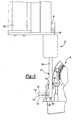
- fill nozzle 20 includes a supply tube 105 and a depth gage 106.
- Depth gage 106 includes a bubbler transducer which measures the pressure head generated at an end face 108 of depth gage 106.
- the bubbler transducer is calibrated to provide a signal equivalent to fluid depth in millimeters.
- end face 108 is inserted a predetermined distance from a land 110 of transmission housing 48. As such, end face 108 defines a plane 112 from which fluid depth measurements are taken.
- Line 114 represents 15 mm of fluid depth.
- Line 116 represents 19 mm of fluid depth and line 118 represents 30 mm of fluid depth above end face 108.
- Fast fill valve 42, slow fill valve 44, nozzle valve 47, station exit valve 58, tank exit valve 59 and depth gage 106 are in communication with a controller 121. Controller 121 actuates the fill valves and the exit valves based on feedback provided by depth gage 106 to maintain a desired fluid level.
- actuator 122 is mounted to gantry frame 18 and is controllable to selectively raise and lower slide 120 and fill nozzle 20.
- actuator 122 may include any number of mechanical operators such as electric motors, hydraulic pistons, gear transfer mechanisms, chain drive mechanisms and the like.
- Actuator 122 may also be coupled to a positioning mechanism (not shown) to move actuator 122 within the space defined by gantry frame 18.
- Step 104 also includes advancing temperature compensation tool 24 as shown in Figure 6.
- Temperature compensation tool 24 includes a 12-pin receptacle 124 coupled to a slide 126 operable to raise and lower 12-pin receptacle 124 in to and out of communication with a 12-pin connector 128.
- 12-pin connector 128 was mounted within transmission 10 prior to the transmission's arrival within work station 14.
- 12-pin connector 128 is in communication with a thermocouple mounted within transmission housing 48.
- temperature compensation tool 24 operates to communicate a signal indicative of the fluid temperature to controller 121 to provide the controller with fluid temperature data during the filling operation. Because the density of the fluid used in the automatic transmission changes with temperature, monitoring of the fluid temperature during filling improves fill accuracy. Controller 121 adjusts the final fill height to account for the volumetric change due to changes in temperature.
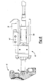
- shifter collet 22 is advanced as shown in Figure 7.
- Shifter collet 22 includes a sleeve 134 which is selectively engageable with a shifter shaft 136. Rotation of shifter shaft 136 causes transmission 10 to shift through the available gear ratios.
- An encoder 137 communicates the rotational position of sleeve 134 to controller 121.
- Shifter collet 22 includes a slide 138 coupled to gantry frame 18 for raising and lowering shifter collet 22 in to and out of engagement with shifter shaft 136.
- Shifter collet 22 also includes an actuator 140 for incrementally rotating shifter shaft 136. It is contemplated that shifter collet 22 may be moved from side to side within gantry frame 18 as well as in a vertical manner as previously described.
- transmission 10 is shifted into park.
- step 144 vacuum is supplied through aperture 68 to axially displace torque converter 34 toward drive unit 28. This operation properly positions torque converter 34 relative to the internal fluid passageways within automatic transmission 10.
- return nozzle 30 is advanced into engagement with cooler fitting aperture 54 as shown in Figure 8. At this time, a complete fluid circuit from tank 36 through fill nozzle 20, automatic transmission 10, return nozzle 30 and back to tank 36 is defined.
- Return nozzle 30 includes station exit valve 58 and a pressure transducer 147. Pressure transducer 147 provides a signal indicative of the fluid pressure exiting the transmission through return nozzle 30.
- Return nozzle 30 is mounted to a slide 149 which allows the return nozzle to move between the advanced position engaged with cooler fitting aperture 54 and a retracted position disengaged from the transmission.
- a retaining arm restricting rotation of torque converter 34 is disengaged to allow the torque converter to rotate.
- nozzle valve 47, fast fill valve 42 and slow fill valve 44 are opened.
- Step 152 defines filling the transmission to a depth of 15 mm represented by line 114 in Figure 5. Once the 15 mm depth has been met, station exit valve 58 is opened at step 154 to allow fluid to flow through transmission 10.
- Tank exit valve 59 remains closed to create a back pressure within transmission 10.
- Fast fill valve 42, slow fill valve 44 and nozzle valve 47 are controlled to assure that a depth of at least 15 mm is maintained throughout the remaining steps.
- drive unit 28 causes torque converter 34 to begin to rotate.
- Drive unit 28 maintains the torque converter speed at a predetermined value such as 1800 rpm.
- the 15 mm depth corresponds to a minimum sump level which is maintained to assure that additional air is not pumped into the system.
- shifter collet 22 rotates shifter shaft 136 to cause the transmission to shift gears.
- the transmission will be operated for two seconds in each of the available gears including park, reverse, neutral, drive and any ancillary gear settings.
- each of the hydraulic servos associated with the internal clutches of the transmission are actuated to fill their respective servo chambers.
- Torque converter rotation is stopped at step 160.
- the torque converter is stopped to allow the transmission to be shifted into park at step 162.
- drive unit 28 rotates torque converter 34 at 1800 rpm as depicted in step 164.
- Pressure transducer 147 provides a signal indicative of the fluid pressure exiting the transmission. Once pressure transducer 147 indicates that a pressure of 20 psig has been reached, tank exit valve 59 is opened at step 166. Next, the transmission is purged of air as depicted at step 170. During the purging cycle, station and tank exit valves 58 and 59 as well as fast fill valve 42, slow fill valve 44 and nozzle valve 47 are controlled to maintain a fluid depth of 30 mm.
- fast fill valve 42 and slow fill valve 44 are closed at step 172.
- fluid is allowed to drain into tank 36. Once the fluid level has been below the 19 mm line for one second, station and tank exit valves 58 and 59 are closed at step 176.
- slow fill valve 44 is opened to begin the final filling portion of the process.
- Line 116 is offset a distance of 19 mm from end face 108 of depth gage 106.
- the 19 mm line represents a nominal target fill level. This target fill level incorporates an excess volume of fluid which will fill the lines interconnecting transmission 10 and the transmission fluid cooler mounted on the vehicle.
- the 19 mm line is a nominal target that controller 121 uses as a starting point to determine the final fill depth. Based on the temperature/viscosity curve of the fluid and the fluid temperature as relayed by temperature compensation tool 24, an adjusted final fill depth is calculated at step 180.
- step 182 fluid is allowed to pass through slow fill valve 44 and orifice 46 until the adjusted fill level is met.
- slow fill valve 44 is closed.
- drive unit 28 is instructed to stop rotating torque converter 34. Once torque converter 34 has stopped rotating, shifter collet 22 shifts the transmission into the vehicle assembler's desired gear position at step 188. For example, some manufacturers wish to have the transmission placed in neutral while others desire to have the transmission placed in park prior to assembly within the vehicle.
- step 190 fill nozzle 20 and return nozzle 30 are retracted away from the transmission.
- step 192 dipstick plug tool 26 advances and inserts the dipstick plug.
- step 194 cooler fitting tool 32 advances and installs a cooler fitting plug.
- dipstick plug tool 26 and cooler fitting tool 32 retract away from transmission 10.
- step 196 the retaining arm which was previously disengaged from the torque converter is now allowed to engage the torque converter.
- vacuum is no longer supplied through aperture 68 and lip 66 is disengaged from torque converter 34.
- step 200 support 70 and spindle 60 are retracted along slide 72 to disengage lugs 62 from torque converter 34.
- Pallet clamps 76 disengage pallet 74 at step 202.
- Pallet 74 and automatic transmission 10 exit oil fill machine 12 and work station 14.
- the temperature compensation tool and the fill nozzle may be mounted on a singular slide and moved by a single actuator.
- the amount of fluid present within the automatic transmission may be determined by any number of devices including sight gages, dipsticks, capillary tubes and the like, without departing from the scope of the present invention.
Landscapes
- Engineering & Computer Science (AREA)
- General Engineering & Computer Science (AREA)
- Mechanical Engineering (AREA)
- Loading And Unloading Of Fuel Tanks Or Ships (AREA)
- General Details Of Gearings (AREA)
- Valves And Accessory Devices For Braking Systems (AREA)
- Automatic Assembly (AREA)
Abstract
Description
- Figure 1 is a schematic view of an exemplary work station including the oil fill machine of the present invention;
- Figure 2 is a side view of the work station including an exemplary transmission;
- Figure 3 is a perspective view of an exemplary automatic transmission;
- Figure 4 is a flow chart depicting the process of filling an automatic transmission;
- Figure 5 is a fragmentary cross-sectional side view depicting a fill nozzle and an automatic transmission;
- Figure 6 is a fragmentary cross-sectional side view depicting a temperature compensation tool in conjunction with an automatic transmission;
- Figure 7 is a fragmentary cross-sectional side view depicting a shifter collet in conjunction with an automatic transmission; and
- Figure 8 is a cross-sectional side view depicting a return nozzle in conjunction with an automatic transmission.
Claims (29)
- A fluid fill machine for an automatic transmission having a torque converter, a first port and a second port, the fill machine comprising:a pressurized fluid source;an inlet nozzle in communication with said fluid source and adapted to be coupled to the first port;an outlet nozzle adapted to be coupled to the second port;a drive motor adapted to selectively engage and rotate the torque converter;a fluid depth gage that generates a fluid depth signal; anda controller that controls said drive motor to rotate the torque converter to purge the transmission of air, said controller operable to vary the flow of fluid through said inlet and outlet nozzles to fill the transmission to a desired fluid depth based on said fluid depth signal.
- The fill machine of claim 1 further including a motor, a pump and a tank, said motor drivingly coupled to said pump, said pump supplying fluid to said inlet nozzle.
- The fill machine of claim 2 further including a gantry frame supporting said inlet nozzle.
- The fill machine of claim 3 further including an actuator coupled to said inlet nozzle, said actuator being adapted to move said inlet nozzle into contact with said transmission.
- The fill machine of claim 1 wherein said depth gage includes a pressure transducer to determine a depth of fluid.
- The fill machine of claim 1 further including a torque converter positioning device.
- The fill machine of claim 6 wherein said torque converter positioning device includes a vacuum cup adapted to axially position the torque converter relative to a transmission housing.
- The fill machine of claim 1 further including a shifting tool adapted to engage the transmission and vary the gear ratio produced by the transmission.
- The fill machine of claim 8 wherein said shifting tool includes a spindle coupled to an actuator for rotating said spindle.
- The fill machine of claim 1 further including a cooler plug slide adapted to install a cooler plug on the transmission.
- The fill machine of claim 1 further including a first valve and a second valve plumbed in parallel paths interconnecting said fluid source and said inlet nozzle, said first valve operable to selectively supply fluid at a predetermined flow rate to said inlet nozzle, said second valve operable to selectively supply fluid at a reduced flow rate to said inlet nozzle.
- A method for filling an automatic transmission with fluid, the transmission having a first fluid port, a second fluid port and a torque converter, the method comprising the steps of:pumping fluid through the transmission entering at the first port and exiting through the second port;rotating the torque converter to purge trapped air;shifting the transmission;filling the transmission to a desired level; andplugging the first and second ports.
- The method of claim 12 further including pumping the fluid into the transmission until a predetermined level is reached prior to rotating the torque converter.
- The method of claim 13 further including maintaining at least said predetermined fluid level during the rotating step.
- The method of claim 14 wherein shifting the transmission includes operating the transmission in each of the transmission drive ratios.
- The method of claim 15 further including filling the transmission at a first rate until a predetermined level is reached, allowing some fluid to drain out of the transmission and filling the transmission at a second rate slower than said first rate after some of the fluid is allowed to drain.
- The method of claim 12 further including stopping the torque converter and shifting the transmission into park.
- The method of claim 17 further including restricting flow through said second port to limit the exit of the fluid.
- The method of claim 18 further including rotating the torque converter and opening the second port to allow the fluid to exit from the transmission after a predetermined fluid pressure is met.
- The method of claim 12 further including overfilling the transmission, purging air out of the transmission during the overfilled condition and draining excess fluid out of the transmission.
- The method of claim 20 wherein the step of draining excess fluid includes reducing flow through the first port to lower the fluid level below a desired fill level and subsequently opening the first port to fill the transmission to the desired fill level.
- The method of claim 12 further including determining the temperature of the fluid and adjusting said desired level to account for fluid changes based on the temperature of the fluid.
- The method of claim 12 further including engaging a tool with the transmission to allow control of the transmission gearing.
- The method of claim 12 further including positioning the torque converter at a desired axial location.
- The method of claim 24 wherein the step of positioning the torque converter includes applying a vacuum to the torque converter.
- The method of claim 12 wherein the rate of fluid entering the transmission is greater than the rate of fluid exiting the transmission.
- A method for filling an automatic transmission with fluid, the transmission having a housing and a torque converter rotatably mounted in the housing, the transmission operable to provide multiple drive ratios, the method comprising:filling the housing with fluid to a predetermined level;rotating the torque converter;shifting the transmission to produce a different drive ratio;stopping the torque converter;shifting the transmission into park;rotating the torque converter;pumping fluid through the housing once a predetermined fluid pressure is met;overfilling the transmission with fluid;purging air from the transmission;draining the housing to a level below a desired final fill level; andfilling the housing to said desired fill level.
- The method of claim 27 further including substantially continuously monitoring a fluid level in the transmission, providing a signal indicative of said fluid level to a controller, said controller varying fluid flow through the housing to maintain desired fluid levels.
- The method of claim 28 further including mounting the transmission to a pallet and temporarily positioning said pallet within a work station having a conveyor extending therethrough.
Applications Claiming Priority (2)
| Application Number | Priority Date | Filing Date | Title |
|---|---|---|---|
| US10/694,633 US7207418B2 (en) | 2003-10-27 | 2003-10-27 | Oil fill machine |
| US694633 | 2003-10-27 |
Publications (3)
| Publication Number | Publication Date |
|---|---|
| EP1528291A2 true EP1528291A2 (en) | 2005-05-04 |
| EP1528291A3 EP1528291A3 (en) | 2006-03-08 |
| EP1528291B1 EP1528291B1 (en) | 2008-03-05 |
Family
ID=34423341
Family Applications (1)
| Application Number | Title | Priority Date | Filing Date |
|---|---|---|---|
| EP04292470A Expired - Lifetime EP1528291B1 (en) | 2003-10-27 | 2004-10-18 | Apparatus and method for filling an automatic transmission with oil |
Country Status (5)
| Country | Link |
|---|---|
| US (1) | US7207418B2 (en) |
| EP (1) | EP1528291B1 (en) |
| AT (1) | ATE388354T1 (en) |
| DE (1) | DE602004012212T2 (en) |
| ES (1) | ES2303029T3 (en) |
Cited By (1)
| Publication number | Priority date | Publication date | Assignee | Title |
|---|---|---|---|---|
| DE102008044206A1 (en) * | 2008-12-01 | 2010-06-02 | Zf Friedrichshafen Ag | Method for the dynamic oil filling of a transmission for motor vehicles and device for carrying out the method |
Families Citing this family (6)
| Publication number | Priority date | Publication date | Assignee | Title |
|---|---|---|---|---|
| US7364483B2 (en) * | 2004-10-06 | 2008-04-29 | Kanzaki Kokyukoki Mfg. Co., Ltd. | Marine reversing gear assembly |
| DE102011008849A1 (en) * | 2011-01-18 | 2012-07-19 | Mann + Hummel Gmbh | Filling device for motor oil of internal combustion engine of motor vehicle, has filler signal unit which outputs signal to indicate predetermined signal oil level at filling operation |
| KR101364447B1 (en) | 2012-11-21 | 2014-02-17 | 케이피엔티(주) | Oil return system for torque converter |
| CN103411119B (en) * | 2013-08-22 | 2016-03-30 | 上海索达传动机械有限公司 | A kind of oil filling system of gearbox offline test stand |
| US9469263B2 (en) | 2014-08-06 | 2016-10-18 | Honda Motor Co., Ltd. | Systems and methods for filling a vehicle component with fluid |
| EP3045691A1 (en) | 2015-01-15 | 2016-07-20 | FLACO-Geräte GmbH | Method for performing an oil change in a motor, and device for filling a motor with oil |
Family Cites Families (16)
| Publication number | Priority date | Publication date | Assignee | Title |
|---|---|---|---|---|
| US4869300A (en) | 1987-09-14 | 1989-09-26 | Rapidfil, Inc. | Multifunction fluid charging device |
| US4877066A (en) * | 1988-08-31 | 1989-10-31 | Mazda Motor Manufacturing (Usa) Corporation | Apparatus for filling transmission fluid into transmissions |
| US5226311A (en) | 1991-04-16 | 1993-07-13 | The Allen Group Inc. | Fluid flow generating apparatus |
| GB9121988D0 (en) | 1991-10-16 | 1991-11-27 | Lucas Hartridge Limited | Volumetric metering equipment |
| US6378657B2 (en) * | 1991-10-23 | 2002-04-30 | James P. Viken | Fluid exchange system |
| US5472064A (en) * | 1994-03-09 | 1995-12-05 | Viken; James P. | Total fluid exchange system for automatic transmissions |
| US5318080A (en) * | 1991-10-23 | 1994-06-07 | Viken James P | Transmission fluid changer |
| JP2911740B2 (en) | 1993-11-24 | 1999-06-23 | 日産アルティア株式会社 | How to fill vehicle equipment with liquid |
| US5427202A (en) * | 1994-03-11 | 1995-06-27 | Behring; Melvin A. | Apparatus and method for flushing transmission fluid |
| US5456295A (en) * | 1994-07-11 | 1995-10-10 | Chrysler Corporation | Vehicle transmission oil filling apparatus and method |
| US5860459A (en) * | 1997-03-25 | 1999-01-19 | Chrysler Corporation | Apparatus and method of filling an automatic transmission with working fluid |
| US6029720A (en) | 1998-06-29 | 2000-02-29 | Swinford; Mark D. | Dispensing tool assembly for evacuating and charging a fluid system |
| US6068029A (en) * | 1999-04-01 | 2000-05-30 | Daimlerchrysler Corporation | Temperature compensated assembly plant oil fill |
| DE10149134A1 (en) | 2001-10-05 | 2003-04-10 | Zahnradfabrik Friedrichshafen | Transmission oil filling process involves making oil state setting dependent on temperature and/or transmission angle and/or oil cooling parameter |
| US6752181B1 (en) * | 2003-08-04 | 2004-06-22 | Adam Awad | Automotive transmission fluid exchange system and method of use |
| US7082814B2 (en) * | 2003-12-16 | 2006-08-01 | Spx Corporation | Method and apparatus for testing fluid flow and flushing a transmission cooler |
-
2003
- 2003-10-27 US US10/694,633 patent/US7207418B2/en not_active Expired - Fee Related
-
2004
- 2004-10-18 AT AT04292470T patent/ATE388354T1/en not_active IP Right Cessation
- 2004-10-18 EP EP04292470A patent/EP1528291B1/en not_active Expired - Lifetime
- 2004-10-18 ES ES04292470T patent/ES2303029T3/en not_active Expired - Lifetime
- 2004-10-18 DE DE602004012212T patent/DE602004012212T2/en not_active Expired - Lifetime
Cited By (4)
| Publication number | Priority date | Publication date | Assignee | Title |
|---|---|---|---|---|
| DE102008044206A1 (en) * | 2008-12-01 | 2010-06-02 | Zf Friedrichshafen Ag | Method for the dynamic oil filling of a transmission for motor vehicles and device for carrying out the method |
| CN102227583A (en) * | 2008-12-01 | 2011-10-26 | Zf腓德烈斯哈芬股份公司 | Method for dynamic oil filling of transmission for motor vehicles, and device for carrying out method |
| US8651238B2 (en) | 2008-12-01 | 2014-02-18 | Zf Friedrichshafen Ag | Method for the dynamic oil filling of a transmission for motor vehicles, and device for carrying out the method |
| CN102227583B (en) * | 2008-12-01 | 2014-08-06 | Zf腓德烈斯哈芬股份公司 | Method for dynamic oil filling of transmission for motor vehicles, and device for carrying out method |
Also Published As
| Publication number | Publication date |
|---|---|
| ES2303029T3 (en) | 2008-08-01 |
| US20050087253A1 (en) | 2005-04-28 |
| DE602004012212D1 (en) | 2008-04-17 |
| DE602004012212T2 (en) | 2009-05-07 |
| EP1528291B1 (en) | 2008-03-05 |
| US7207418B2 (en) | 2007-04-24 |
| EP1528291A3 (en) | 2006-03-08 |
| ATE388354T1 (en) | 2008-03-15 |
Similar Documents
| Publication | Publication Date | Title |
|---|---|---|
| US7207418B2 (en) | Oil fill machine | |
| US2079640A (en) | Hydraulic step drilling unit | |
| CN103307269B (en) | Speed changer and the method for the clutch gain in speed changer is determined during power downshift | |
| US9032929B2 (en) | Oil supply apparatus of internal combustion engine | |
| SE538561C2 (en) | Lubrication system and a method for controlling the lubrication system | |
| CN102227583B (en) | Method for dynamic oil filling of transmission for motor vehicles, and device for carrying out method | |
| CN113091846B (en) | Detection method for determining optimal oil quantity of electric drive system | |
| EP0435375B1 (en) | Method and apparatus for determining transmission clutch and brake fill time | |
| EP1432945B1 (en) | Method for filling oil for a transmission and filling device for carrying out the method | |
| CN212791650U (en) | Automatic evacuation glue-pouring machine | |
| US6068029A (en) | Temperature compensated assembly plant oil fill | |
| JPH0781619B2 (en) | Oil quantity control device for automatic transmission | |
| CN218294057U (en) | Oil injection hydraulic system for automobile gearbox performance test | |
| CN114295168B (en) | Engine oil consumption measuring device and measuring method | |
| US10464804B2 (en) | Adapter and method for filling a fluidic circuit | |
| KR100848069B1 (en) | Oil level setting device of automatic transmission | |
| JP3803719B2 (en) | Hydraulic adjustment device for valve unit and adjustment method thereof | |
| JP7040349B2 (en) | Work vehicle | |
| CN115507091A (en) | Oil injection hydraulic system for automobile gearbox performance test | |
| KR100746953B1 (en) | Automotive oil leveling structure | |
| CN222593463U (en) | Quantitative canning equipment for hydraulic oil | |
| CN223247021U (en) | Capsule seed filling device | |
| CN219319742U (en) | Valve body test oil soaking tank | |
| JPS59150915A (en) | Automatic oil supply apparatus | |
| CN120777942A (en) | Liquid supplementing equipment with volume control function for anti-backseat device |
Legal Events
| Date | Code | Title | Description |
|---|---|---|---|
| PUAI | Public reference made under article 153(3) epc to a published international application that has entered the european phase |
Free format text: ORIGINAL CODE: 0009012 |
|
| 17P | Request for examination filed |
Effective date: 20041025 |
|
| AK | Designated contracting states |
Kind code of ref document: A2 Designated state(s): AT BE BG CH CY CZ DE DK EE ES FI FR GB GR HU IE IT LI LU MC NL PL PT RO SE SI SK TR |
|
| AX | Request for extension of the european patent |
Extension state: AL HR LT LV MK |
|
| PUAL | Search report despatched |
Free format text: ORIGINAL CODE: 0009013 |
|
| AK | Designated contracting states |
Kind code of ref document: A3 Designated state(s): AT BE BG CH CY CZ DE DK EE ES FI FR GB GR HU IE IT LI LU MC NL PL PT RO SE SI SK TR |
|
| AX | Request for extension of the european patent |
Extension state: AL HR LT LV MK |
|
| 17Q | First examination report despatched |
Effective date: 20061013 |
|
| AKX | Designation fees paid |
Designated state(s): AT BE BG CH CY CZ DE DK EE ES FI FR GB GR HU IE IT LI LU MC NL PL PT RO SE SI SK TR |
|
| 17Q | First examination report despatched |
Effective date: 20061013 |
|
| GRAP | Despatch of communication of intention to grant a patent |
Free format text: ORIGINAL CODE: EPIDOSNIGR1 |
|
| GRAS | Grant fee paid |
Free format text: ORIGINAL CODE: EPIDOSNIGR3 |
|
| GRAA | (expected) grant |
Free format text: ORIGINAL CODE: 0009210 |
|
| AK | Designated contracting states |
Kind code of ref document: B1 Designated state(s): AT BE BG CH CY CZ DE DK EE ES FI FR GB GR HU IE IT LI LU MC NL PL PT RO SE SI SK TR |
|
| REG | Reference to a national code |
Ref country code: GB Ref legal event code: FG4D |
|
| REG | Reference to a national code |
Ref country code: CH Ref legal event code: EP |
|
| REG | Reference to a national code |
Ref country code: IE Ref legal event code: FG4D |
|
| REF | Corresponds to: |
Ref document number: 602004012212 Country of ref document: DE Date of ref document: 20080417 Kind code of ref document: P |
|
| PG25 | Lapsed in a contracting state [announced via postgrant information from national office to epo] |
Ref country code: FI Free format text: LAPSE BECAUSE OF FAILURE TO SUBMIT A TRANSLATION OF THE DESCRIPTION OR TO PAY THE FEE WITHIN THE PRESCRIBED TIME-LIMIT Effective date: 20080305 |
|
| REG | Reference to a national code |
Ref country code: ES Ref legal event code: FG2A Ref document number: 2303029 Country of ref document: ES Kind code of ref document: T3 |
|
| PG25 | Lapsed in a contracting state [announced via postgrant information from national office to epo] |
Ref country code: AT Free format text: LAPSE BECAUSE OF FAILURE TO SUBMIT A TRANSLATION OF THE DESCRIPTION OR TO PAY THE FEE WITHIN THE PRESCRIBED TIME-LIMIT Effective date: 20080305 |
|
| NLV1 | Nl: lapsed or annulled due to failure to fulfill the requirements of art. 29p and 29m of the patents act | ||
| PG25 | Lapsed in a contracting state [announced via postgrant information from national office to epo] |
Ref country code: BE Free format text: LAPSE BECAUSE OF FAILURE TO SUBMIT A TRANSLATION OF THE DESCRIPTION OR TO PAY THE FEE WITHIN THE PRESCRIBED TIME-LIMIT Effective date: 20080305 Ref country code: PL Free format text: LAPSE BECAUSE OF FAILURE TO SUBMIT A TRANSLATION OF THE DESCRIPTION OR TO PAY THE FEE WITHIN THE PRESCRIBED TIME-LIMIT Effective date: 20080305 Ref country code: SI Free format text: LAPSE BECAUSE OF FAILURE TO SUBMIT A TRANSLATION OF THE DESCRIPTION OR TO PAY THE FEE WITHIN THE PRESCRIBED TIME-LIMIT Effective date: 20080305 |
|
| PG25 | Lapsed in a contracting state [announced via postgrant information from national office to epo] |
Ref country code: NL Free format text: LAPSE BECAUSE OF FAILURE TO SUBMIT A TRANSLATION OF THE DESCRIPTION OR TO PAY THE FEE WITHIN THE PRESCRIBED TIME-LIMIT Effective date: 20080305 Ref country code: SE Free format text: LAPSE BECAUSE OF FAILURE TO SUBMIT A TRANSLATION OF THE DESCRIPTION OR TO PAY THE FEE WITHIN THE PRESCRIBED TIME-LIMIT Effective date: 20080605 Ref country code: PT Free format text: LAPSE BECAUSE OF FAILURE TO SUBMIT A TRANSLATION OF THE DESCRIPTION OR TO PAY THE FEE WITHIN THE PRESCRIBED TIME-LIMIT Effective date: 20080805 Ref country code: SK Free format text: LAPSE BECAUSE OF FAILURE TO SUBMIT A TRANSLATION OF THE DESCRIPTION OR TO PAY THE FEE WITHIN THE PRESCRIBED TIME-LIMIT Effective date: 20080305 Ref country code: CZ Free format text: LAPSE BECAUSE OF FAILURE TO SUBMIT A TRANSLATION OF THE DESCRIPTION OR TO PAY THE FEE WITHIN THE PRESCRIBED TIME-LIMIT Effective date: 20080305 |
|
| PG25 | Lapsed in a contracting state [announced via postgrant information from national office to epo] |
Ref country code: RO Free format text: LAPSE BECAUSE OF FAILURE TO SUBMIT A TRANSLATION OF THE DESCRIPTION OR TO PAY THE FEE WITHIN THE PRESCRIBED TIME-LIMIT Effective date: 20080305 |
|
| ET | Fr: translation filed | ||
| PLBE | No opposition filed within time limit |
Free format text: ORIGINAL CODE: 0009261 |
|
| STAA | Information on the status of an ep patent application or granted ep patent |
Free format text: STATUS: NO OPPOSITION FILED WITHIN TIME LIMIT |
|
| PG25 | Lapsed in a contracting state [announced via postgrant information from national office to epo] |
Ref country code: DK Free format text: LAPSE BECAUSE OF FAILURE TO SUBMIT A TRANSLATION OF THE DESCRIPTION OR TO PAY THE FEE WITHIN THE PRESCRIBED TIME-LIMIT Effective date: 20080305 |
|
| 26N | No opposition filed |
Effective date: 20081208 |
|
| PG25 | Lapsed in a contracting state [announced via postgrant information from national office to epo] |
Ref country code: BG Free format text: LAPSE BECAUSE OF FAILURE TO SUBMIT A TRANSLATION OF THE DESCRIPTION OR TO PAY THE FEE WITHIN THE PRESCRIBED TIME-LIMIT Effective date: 20080605 Ref country code: EE Free format text: LAPSE BECAUSE OF FAILURE TO SUBMIT A TRANSLATION OF THE DESCRIPTION OR TO PAY THE FEE WITHIN THE PRESCRIBED TIME-LIMIT Effective date: 20080305 |
|
| PG25 | Lapsed in a contracting state [announced via postgrant information from national office to epo] |
Ref country code: MC Free format text: LAPSE BECAUSE OF NON-PAYMENT OF DUE FEES Effective date: 20081031 |
|
| REG | Reference to a national code |
Ref country code: CH Ref legal event code: PL |
|
| PG25 | Lapsed in a contracting state [announced via postgrant information from national office to epo] |
Ref country code: CY Free format text: LAPSE BECAUSE OF FAILURE TO SUBMIT A TRANSLATION OF THE DESCRIPTION OR TO PAY THE FEE WITHIN THE PRESCRIBED TIME-LIMIT Effective date: 20080305 |
|
| PG25 | Lapsed in a contracting state [announced via postgrant information from national office to epo] |
Ref country code: LI Free format text: LAPSE BECAUSE OF NON-PAYMENT OF DUE FEES Effective date: 20081031 Ref country code: IE Free format text: LAPSE BECAUSE OF NON-PAYMENT OF DUE FEES Effective date: 20081020 Ref country code: CH Free format text: LAPSE BECAUSE OF NON-PAYMENT OF DUE FEES Effective date: 20081031 |
|
| PG25 | Lapsed in a contracting state [announced via postgrant information from national office to epo] |
Ref country code: LU Free format text: LAPSE BECAUSE OF NON-PAYMENT OF DUE FEES Effective date: 20081018 Ref country code: HU Free format text: LAPSE BECAUSE OF FAILURE TO SUBMIT A TRANSLATION OF THE DESCRIPTION OR TO PAY THE FEE WITHIN THE PRESCRIBED TIME-LIMIT Effective date: 20080906 |
|
| PG25 | Lapsed in a contracting state [announced via postgrant information from national office to epo] |
Ref country code: TR Free format text: LAPSE BECAUSE OF FAILURE TO SUBMIT A TRANSLATION OF THE DESCRIPTION OR TO PAY THE FEE WITHIN THE PRESCRIBED TIME-LIMIT Effective date: 20080305 |
|
| PG25 | Lapsed in a contracting state [announced via postgrant information from national office to epo] |
Ref country code: GR Free format text: LAPSE BECAUSE OF FAILURE TO SUBMIT A TRANSLATION OF THE DESCRIPTION OR TO PAY THE FEE WITHIN THE PRESCRIBED TIME-LIMIT Effective date: 20080606 |
|
| REG | Reference to a national code |
Ref country code: FR Ref legal event code: PLFP Year of fee payment: 12 |
|
| REG | Reference to a national code |
Ref country code: FR Ref legal event code: PLFP Year of fee payment: 13 |
|
| REG | Reference to a national code |
Ref country code: FR Ref legal event code: PLFP Year of fee payment: 14 |
|
| PGFP | Annual fee paid to national office [announced via postgrant information from national office to epo] |
Ref country code: FR Payment date: 20171025 Year of fee payment: 14 Ref country code: DE Payment date: 20171027 Year of fee payment: 14 |
|
| PGFP | Annual fee paid to national office [announced via postgrant information from national office to epo] |
Ref country code: IT Payment date: 20171024 Year of fee payment: 14 Ref country code: ES Payment date: 20171102 Year of fee payment: 14 Ref country code: GB Payment date: 20171027 Year of fee payment: 14 |
|
| REG | Reference to a national code |
Ref country code: DE Ref legal event code: R119 Ref document number: 602004012212 Country of ref document: DE |
|
| GBPC | Gb: european patent ceased through non-payment of renewal fee |
Effective date: 20181018 |
|
| PG25 | Lapsed in a contracting state [announced via postgrant information from national office to epo] |
Ref country code: DE Free format text: LAPSE BECAUSE OF NON-PAYMENT OF DUE FEES Effective date: 20190501 |
|
| PG25 | Lapsed in a contracting state [announced via postgrant information from national office to epo] |
Ref country code: FR Free format text: LAPSE BECAUSE OF NON-PAYMENT OF DUE FEES Effective date: 20181031 Ref country code: GB Free format text: LAPSE BECAUSE OF NON-PAYMENT OF DUE FEES Effective date: 20181018 Ref country code: IT Free format text: LAPSE BECAUSE OF NON-PAYMENT OF DUE FEES Effective date: 20181018 |
|
| REG | Reference to a national code |
Ref country code: ES Ref legal event code: FD2A Effective date: 20191202 |
|
| PG25 | Lapsed in a contracting state [announced via postgrant information from national office to epo] |
Ref country code: ES Free format text: LAPSE BECAUSE OF NON-PAYMENT OF DUE FEES Effective date: 20181019 |