EP1528261A1 - Dispositif d'accumulateur pour un système hydraulique et pompe électrique avec un tel dispositif - Google Patents
Dispositif d'accumulateur pour un système hydraulique et pompe électrique avec un tel dispositif Download PDFInfo
- Publication number
- EP1528261A1 EP1528261A1 EP04102387A EP04102387A EP1528261A1 EP 1528261 A1 EP1528261 A1 EP 1528261A1 EP 04102387 A EP04102387 A EP 04102387A EP 04102387 A EP04102387 A EP 04102387A EP 1528261 A1 EP1528261 A1 EP 1528261A1
- Authority
- EP
- European Patent Office
- Prior art keywords
- membrane
- support element
- fold
- moving support
- pressure
- Prior art date
- Legal status (The legal status is an assumption and is not a legal conclusion. Google has not performed a legal analysis and makes no representation as to the accuracy of the status listed.)
- Withdrawn
Links
- 238000009434 installation Methods 0.000 title claims abstract description 17
- 239000012528 membrane Substances 0.000 claims abstract description 47
- 238000009825 accumulation Methods 0.000 claims abstract description 10
- 239000012530 fluid Substances 0.000 claims description 2
- XLYOFNOQVPJJNP-UHFFFAOYSA-N water Substances O XLYOFNOQVPJJNP-UHFFFAOYSA-N 0.000 abstract description 16
- 230000000694 effects Effects 0.000 description 3
- 230000005355 Hall effect Effects 0.000 description 2
- 235000014676 Phragmites communis Nutrition 0.000 description 2
- 230000005489 elastic deformation Effects 0.000 description 2
- 230000002706 hydrostatic effect Effects 0.000 description 2
- 238000006073 displacement reaction Methods 0.000 description 1
- 239000000463 material Substances 0.000 description 1
- 238000011144 upstream manufacturing Methods 0.000 description 1
Images

Classifications
-
- F—MECHANICAL ENGINEERING; LIGHTING; HEATING; WEAPONS; BLASTING
- F24—HEATING; RANGES; VENTILATING
- F24D—DOMESTIC- OR SPACE-HEATING SYSTEMS, e.g. CENTRAL HEATING SYSTEMS; DOMESTIC HOT-WATER SUPPLY SYSTEMS; ELEMENTS OR COMPONENTS THEREFOR
- F24D3/00—Hot-water central heating systems
- F24D3/10—Feed-line arrangements, e.g. providing for heat-accumulator tanks, expansion tanks ; Hydraulic components of a central heating system
- F24D3/1008—Feed-line arrangements, e.g. providing for heat-accumulator tanks, expansion tanks ; Hydraulic components of a central heating system expansion tanks
- F24D3/1016—Tanks having a bladder
-
- F—MECHANICAL ENGINEERING; LIGHTING; HEATING; WEAPONS; BLASTING
- F15—FLUID-PRESSURE ACTUATORS; HYDRAULICS OR PNEUMATICS IN GENERAL
- F15B—SYSTEMS ACTING BY MEANS OF FLUIDS IN GENERAL; FLUID-PRESSURE ACTUATORS, e.g. SERVOMOTORS; DETAILS OF FLUID-PRESSURE SYSTEMS, NOT OTHERWISE PROVIDED FOR
- F15B1/00—Installations or systems with accumulators; Supply reservoir or sump assemblies
- F15B1/02—Installations or systems with accumulators
- F15B1/04—Accumulators
- F15B1/08—Accumulators using a gas cushion; Gas charging devices; Indicators or floats therefor
- F15B1/10—Accumulators using a gas cushion; Gas charging devices; Indicators or floats therefor with flexible separating means
- F15B1/16—Accumulators using a gas cushion; Gas charging devices; Indicators or floats therefor with flexible separating means in the form of a tube
-
- F—MECHANICAL ENGINEERING; LIGHTING; HEATING; WEAPONS; BLASTING
- F15—FLUID-PRESSURE ACTUATORS; HYDRAULICS OR PNEUMATICS IN GENERAL
- F15B—SYSTEMS ACTING BY MEANS OF FLUIDS IN GENERAL; FLUID-PRESSURE ACTUATORS, e.g. SERVOMOTORS; DETAILS OF FLUID-PRESSURE SYSTEMS, NOT OTHERWISE PROVIDED FOR
- F15B1/00—Installations or systems with accumulators; Supply reservoir or sump assemblies
- F15B1/02—Installations or systems with accumulators
- F15B1/04—Accumulators
- F15B1/08—Accumulators using a gas cushion; Gas charging devices; Indicators or floats therefor
- F15B1/24—Accumulators using a gas cushion; Gas charging devices; Indicators or floats therefor with rigid separating means, e.g. pistons
-
- F—MECHANICAL ENGINEERING; LIGHTING; HEATING; WEAPONS; BLASTING
- F24—HEATING; RANGES; VENTILATING
- F24D—DOMESTIC- OR SPACE-HEATING SYSTEMS, e.g. CENTRAL HEATING SYSTEMS; DOMESTIC HOT-WATER SUPPLY SYSTEMS; ELEMENTS OR COMPONENTS THEREFOR
- F24D3/00—Hot-water central heating systems
- F24D3/10—Feed-line arrangements, e.g. providing for heat-accumulator tanks, expansion tanks ; Hydraulic components of a central heating system
- F24D3/1008—Feed-line arrangements, e.g. providing for heat-accumulator tanks, expansion tanks ; Hydraulic components of a central heating system expansion tanks
-
- F—MECHANICAL ENGINEERING; LIGHTING; HEATING; WEAPONS; BLASTING
- F15—FLUID-PRESSURE ACTUATORS; HYDRAULICS OR PNEUMATICS IN GENERAL
- F15B—SYSTEMS ACTING BY MEANS OF FLUIDS IN GENERAL; FLUID-PRESSURE ACTUATORS, e.g. SERVOMOTORS; DETAILS OF FLUID-PRESSURE SYSTEMS, NOT OTHERWISE PROVIDED FOR
- F15B2201/00—Accumulators
- F15B2201/20—Accumulator cushioning means
- F15B2201/21—Accumulator cushioning means using springs
-
- F—MECHANICAL ENGINEERING; LIGHTING; HEATING; WEAPONS; BLASTING
- F15—FLUID-PRESSURE ACTUATORS; HYDRAULICS OR PNEUMATICS IN GENERAL
- F15B—SYSTEMS ACTING BY MEANS OF FLUIDS IN GENERAL; FLUID-PRESSURE ACTUATORS, e.g. SERVOMOTORS; DETAILS OF FLUID-PRESSURE SYSTEMS, NOT OTHERWISE PROVIDED FOR
- F15B2201/00—Accumulators
- F15B2201/30—Accumulator separating means
- F15B2201/315—Accumulator separating means having flexible separating means
- F15B2201/3151—Accumulator separating means having flexible separating means the flexible separating means being diaphragms or membranes
-
- F—MECHANICAL ENGINEERING; LIGHTING; HEATING; WEAPONS; BLASTING
- F15—FLUID-PRESSURE ACTUATORS; HYDRAULICS OR PNEUMATICS IN GENERAL
- F15B—SYSTEMS ACTING BY MEANS OF FLUIDS IN GENERAL; FLUID-PRESSURE ACTUATORS, e.g. SERVOMOTORS; DETAILS OF FLUID-PRESSURE SYSTEMS, NOT OTHERWISE PROVIDED FOR
- F15B2201/00—Accumulators
- F15B2201/30—Accumulator separating means
- F15B2201/315—Accumulator separating means having flexible separating means
- F15B2201/3158—Guides for the flexible separating means, e.g. for a collapsed bladder
-
- F—MECHANICAL ENGINEERING; LIGHTING; HEATING; WEAPONS; BLASTING
- F15—FLUID-PRESSURE ACTUATORS; HYDRAULICS OR PNEUMATICS IN GENERAL
- F15B—SYSTEMS ACTING BY MEANS OF FLUIDS IN GENERAL; FLUID-PRESSURE ACTUATORS, e.g. SERVOMOTORS; DETAILS OF FLUID-PRESSURE SYSTEMS, NOT OTHERWISE PROVIDED FOR
- F15B2201/00—Accumulators
- F15B2201/50—Monitoring, detection and testing means for accumulators
- F15B2201/51—Pressure detection
Definitions
- This invention relates to an accumulator device for a hydraulic installation and to an electrically-driven pump which includes said accumulator device.
- appliances or devices that switch a hydraulic pump on and off within certain maximum and minimum pressure limits.
- Such appliances are provided with a hydrosphere inside which there is a moving membrane which encloses a certain volume of air under pressure, whose volume and pressure vary depending on the pressure in the hydraulic circuit, with said hydrosphere accumulating a certain volume of water in order to space apart the pump's starting and stopping sequences and in order to dampen the water-hammer effect.
- Such appliances have the disadvantage of the hydrosphere being very voluminous and of the air pressure inside them not being easily adjustable, while over time a certain loss of pressure always occurs and calls for replacement of the air at intervals.
- appliances for controlling the starting and stopping of a pump which include a pressure detector and a spring to push the pressure detector.
- the pressure detector includes a practically flat membrane on whose surface the hydrostatic pressure acts and which moves in response to the output pressure of the water from the controller, being able to accumulate a certain volume of water in order to facilitate spacing apart of the pump's stopping and starting sequences.
- That membrane is linked with a position detector that acts on an electronic circuit which in turn controls the electrically-driven pump, causing it to stop or start in accordance with the position of the membrane or, which is equivalent, depending on the pressure in the pipes upstream of the controller.
- the controlling appliances outlined in the preceding paragraph have the disadvantage that the volume of water accumulation produced by the pressure detector's membrane is limited, due to the inherent limitation of the membrane's elasticity that does not permit significant displacements.
- the membrane of the controlling appliances described is flat or practically flat, so that the water accumulation produced is proportional to the diameter of the membrane.
- larger membrane diameters accumulate greater volumes of water.
- Such larger diameters nevertheless have the disadvantage that they condition equipment design, both in terms of size and of technical characteristics.
- pressure regulators that include an accumulator device with an interior membrane on which the hydrostatic pressure acts, and a spring that counteracts the fluid pressure.
- membranes are attached by their ends to the wall of the regulator and by their central zone to a moving support element, forming a fluid-accumulation cavity.
- the disadvantage of the accumulator device described is that the membrane works by using its elastic properties, so that stretching occurs at the points of said membrane by which it is attached to the wall of the regulator and that stretching gives rise to continuous wear due to the travel of the moving support element to which the membrane is attached.
- the objective of this invention is to resolve the disadvantages mentioned by developing an accumulator device for a hydraulic installation which includes an unfurlable membrane, and an electrically-driven pump which includes said accumulator device.
- the accumulator device of this invention is characterised in that the membrane includes a fold which forms two sections, a first section from the wall of the cylindrical body to said fold and a second section from said fold to the moving support element, with the fold zone moving as the moving support element moves.
- the device of this invention includes a membrane which moves as the moving support element moves, without being subjected to any kind of elastic deformation. Moreover, its folded-membrane design permits membrane travel-runs very much greater than those found in the flat membranes of the state of the art. This shows itself in greater volumes of water accumulation for a given diameter of the membrane's moving support element.
- the accumulator device of this invention has the advantage that it can be installed in any part of the hydraulic installation. It further allows sufficient volumes of water accumulation to be achieved suitably to space apart the starting and stopping sequences of the hydraulic installation's electrically-driven pump, but with small diameters of the membrane's moving support element.
- the use of moving support elements of small diameter extends the design possibilities of the accumulator devices and makes it easier to integrate them either into electrically-driven pump controllers or inside the electrically-driven pump itself.
- the small diameter also means a reduction of the resulting load borne by the supporting element, owing to the specific pressure acting upon a smaller surface area, which shows itself in a more compact design and a saving of materials.
- said accumulator device includes a magnet integral to the moving support element, the magnet exciting a sensor mounted in an appliance for controlling the starting and stopping of a hydraulic pump, or mounted in an electrically-driven pump.
- the accumulator device is integrated into an electrically-driven pump controller or into an electrically-driven pump, in such a way that the membrane is linked with a position detector that acts on the electronic circuit which sets the pump running at a certain pressure.
- the electrically-driven pump of this invention is characterised in that it includes an accumulator device such as that described in Claim 1.
- Figure 1 shows an accumulator device of this invention that includes a cylindrical body 1 and whose main components consist in an interior membrane 2 attached between a moving support element 3 and a guiding element 4 for said membrane 2, and a spring 5 mounted between the cylindrical body 1 and said guiding element 4.
- the interior membrane 2 forms a cavity for accumulating a certain volume of water which depends on the pressure received by the hydraulic circuit.
- the membrane 2 includes a fold 2a that defines two sections.
- the fold zone 2a moves as the moving support element 3 moves under the action of the water pressure in the hydraulic circuit.
- Said moving element 3 provides a secure anchorage for the guiding element 4 to the membrane 2, and a good base basis for preventing undesired unfurling movements of the membrane 2.
- the element 4 serves as a guide for the membrane during its travel and prevents it expanding laterally.
- the spring 5 is compressed under the effect of pressurisation by the water, storing the energy necessary to move the membrane 2 in the opposite direction and evacuate the accumulated volume of water to the hydraulic installation.
- the travel-run it makes is greater than that which can be made by a flat membrane submitted to elastic deformation.
- the device of this invention accumulates a greater volume of water than the devices known in the state of the art.
- Figure 1 shows an accumulator device that can be installed in any part of the hydraulic installation.
- the position of the membrane 2 of Figure 1 shows the case in which consumption points are open and the pump of the hydraulic installation is running. When these consumption points are closed the pressure of the installation rises until it reaches the maximum pressure provided by the electrically-driven pump.
- the spring 5 of the accumulator is compressed by the effect of pressure and the membrane 2 passes into the position shown in Figure 2.
- the electronic controller, or appliance which controls the stopping and starting of the hydraulic pump, will then proceed to stop the pump.
- Figure 3 shows an accumulator device that forms part of an electronic controller or appliance for stopping or starting a hydraulic pump.
- the moving support element 3 has a built-in magnet 6 and, likewise, when any valve in the installation is opened and the pressure falls the spring 5 tends to return to its original position.
- the moving support element 3, together with the membrane 2, likewise regains its initial position, while the pressure of the installation falls steadily until it reaches a pressure at which the magnet 6 gives a magnetic signal to a reed relay or Hall effect sensor or the like attached to the controller body, which at the same time acts on the power-supply circuit of the electrically-driven pump and causes it to start.
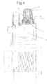
- Figure 4 shows an accumulator device of this invention integrated into an electrically-driven pump.
- the moving element 3 does not include a magnet 6 and thus acts as a simple water-accumulation device.
- the accumulator device integrated into the electrically-driven pump to include a magnet 6 located on the moving support element 3, while said magnet 6 can likewise adopt the function of starting up the pump at a particular pressure by acting on a reed relay or Hall effect sensor or the like.
Landscapes
- Engineering & Computer Science (AREA)
- Physics & Mathematics (AREA)
- Mechanical Engineering (AREA)
- General Engineering & Computer Science (AREA)
- Fluid Mechanics (AREA)
- Thermal Sciences (AREA)
- Chemical & Material Sciences (AREA)
- Combustion & Propulsion (AREA)
- Reciprocating Pumps (AREA)
Applications Claiming Priority (2)
| Application Number | Priority Date | Filing Date | Title |
|---|---|---|---|
| ES200301344A ES2265198A1 (es) | 2003-06-06 | 2003-06-06 | Dispositivo acumulador para una instalacion hidraulica y electrobomba que comprende dicho dispositivo. |
| ES200301344 | 2003-06-06 |
Publications (1)
| Publication Number | Publication Date |
|---|---|
| EP1528261A1 true EP1528261A1 (fr) | 2005-05-04 |
Family
ID=33484267
Family Applications (1)
| Application Number | Title | Priority Date | Filing Date |
|---|---|---|---|
| EP04102387A Withdrawn EP1528261A1 (fr) | 2003-06-06 | 2004-05-28 | Dispositif d'accumulateur pour un système hydraulique et pompe électrique avec un tel dispositif |
Country Status (3)
| Country | Link |
|---|---|
| US (1) | US20040247447A1 (fr) |
| EP (1) | EP1528261A1 (fr) |
| ES (1) | ES2265198A1 (fr) |
Families Citing this family (3)
| Publication number | Priority date | Publication date | Assignee | Title |
|---|---|---|---|---|
| EP2535599A1 (fr) * | 2011-06-17 | 2012-12-19 | Gasparin, Giulia | Vase d'expansion avec dispositif résilient |
| JP2017065575A (ja) * | 2015-09-30 | 2017-04-06 | マツダ株式会社 | 車両の回生システム |
| DE102020101128A1 (de) | 2020-01-20 | 2021-07-22 | Schaeffler Technologies AG & Co. KG | Druckspeichersystem zur hydraulischen Getriebesteuerung |
Citations (3)
| Publication number | Priority date | Publication date | Assignee | Title |
|---|---|---|---|---|
| EP0321376A2 (fr) * | 1987-12-18 | 1989-06-21 | Fernando Banus Garcia | Appareil pour contrôler la mise en marche et l'arrêt d'une pompe hydraulique |
| US5727529A (en) * | 1994-01-14 | 1998-03-17 | Walbro Corporation | Pressure control valve for a fuel system |
| DE19709779A1 (de) * | 1997-03-10 | 1998-09-17 | Itt Mfg Enterprises Inc | Druckmittelspeicher |
Family Cites Families (9)
| Publication number | Priority date | Publication date | Assignee | Title |
|---|---|---|---|---|
| US2345124A (en) * | 1941-12-01 | 1944-03-28 | New York Air Brake Co | Accumulator |
| US2299611A (en) * | 1942-06-03 | 1942-10-20 | United Aircraft Prod | Pressure accumulator |
| US3559727A (en) * | 1968-12-20 | 1971-02-02 | United Aircraft Prod | Accumulator-reservoir in a cooling system |
| US4723577A (en) * | 1986-10-22 | 1988-02-09 | Sundstrand Corporation | Thermal expansion reservoir |
| US4836409A (en) * | 1988-02-18 | 1989-06-06 | Amtrol Inc. | Integral diaphragm-liner bladder for hydropneumatic tank |
| US5590631A (en) * | 1994-01-14 | 1997-01-07 | Walbro Corporation | Fuel system accumulator |
| US5868168A (en) * | 1997-08-04 | 1999-02-09 | Hydril Company | Pulsation dampener diaphragm |
| ES1039006Y (es) * | 1997-12-22 | 1999-03-01 | Ind Ibaiondo S A | Vaso de expansion con membrana fija, perfeccionado |
| US6758657B1 (en) * | 2002-06-20 | 2004-07-06 | The Gorman-Rupp Company | Electromagnetically driven diaphragm pump |
-
2003
- 2003-06-06 ES ES200301344A patent/ES2265198A1/es active Pending
-
2004
- 2004-05-28 EP EP04102387A patent/EP1528261A1/fr not_active Withdrawn
- 2004-06-03 US US10/860,738 patent/US20040247447A1/en not_active Abandoned
Patent Citations (3)
| Publication number | Priority date | Publication date | Assignee | Title |
|---|---|---|---|---|
| EP0321376A2 (fr) * | 1987-12-18 | 1989-06-21 | Fernando Banus Garcia | Appareil pour contrôler la mise en marche et l'arrêt d'une pompe hydraulique |
| US5727529A (en) * | 1994-01-14 | 1998-03-17 | Walbro Corporation | Pressure control valve for a fuel system |
| DE19709779A1 (de) * | 1997-03-10 | 1998-09-17 | Itt Mfg Enterprises Inc | Druckmittelspeicher |
Also Published As
| Publication number | Publication date |
|---|---|
| ES2265198A1 (es) | 2007-02-01 |
| US20040247447A1 (en) | 2004-12-09 |
Similar Documents
| Publication | Publication Date | Title |
|---|---|---|
| EP3239682B1 (fr) | Dispositif de détection de fuite et système d'eau comprenant un dispositif de détection de fuite | |
| KR101688404B1 (ko) | 비례식 스로틀 밸브 | |
| RU2666469C2 (ru) | Регулятор подачи воды и способ управления подачей воды | |
| JP6367645B2 (ja) | ベローズポンプ装置 | |
| EP1225333A3 (fr) | Soupape de contrôle pour un compresseur à plateau en biais à capacité variable | |
| CN106481609A (zh) | 电磁比例控制阀系统 | |
| EP0640765A1 (fr) | Dispositif électro-mécanique pour la protection d'une pompe en l'absence d'eau | |
| US20090238700A1 (en) | Equipment for continuous regulation of the flow rate of reciprocating compressors | |
| WO2017006341A1 (fr) | Dispositif de régulation automatique d'écoulement de fluide pour l'arrêt de l'écoulement d'un fluide courant | |
| EP1528261A1 (fr) | Dispositif d'accumulateur pour un système hydraulique et pompe électrique avec un tel dispositif | |
| KR20080089588A (ko) | 펌핑 중인 매질에서의 방출 맥동을 감쇠시키는 가스 용적감쇠 장치 | |
| EP1313976A1 (fr) | Dispositif de commande automatique de niveau d'eau comprenant un regleur a flotteur et a plusieurs orifices de sortie | |
| CN102301137B (zh) | 在气体压缩机的进气阀中致动的系统 | |
| KR102530260B1 (ko) | 전자 비례 밸브 | |
| US9958083B1 (en) | Force limited valve actuator and method therefor | |
| CN111226065B (zh) | 双设定点压力调节系统 | |
| JP2005291411A (ja) | 過流防止弁 | |
| SE518374C2 (sv) | Tryckluftförsörjningsanläggning för fordon med en anordning för avkänning av påskjutningsfaser samt förfarande för desamma | |
| JP2006266497A (ja) | バネシステム及びバネシステムを備えた乗り物座席 | |
| WO2024068424A1 (fr) | Ensemble dispositif de filtration avec unité de commutateur de dérivation passive | |
| US9752700B2 (en) | Valve device and use of such a valve device | |
| KR100701053B1 (ko) | 단속밸브 겸용 감압변 | |
| KR20170049832A (ko) | 분수밸브 | |
| KR101172484B1 (ko) | 압력 제어용 유압 장치 | |
| JP7781679B2 (ja) | 排水システム |
Legal Events
| Date | Code | Title | Description |
|---|---|---|---|
| PUAI | Public reference made under article 153(3) epc to a published international application that has entered the european phase |
Free format text: ORIGINAL CODE: 0009012 |
|
| AK | Designated contracting states |
Kind code of ref document: A1 Designated state(s): AT BE BG CH CY CZ DE DK EE ES FI FR GB GR HU IE IT LI LU MC NL PL PT RO SE SI SK TR |
|
| AX | Request for extension of the european patent |
Extension state: AL HR LT LV MK |
|
| 17P | Request for examination filed |
Effective date: 20051102 |
|
| AKX | Designation fees paid |
Designated state(s): AT BE BG CH CY CZ DE DK EE ES FI FR GB GR HU IE IT LI LU MC NL PL PT RO SE SI SK TR |
|
| 17Q | First examination report despatched |
Effective date: 20061117 |
|
| STAA | Information on the status of an ep patent application or granted ep patent |
Free format text: STATUS: THE APPLICATION IS DEEMED TO BE WITHDRAWN |
|
| 18D | Application deemed to be withdrawn |
Effective date: 20070530 |