EP1528233A1 - Brennraumkolben um Russbildung zu vermindern - Google Patents
Brennraumkolben um Russbildung zu vermindern Download PDFInfo
- Publication number
- EP1528233A1 EP1528233A1 EP04300742A EP04300742A EP1528233A1 EP 1528233 A1 EP1528233 A1 EP 1528233A1 EP 04300742 A EP04300742 A EP 04300742A EP 04300742 A EP04300742 A EP 04300742A EP 1528233 A1 EP1528233 A1 EP 1528233A1
- Authority
- EP
- European Patent Office
- Prior art keywords
- piston
- bowl
- combustion chamber
- lip
- fuel
- Prior art date
- Legal status (The legal status is an assumption and is not a legal conclusion. Google has not performed a legal analysis and makes no representation as to the accuracy of the status listed.)
- Withdrawn
Links
- 238000002485 combustion reaction Methods 0.000 title claims abstract description 24
- 239000004071 soot Substances 0.000 title description 4
- 239000000446 fuel Substances 0.000 claims abstract description 16
- 230000002093 peripheral effect Effects 0.000 claims abstract description 7
- 238000002347 injection Methods 0.000 claims abstract description 4
- 239000007924 injection Substances 0.000 claims abstract description 4
- 239000006185 dispersion Substances 0.000 description 8
- 238000004519 manufacturing process Methods 0.000 description 5
- 230000006835 compression Effects 0.000 description 4
- 238000007906 compression Methods 0.000 description 4
- 238000009826 distribution Methods 0.000 description 4
- 238000002513 implantation Methods 0.000 description 3
- 239000003344 environmental pollutant Substances 0.000 description 2
- 238000005304 joining Methods 0.000 description 2
- 231100000719 pollutant Toxicity 0.000 description 2
- 230000015572 biosynthetic process Effects 0.000 description 1
- 239000003517 fume Substances 0.000 description 1
- 239000007789 gas Substances 0.000 description 1
- 238000000034 method Methods 0.000 description 1
- 238000012986 modification Methods 0.000 description 1
- 230000004048 modification Effects 0.000 description 1
- 210000002445 nipple Anatomy 0.000 description 1
Images
Classifications
-
- F—MECHANICAL ENGINEERING; LIGHTING; HEATING; WEAPONS; BLASTING
- F02—COMBUSTION ENGINES; HOT-GAS OR COMBUSTION-PRODUCT ENGINE PLANTS
- F02F—CYLINDERS, PISTONS OR CASINGS, FOR COMBUSTION ENGINES; ARRANGEMENTS OF SEALINGS IN COMBUSTION ENGINES
- F02F3/00—Pistons
- F02F3/26—Pistons having combustion chamber in piston head
-
- F—MECHANICAL ENGINEERING; LIGHTING; HEATING; WEAPONS; BLASTING
- F02—COMBUSTION ENGINES; HOT-GAS OR COMBUSTION-PRODUCT ENGINE PLANTS
- F02B—INTERNAL-COMBUSTION PISTON ENGINES; COMBUSTION ENGINES IN GENERAL
- F02B23/00—Other engines characterised by special shape or construction of combustion chambers to improve operation
- F02B23/02—Other engines characterised by special shape or construction of combustion chambers to improve operation with compression ignition
- F02B23/06—Other engines characterised by special shape or construction of combustion chambers to improve operation with compression ignition the combustion space being arranged in working piston
- F02B23/0645—Details related to the fuel injector or the fuel spray
- F02B23/0648—Means or methods to improve the spray dispersion, evaporation or ignition
- F02B23/0651—Means or methods to improve the spray dispersion, evaporation or ignition the fuel spray impinging on reflecting surfaces or being specially guided throughout the combustion space
-
- F—MECHANICAL ENGINEERING; LIGHTING; HEATING; WEAPONS; BLASTING
- F02—COMBUSTION ENGINES; HOT-GAS OR COMBUSTION-PRODUCT ENGINE PLANTS
- F02B—INTERNAL-COMBUSTION PISTON ENGINES; COMBUSTION ENGINES IN GENERAL
- F02B23/00—Other engines characterised by special shape or construction of combustion chambers to improve operation
- F02B23/02—Other engines characterised by special shape or construction of combustion chambers to improve operation with compression ignition
- F02B23/06—Other engines characterised by special shape or construction of combustion chambers to improve operation with compression ignition the combustion space being arranged in working piston
- F02B23/0672—Omega-piston bowl, i.e. the combustion space having a central projection pointing towards the cylinder head and the surrounding wall being inclined towards the cylinder center axis
-
- F—MECHANICAL ENGINEERING; LIGHTING; HEATING; WEAPONS; BLASTING
- F02—COMBUSTION ENGINES; HOT-GAS OR COMBUSTION-PRODUCT ENGINE PLANTS
- F02B—INTERNAL-COMBUSTION PISTON ENGINES; COMBUSTION ENGINES IN GENERAL
- F02B2275/00—Other engines, components or details, not provided for in other groups of this subclass
- F02B2275/14—Direct injection into combustion chamber
-
- F—MECHANICAL ENGINEERING; LIGHTING; HEATING; WEAPONS; BLASTING
- F02—COMBUSTION ENGINES; HOT-GAS OR COMBUSTION-PRODUCT ENGINE PLANTS
- F02B—INTERNAL-COMBUSTION PISTON ENGINES; COMBUSTION ENGINES IN GENERAL
- F02B23/00—Other engines characterised by special shape or construction of combustion chambers to improve operation
- F02B23/02—Other engines characterised by special shape or construction of combustion chambers to improve operation with compression ignition
- F02B23/06—Other engines characterised by special shape or construction of combustion chambers to improve operation with compression ignition the combustion space being arranged in working piston
- F02B23/0618—Other engines characterised by special shape or construction of combustion chambers to improve operation with compression ignition the combustion space being arranged in working piston having in-cylinder means to influence the charge motion
- F02B23/0621—Squish flow
-
- F—MECHANICAL ENGINEERING; LIGHTING; HEATING; WEAPONS; BLASTING
- F02—COMBUSTION ENGINES; HOT-GAS OR COMBUSTION-PRODUCT ENGINE PLANTS
- F02B—INTERNAL-COMBUSTION PISTON ENGINES; COMBUSTION ENGINES IN GENERAL
- F02B3/00—Engines characterised by air compression and subsequent fuel addition
- F02B3/06—Engines characterised by air compression and subsequent fuel addition with compression ignition
-
- Y—GENERAL TAGGING OF NEW TECHNOLOGICAL DEVELOPMENTS; GENERAL TAGGING OF CROSS-SECTIONAL TECHNOLOGIES SPANNING OVER SEVERAL SECTIONS OF THE IPC; TECHNICAL SUBJECTS COVERED BY FORMER USPC CROSS-REFERENCE ART COLLECTIONS [XRACs] AND DIGESTS
- Y02—TECHNOLOGIES OR APPLICATIONS FOR MITIGATION OR ADAPTATION AGAINST CLIMATE CHANGE
- Y02T—CLIMATE CHANGE MITIGATION TECHNOLOGIES RELATED TO TRANSPORTATION
- Y02T10/00—Road transport of goods or passengers
- Y02T10/10—Internal combustion engine [ICE] based vehicles
- Y02T10/12—Improving ICE efficiencies
Definitions
- the present invention relates to a piston for a chamber of multi-cylinder direct injection and spark ignition engine combustion Diesel cycle compression, intended to reduce emissions of soot.
- Combustion chambers for combustion ignition engines compression are formed by a cylinder in which a piston is adapted to slide, said cylinder being closed by a breech portion disposed opposite a free wall of the piston.
- the pistons comprise a cavity forming a bowl
- the edge of the bowl includes a lip having mainly the function of guide the combustion into the bottom of the bowl.
- the bowl comprises a bump similar to a lip that forms an angle of about 30 ° with the axis of piston. This hump serves to prevent the combustion of extend into the hunting area.
- An object of the present invention is to provide a piston which solves this problem.
- a piston for combustion chamber of direct injection and compression ignition engine formed by a cylinder in which a piston is adapted to slide, the piston having a bowl-shaped cavity, the surface forming the bowl having a projecting central nipple and a peripheral part surrounded by a annular hunting zone, characterized in that the bowl inlet comprises a lip whose face directed towards the interior of the bowl forms a neighboring angle 90 ° with a fuel jet of an injector placed substantially in the axis of the piston.
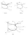
- FIGS. 1, 2A and 2b In a combustion chamber of a combustion engine internal compression ignition, a form of revolution has been machined in the piston 14 to form a cavity 10.
- the combustion chamber is also defined by a portion of a breech for example in front flat, which closes a cylinder in which the piston 14 can slide.
- the bowl surface 18 has a peripheral portion 23 which is surrounded by an annular hunting zone 24 joining the wall internal part of the cylinder, the peripheral portion 23 comprises a lip 26 of re-entrant type.
- Figures 2A and 2B show a variant of lip shape 126 of the state of the art.
- the lip 126 substantially forms a surface cylindrical parallel to the axis of the piston 14.
- the height of the lip 126 is planned to take into account a variation of the depth of implantation of an injector placed substantially of axis years of the piston 14 in order to maintain a distribution of fuel between the bottom of the bowl 18 and has identical hunting area from one engine to another. Indeed, during the manufacture and assembly of the motors there may be dispersions which generate a variation in the implantation of the injector. It can penetrate more or less into the combustion chamber.
- this form does not allow for taking into account the variations in the web angle of the injector. This variation is mainly due to the manufacturing dispersions of the injectors. So, if the lap angle is more closed than the nominal lap angle, the distance between the nozzle of the injector and the lip is larger and the lip reflects the jet of fuel in the bowl 18. Otherwise, the lip 126 reflects the fuel jet upwards which results in the formation of soot important during combustion.
- the lip 126 is rounded and thin. This shape makes it possible to optimize the shape of the cavity by making it less deep.
- the dispersions of manufacture and assembly of engines can cause large variations in the distribution of the fuel in the hunting area which increases the amount of pollutant generated during combustion.
- Figure 1 illustrates a combustion chamber portion 10 according to the invention which is delimited in Figure 1 by a portion a cylinder head (not shown), for example, with a flat front of an engine, which closes a cylinder in which a piston 14 is located in a top dead center position.
- the piston 14 has a machined cavity around the central axis A of the piston 14 so as to form a bowl forming surface 18.
- This surface forming a bowl 18, has a projecting central stud 20 whose axis of symmetry is confused with the central axis A of the piston 14.
- An injector protruding from the breech portion situated opposite the piston 14, is intended to inject the fuel into the combustion chamber 10.
- the bowl surface 18 has a portion peripheral 23 which is surrounded by an annular hunting zone 24 joining the inner wall of the cylinder.
- the part peripheral 23 includes a lip 26 in the inner face directed towards the axis of the piston is substantially perpendicular to the direction of the jets C fuel from the injector.
- This particular orientation of the lip with respect to the jet of fuel makes it possible to obtain a constant angle between the fuel jets C and the lip 26 even in case of dispersion of the manufacture of the piston and / or the injector. Indeed, even in the event of dispersion of the slick angle of the injector angle between the fuel jets C and the lip remains very close 90 °, at most 1 or 2 °. Therefore, the fuel distribution between the bowl 18 and the hunting area remains substantially the same of a cylinder to another and from one engine to another, and in any case remains very next to the nominal conditions.
- the surface of the lip is substantially flat and at a height determined to take into account the variations of position of the nozzle of the injector in the combustion chamber. Indeed, even if injector nozzle height varies because, for example, of a Geometric dispersion of the injector, the C jets of fuel will be deflected by the lip because of the height and the flat surface and this of the same way since the angle of impact on the lip 26 will be the same (about 90 °).
- the height of the lip will be between 2 and 8 mm.
- the The upper edge of the bowl 18 comprises a shoulder 25 of concave shape.
Landscapes
- Engineering & Computer Science (AREA)
- Chemical & Material Sciences (AREA)
- Combustion & Propulsion (AREA)
- Mechanical Engineering (AREA)
- General Engineering & Computer Science (AREA)
- Dispersion Chemistry (AREA)
- Combustion Methods Of Internal-Combustion Engines (AREA)
Applications Claiming Priority (2)
| Application Number | Priority Date | Filing Date | Title |
|---|---|---|---|
| FR0350770A FR2861809A1 (fr) | 2003-11-03 | 2003-11-03 | Piston pour chambre de combustion destinee a reduire les emissions de suies |
| FR0350770 | 2003-11-03 |
Publications (1)
| Publication Number | Publication Date |
|---|---|
| EP1528233A1 true EP1528233A1 (de) | 2005-05-04 |
Family
ID=34400935
Family Applications (1)
| Application Number | Title | Priority Date | Filing Date |
|---|---|---|---|
| EP04300742A Withdrawn EP1528233A1 (de) | 2003-11-03 | 2004-10-28 | Brennraumkolben um Russbildung zu vermindern |
Country Status (2)
| Country | Link |
|---|---|
| EP (1) | EP1528233A1 (de) |
| FR (1) | FR2861809A1 (de) |
Cited By (1)
| Publication number | Priority date | Publication date | Assignee | Title |
|---|---|---|---|---|
| WO2017108837A1 (en) * | 2015-12-22 | 2017-06-29 | Volvo Truck Corporation | A piston crown for an internal combustion engine |
Citations (7)
| Publication number | Priority date | Publication date | Assignee | Title |
|---|---|---|---|---|
| DE1526313A1 (de) * | 1963-10-10 | 1969-02-06 | Maschf Augsburg Nuernberg Ag | Luftverdichtende selbstzuendende Kolbenbrennkraftmaschine |
| JPS6032929A (ja) * | 1983-08-03 | 1985-02-20 | Yanmar Diesel Engine Co Ltd | 直噴式内燃機関の燃焼室 |
| JPH02248615A (ja) * | 1989-03-22 | 1990-10-04 | Isuzu Motors Ltd | エンジンのピストン |
| US5605126A (en) * | 1993-08-11 | 1997-02-25 | Alcan Deutschland Gmbh | Piston for internal combustion engines, especially diesel engines |
| JPH10159566A (ja) * | 1996-12-03 | 1998-06-16 | Daihatsu Motor Co Ltd | 直噴式ディーゼル機関における燃焼室の構造 |
| JP2001227345A (ja) * | 2000-02-18 | 2001-08-24 | Honda Motor Co Ltd | 燃料直噴式ディーゼルエンジン |
| AT4874U1 (de) * | 2000-07-20 | 2001-12-27 | Avl List Gmbh | Luftverdichtende, ventilgesteuerte brennkraftmaschine |
Family Cites Families (4)
| Publication number | Priority date | Publication date | Assignee | Title |
|---|---|---|---|---|
| US4721080A (en) | 1984-02-15 | 1988-01-26 | Mitsubishi Jidosha Kogyo Kabushiki Kaisha | Structure of combustion chamber in diesel engine |
| JPH07133723A (ja) * | 1993-11-09 | 1995-05-23 | Hino Motors Ltd | 直接噴射式ディーゼルエンジンの燃焼室 |
| JP3689797B2 (ja) * | 1996-10-31 | 2005-08-31 | ヤマハ発動機株式会社 | 自動二輪車の後輪懸架装置 |
| JP4308397B2 (ja) * | 2000-02-17 | 2009-08-05 | 昭和フロント株式会社 | 建築物用開口部枠材 |
-
2003
- 2003-11-03 FR FR0350770A patent/FR2861809A1/fr not_active Withdrawn
-
2004
- 2004-10-28 EP EP04300742A patent/EP1528233A1/de not_active Withdrawn
Patent Citations (7)
| Publication number | Priority date | Publication date | Assignee | Title |
|---|---|---|---|---|
| DE1526313A1 (de) * | 1963-10-10 | 1969-02-06 | Maschf Augsburg Nuernberg Ag | Luftverdichtende selbstzuendende Kolbenbrennkraftmaschine |
| JPS6032929A (ja) * | 1983-08-03 | 1985-02-20 | Yanmar Diesel Engine Co Ltd | 直噴式内燃機関の燃焼室 |
| JPH02248615A (ja) * | 1989-03-22 | 1990-10-04 | Isuzu Motors Ltd | エンジンのピストン |
| US5605126A (en) * | 1993-08-11 | 1997-02-25 | Alcan Deutschland Gmbh | Piston for internal combustion engines, especially diesel engines |
| JPH10159566A (ja) * | 1996-12-03 | 1998-06-16 | Daihatsu Motor Co Ltd | 直噴式ディーゼル機関における燃焼室の構造 |
| JP2001227345A (ja) * | 2000-02-18 | 2001-08-24 | Honda Motor Co Ltd | 燃料直噴式ディーゼルエンジン |
| AT4874U1 (de) * | 2000-07-20 | 2001-12-27 | Avl List Gmbh | Luftverdichtende, ventilgesteuerte brennkraftmaschine |
Non-Patent Citations (5)
| Title |
|---|
| PATENT ABSTRACTS OF JAPAN vol. 0091, no. 58 (M - 393) 3 July 1985 (1985-07-03) * |
| PATENT ABSTRACTS OF JAPAN vol. 0145, no. 75 (M - 1062) 20 December 1990 (1990-12-20) * |
| PATENT ABSTRACTS OF JAPAN vol. 1995, no. 08 29 September 1995 (1995-09-29) * |
| PATENT ABSTRACTS OF JAPAN vol. 1998, no. 11 30 September 1998 (1998-09-30) * |
| PATENT ABSTRACTS OF JAPAN vol. 2000, no. 25 12 April 2001 (2001-04-12) * |
Cited By (4)
| Publication number | Priority date | Publication date | Assignee | Title |
|---|---|---|---|---|
| WO2017108837A1 (en) * | 2015-12-22 | 2017-06-29 | Volvo Truck Corporation | A piston crown for an internal combustion engine |
| CN108474290A (zh) * | 2015-12-22 | 2018-08-31 | 沃尔沃卡车集团 | 用于内燃机的活塞冠 |
| US10738682B2 (en) | 2015-12-22 | 2020-08-11 | Volvo Truck Corporation | Piston crown for an internal combustion engine |
| CN108474290B (zh) * | 2015-12-22 | 2020-10-23 | 沃尔沃卡车集团 | 内燃机装置及车辆 |
Also Published As
| Publication number | Publication date |
|---|---|
| FR2861809A1 (fr) | 2005-05-06 |
Similar Documents
| Publication | Publication Date | Title |
|---|---|---|
| FR2479328A1 (fr) | Moteur a combustion interne a allumage par etincelle | |
| EP2232027A1 (de) | Brennkammer eines verbrennungsmotors | |
| FR3047043A1 (fr) | Moteur a combustion interne a taux de compression variable avec deux zones de melange, notamment pour vehicule automobile et procede d'injection pour un tel moteur. | |
| FR2868480A1 (fr) | Moteur a combustion interne a injection directe | |
| BE388676A (de) | ||
| FR2958977A1 (fr) | Piston pour chambre de combustion de moteur diesel | |
| EP1528233A1 (de) | Brennraumkolben um Russbildung zu vermindern | |
| FR2947009A1 (fr) | Piston pour chambre de combustion de moteur diesel. | |
| FR2487425A1 (fr) | Construction de chambre de combustion pour un moteur a combustion interne | |
| FR2860044A1 (fr) | Chambre de combustion destinee a reduire les emissions de suies | |
| EP0338882B1 (de) | Dieselbrennkraftmaschine mit Vorkammer mit geradem und geneigtem Schusskanal | |
| FR2880915A1 (fr) | Moteur diesel a combustion interne a chambre de combustion presentant une forme de type "col sonique" | |
| EP0889225A1 (de) | Direkteinspritzende Otto-Brennkraftmaschine | |
| EP1861596B1 (de) | Brennkraftmaschine mit direkteinspritzung und eine omega-formige kolbenmulde | |
| EP0879941A1 (de) | Brennkraftmaschine mit Direkteinspritzung und mit Fremdzündung | |
| EP0661423B1 (de) | Dieselbrennkraftmaschine mit am Ausgang der Wirbelkammer gesteuertem Gasstrom | |
| FR2860043A1 (fr) | Piston pour chambre de combustion destinee a reduire les emissions de suies | |
| FR2713282A1 (fr) | Moteur à allumage par compression à injection directe, à combustion améliorée. | |
| EP0983426B1 (de) | Brennkraftmaschine mit fremdzündung | |
| FR2895019A1 (fr) | Bol de piston pour moteur diesel a injection directe | |
| FR2772073A1 (fr) | Moteur a combustion interne a allumage commande et a injection directe | |
| EP1241332A1 (de) | Brennkammerdach | |
| FR2763995A1 (fr) | Moteur a injection directe et allumage commande | |
| FR2859244A1 (fr) | Piston pour moteur a combustion interne a allumage par compression | |
| EP0878613A1 (de) | Direkteinspritzbrennkraftmaschine mit Zündvorrichtung |
Legal Events
| Date | Code | Title | Description |
|---|---|---|---|
| PUAI | Public reference made under article 153(3) epc to a published international application that has entered the european phase |
Free format text: ORIGINAL CODE: 0009012 |
|
| AK | Designated contracting states |
Kind code of ref document: A1 Designated state(s): AT BE BG CH CY CZ DE DK EE ES FI FR GB GR HU IE IT LI LU MC NL PL PT RO SE SI SK TR |
|
| AX | Request for extension of the european patent |
Extension state: AL HR LT LV MK |
|
| 17P | Request for examination filed |
Effective date: 20051104 |
|
| AKX | Designation fees paid |
Designated state(s): AT BE BG CH CY CZ DE DK EE ES FI FR GB GR HU IE IT LI LU MC NL PL PT RO SE SI SK TR |
|
| STAA | Information on the status of an ep patent application or granted ep patent |
Free format text: STATUS: THE APPLICATION IS DEEMED TO BE WITHDRAWN |
|
| 18D | Application deemed to be withdrawn |
Effective date: 20060607 |