EP1528223A2 - Etude des aubes de turbomachines soumises aux vibrations - Google Patents
Etude des aubes de turbomachines soumises aux vibrations Download PDFInfo
- Publication number
- EP1528223A2 EP1528223A2 EP04256093A EP04256093A EP1528223A2 EP 1528223 A2 EP1528223 A2 EP 1528223A2 EP 04256093 A EP04256093 A EP 04256093A EP 04256093 A EP04256093 A EP 04256093A EP 1528223 A2 EP1528223 A2 EP 1528223A2
- Authority
- EP
- European Patent Office
- Prior art keywords
- vane
- design
- blade
- characteristic
- local
- Prior art date
- Legal status (The legal status is an assumption and is not a legal conclusion. Google has not performed a legal analysis and makes no representation as to the accuracy of the status listed.)
- Withdrawn
Links
- 238000013461 design Methods 0.000 title claims abstract description 140
- 238000000034 method Methods 0.000 claims abstract description 67
- 230000004048 modification Effects 0.000 claims abstract description 20
- 238000012986 modification Methods 0.000 claims abstract description 20
- 238000006073 displacement reaction Methods 0.000 claims description 8
- 230000008719 thickening Effects 0.000 claims description 4
- 238000005094 computer simulation Methods 0.000 claims description 3
- 230000006872 improvement Effects 0.000 claims description 3
- 230000000007 visual effect Effects 0.000 claims description 3
- 230000004075 alteration Effects 0.000 claims description 2
- 238000013507 mapping Methods 0.000 claims description 2
- 230000004044 response Effects 0.000 abstract description 20
- 230000005284 excitation Effects 0.000 abstract description 6
- 238000010408 sweeping Methods 0.000 abstract description 6
- 239000000463 material Substances 0.000 abstract description 4
- 230000009467 reduction Effects 0.000 abstract description 3
- 238000011161 development Methods 0.000 description 16
- 230000018109 developmental process Effects 0.000 description 16
- 230000001186 cumulative effect Effects 0.000 description 13
- 238000011144 upstream manufacturing Methods 0.000 description 11
- 230000008859 change Effects 0.000 description 10
- 238000004458 analytical method Methods 0.000 description 6
- 239000012530 fluid Substances 0.000 description 6
- 230000010363 phase shift Effects 0.000 description 4
- 230000008569 process Effects 0.000 description 4
- 230000001627 detrimental effect Effects 0.000 description 3
- 230000000694 effects Effects 0.000 description 3
- 238000004364 calculation method Methods 0.000 description 2
- 230000000712 assembly Effects 0.000 description 1
- 238000000429 assembly Methods 0.000 description 1
- 230000004323 axial length Effects 0.000 description 1
- 238000004590 computer program Methods 0.000 description 1
- 238000013016 damping Methods 0.000 description 1
- 230000003247 decreasing effect Effects 0.000 description 1
- 238000010586 diagram Methods 0.000 description 1
- 230000000704 physical effect Effects 0.000 description 1
- 230000000750 progressive effect Effects 0.000 description 1
- 238000012360 testing method Methods 0.000 description 1
Images


Classifications
-
- F—MECHANICAL ENGINEERING; LIGHTING; HEATING; WEAPONS; BLASTING
- F01—MACHINES OR ENGINES IN GENERAL; ENGINE PLANTS IN GENERAL; STEAM ENGINES
- F01D—NON-POSITIVE DISPLACEMENT MACHINES OR ENGINES, e.g. STEAM TURBINES
- F01D5/00—Blades; Blade-carrying members; Heating, heat-insulating, cooling or antivibration means on the blades or the members
- F01D5/12—Blades
- F01D5/14—Form or construction
- F01D5/141—Shape, i.e. outer, aerodynamic form
-
- F—MECHANICAL ENGINEERING; LIGHTING; HEATING; WEAPONS; BLASTING
- F01—MACHINES OR ENGINES IN GENERAL; ENGINE PLANTS IN GENERAL; STEAM ENGINES
- F01D—NON-POSITIVE DISPLACEMENT MACHINES OR ENGINES, e.g. STEAM TURBINES
- F01D5/00—Blades; Blade-carrying members; Heating, heat-insulating, cooling or antivibration means on the blades or the members
- F01D5/12—Blades
- F01D5/14—Form or construction
- F01D5/16—Form or construction for counteracting blade vibration
-
- F—MECHANICAL ENGINEERING; LIGHTING; HEATING; WEAPONS; BLASTING
- F04—POSITIVE - DISPLACEMENT MACHINES FOR LIQUIDS; PUMPS FOR LIQUIDS OR ELASTIC FLUIDS
- F04D—NON-POSITIVE-DISPLACEMENT PUMPS
- F04D27/00—Control, e.g. regulation, of pumps, pumping installations or pumping systems specially adapted for elastic fluids
- F04D27/001—Testing thereof; Determination or simulation of flow characteristics; Stall or surge detection, e.g. condition monitoring
-
- F—MECHANICAL ENGINEERING; LIGHTING; HEATING; WEAPONS; BLASTING
- F04—POSITIVE - DISPLACEMENT MACHINES FOR LIQUIDS; PUMPS FOR LIQUIDS OR ELASTIC FLUIDS
- F04D—NON-POSITIVE-DISPLACEMENT PUMPS
- F04D29/00—Details, component parts, or accessories
- F04D29/26—Rotors specially for elastic fluids
- F04D29/32—Rotors specially for elastic fluids for axial flow pumps
- F04D29/321—Rotors specially for elastic fluids for axial flow pumps for axial flow compressors
- F04D29/324—Blades
-
- F—MECHANICAL ENGINEERING; LIGHTING; HEATING; WEAPONS; BLASTING
- F05—INDEXING SCHEMES RELATING TO ENGINES OR PUMPS IN VARIOUS SUBCLASSES OF CLASSES F01-F04
- F05D—INDEXING SCHEME FOR ASPECTS RELATING TO NON-POSITIVE-DISPLACEMENT MACHINES OR ENGINES, GAS-TURBINES OR JET-PROPULSION PLANTS
- F05D2250/00—Geometry
- F05D2250/30—Arrangement of components
- F05D2250/31—Arrangement of components according to the direction of their main axis or their axis of rotation
-
- G—PHYSICS
- G06—COMPUTING; CALCULATING OR COUNTING
- G06F—ELECTRIC DIGITAL DATA PROCESSING
- G06F2111/00—Details relating to CAD techniques
- G06F2111/10—Numerical modelling
-
- G—PHYSICS
- G06—COMPUTING; CALCULATING OR COUNTING
- G06F—ELECTRIC DIGITAL DATA PROCESSING
- G06F30/00—Computer-aided design [CAD]
- G06F30/20—Design optimisation, verification or simulation
-
- Y—GENERAL TAGGING OF NEW TECHNOLOGICAL DEVELOPMENTS; GENERAL TAGGING OF CROSS-SECTIONAL TECHNOLOGIES SPANNING OVER SEVERAL SECTIONS OF THE IPC; TECHNICAL SUBJECTS COVERED BY FORMER USPC CROSS-REFERENCE ART COLLECTIONS [XRACs] AND DIGESTS
- Y10—TECHNICAL SUBJECTS COVERED BY FORMER USPC
- Y10S—TECHNICAL SUBJECTS COVERED BY FORMER USPC CROSS-REFERENCE ART COLLECTIONS [XRACs] AND DIGESTS
- Y10S416/00—Fluid reaction surfaces, i.e. impellers
- Y10S416/02—Formulas of curves
Definitions
- the present invention relates to methods and systems for designing components that, in use, are expected to encounter vibratory loading.
- the invention has applicability in the field of aero engines and turbomachinery.
- a typical turbine engine (or typical turbomachinery) contains several annular fluid-conveying ducts which form, e.g., the compressor or turbine sections of the engine.
- Each of these ducts contains a number of blades or vanes (which are henceforth called guide vanes or simply vanes) circumferentially distributed in one or more vane assemblies in the duct.
- the vanes are categorized as rotor blades or stator vanes depending on whether or not the respective vane rotates in the duct when the engine operates.
- each vane has a surface that extends radially across the duct.
- vanes When subjected to high speed airflows, vanes typically become susceptible to large amplitude vibration, often caused by unsteady aerodynamic forces.
- the unsteady aerodynamic forces are caused by the "wakes" of components upstream in the fluid-conveying duct. This is illustrated by the following example in which the vane of interest is a rotating compressor blade. Note that the vanes can also be subjected to forcing from the downstream pressure fields (e.g. from downstream vanes).
- a set of stator blades are provided, situated upstream of the compressor blade.
- the function of the stator blades is to adjust the direction of fluid flow towards the compressor blades.
- Each stator blade has an associated wake. As the compressor blade rotates, it "sees" a wake from each stator blade in turn.
- the frequency f at which the compressor blade sees a stator wake is therefore equal to the number of complete revolutions of the compressor blade per second multiplied by the number of stator blades in the set of stator blades (assuming that the stator blades are circumferentially equispaced from each other).
- the travel of the compressor blade through the wakes of the stator blades causes varying aerodynamic forces to act on the compressor blade.
- the frequency of variation of these forces is f .
- Vibration of the blade resulting from the varying aerodynamic forces is termed the "forced response". If f matches a natural frequency of a mode of vibration of the compressor blade and if the unsteady aerodynamic forcing matches the associated modeshape, then the compressor blade will resonate. Consequently, the amplitude of vibration of the compressor blade will be relatively large. Such vibrations are detrimental to the compressor blade, and may result in failure of the blade. It is desirable to reduce the detrimental effect of forced response in order to avoid failure of components in the aero engine or turbomachinery of interest.
- Another possible solution is to decrease the forcing on the vanes, i.e., in the example above, by decreasing the variation in aerodynamic forces seen by the compressor blade.
- One way to this would be to locate the compressor blades further downstream of the stator blades. However, this increases the axial length of the engine/machinery and thus increases the total weight. This is undesirable.
- the inventors have realised that the above problem may be addressed by altering the vane of interest in order to alter its forced response at a particular frequency. In particular, they have realised that the problem may be addressed during the design stage of the vane.
- the local modal force MF L provides a measure of the likely forced response of a vane at that local element.
- MF L is the scalar product of two vector quantities, ⁇ F L and ⁇ x L .
- ⁇ F L is the local unsteady aerodynamic force acting on the surface of the local element of the vane.
- ⁇ x L is the modeshape of the local element of the vane.
- the modeshape is the actual vibrating shape of a vane at a natural frequency.
- the modeshape is a physical property of the vane which depends on its geometry and the material which makes it.
- the present invention provides a modification of a first vane design to give a second vane design, the second design having a reduced correlation between:
- the varying force (a) may be considered to have a shape (sometimes referred to as a "pressure shape").
- the vibrational mode (b) may be considered to have a displacement characteristic or modeshape.
- the matching between the modeshape and pressure shape is minimised.
- the present invention provides a method of designing a vane using a quantitative characteristic which is a measure of correlation between:
- the vibrational mode is characterised by a displacement characteristic.
- This may be a modeshape of the vane.
- the quantitative characteristic may be the shape match between (a) and (b).
- the varying force to which the vane is to be subjected is an unsteady aerodynamic force.
- Such forces are often complex and usually include more than one frequency component.
- the characteristic frequency of the varying force of interest will be the dominant frequency of the force.
- the dominant frequency may be the frequency component with the highest amplitude.
- the varying force may include more than one characteristic frequency.
- the vibrational mode of the vane may correspond to or be excited by one or more of the characteristic frequencies of the varying force.
- the first and second designs of the vane are numerical or computational models of the vane.
- the quantitative characteristic may be representative of a local element of the vane, e.g. a local element of the surface of the vane. As set out below, such local quantitative characteristics may be of use in preparing representative maps of the vane to highlight problem areas of the vane. Alternatively, the quantitative characteristic may be cumulative in the sense of being representative of a larger region of the vane. Such a cumulative characteristic allows a more general indication of the likely response of the vane to specified operational conditions.
- the quantitative characteristic preferably is a scalar quantity. It may be determined by calculating the scalar (dot) product of two vector quantities.
- the first vector quantity is an indication of the varying force to which the vane is to be subjected.
- this first vector quantity is calculated or estimated.
- the first vector quantity is ⁇ F L , which is the local unsteady aerodynamic force acting on the surface of a local element of the vane. This may be calculated or estimated using known computational fluid dynamics techniques.
- the second vector quantity in the dot product is a displacement characteristic (modeshape) of a vibrational mode of the vane, associated with the vibrational mode corresponding to the characteristic frequency of the varying force.
- the second vector quantity is ⁇ x L , which is mentioned above.
- the modeshape may be determined using known computer-aided engineering (CAE) techniques such as finite element analysis (FEA).
- the size (e.g. area) of the local element of the vane is determined by the way in which the modeshape ⁇ x L is determined. If this is by finite element analysis, then the meshing arrangement chosen to model the vane usually determines the size of the local element of the vane from which a determination of MF L can be made.
- local quantitative characteristics may be mapped (e.g. graphically) to give a visual representation of the value of the local quantitative characteristics across the surface of the vane.
- the visual representations of the first and second designs may then be compared to assess the correlation between factors (a) and (b) for the different designs.
- This can be a useful tool for looking for localised areas on the vane which are likely to give a high amplitude of forced response under the condition modelled.
- a localised area in the first design which has a high forced response can be re-designed (to give the second design) and the same localised area can be analysed in the second design to check the change in the forced response.
- the method may further include the step of determining a line-cumulative quantitative characteristic. Preferably, this is done by summing quantitative characteristics determined for local vane elements located along a line. Preferably, the local vane elements are sequential and/or contiguous. For example, the line may follow an aerofoil surface of the vane.
- a longitudinal axis of the vane For a vane that extends (or is intended to extend) in a fluid-conveying duct of a turbine engine or turbomachinery, it is possible to define a longitudinal axis of the vane as an axis extending substantially along the vane and substantially radially from the axis of the turbine engine or turbomachinery.
- the line along which the line-cumulative quantitative characteristic is determined may extend substantially longitudinally along the vane.
- the line along which the line-cumulative quantitative characteristic is determined may extend substantially transversely along the vane.
- the transverse direction is substantially normal to the longitudinal direction.
- the line may extend substantially along the chord direction of the vane.
- the method may further include the step of determining an area-cumulative quantitative characteristic (or a surface-cumulative qualitative characteristic). This may be done by summing line-cumulative quantitative characteristics, each line-cumulative quantitative characteristic having been determined for local vane elements located along a line, as mentioned above. Each line typically intersects (preferably substantially perpendicularly) an area-summation line. The summation of the line-cumulative quantitative characteristics may be performed along the area summation line.
- the lines for which the line-cumulative quantitative characteristics are determined preferably lie side-by-side along the area of the vane of interest.
- the area may be, for example, the whole or a portion of a major face of the vane, e.g. an aerofoil-shaped face of the vane.
- the area-cumulative quantitative characteristic may be determined by summing quantitative characteristics determined for local vane elements located on the area of interest of the vane.
- the local vane elements are contiguous. This step may be useful in particular if the area of interest is not a straight-sided or regular shape. Use of this step avoids the need to determine first the line-cumulative data before determining the area-cumulative data.
- the area-cumulative (or surface-cumulative) quantitative characteristic is a scalar quantity.
- an area-cumulative quantitative characteristic for the first design may be compared in a straightforward manner with an area-cumulative quantitative characteristic for the second design.
- the line-cumulative quantitative characteristic is a scalar quantity. Therefore, the line-cumulative quantitative characteristics for the first design may be compared in a straightforward manner with the line-cumulative quantitative characteristics for the second design.
- the method is iterative.
- the method may be repeated once or more than once, using the second design of the first iteration of the method as the first design of the second iteration of the method.
- 5 or 6 iterations may be performed.
- up to 10, 11 or 12 iterations may be performed.
- the second development of the invention relates to the ways in which the vane design may be altered in order to reduce the correlation between (a) and (b) (e.g. to reduce the matching of the pressure shape and the modeshape) in the first development.
- the method of the first development is incorporated into an optimisation procedure for the design of the vane.
- the design of the vane may be altered in different ways during the design optimisation procedure.
- the term "design" of the vane is intended to include not just the geometrical shape of the vane (length, chord width, thickness, etc.) but also, for example, the configuration of the vane with respect to the fluid-conveying duct in which it is to be mounted.
- the vane design may be modified to change any one (or more) of the lean, sweep or twist of the vane.
- the lean of the vane is preferably to be understood as the orientation of the vane in a circumferential direction, i.e. substantially along the circumferential direction of the fluid-conveying duct which is substantially perpendicular to the overall direction fluid movement along the duct.
- the degree of lean of the vane may change along the longitudinal axis of the vane, e.g. it may increase, decrease or vary in a more complex manner.
- the longitudinal axis of the vane need not be a straight line. Instead, it may be the mid-chord line of the vane.
- the sweep of the vane is preferably to be understood as the orientation of the vane in a direction substantially parallel to the overall direction of fluid movement along the fluid-conveying duct.
- the sweep of the vane may be in an upstream or downstream direction.
- the degree of sweep of the vane may change along the longitudinal axis of the vane, e.g. it may increase, decrease or vary in a more complex manner.
- the twist of the vane is preferably to be understood as the orientation of the vane about its own longitudinal axis.
- the degree of twist of the vane may change along the longitudinal axis of the vane, e.g. it may increase, decrease or vary in a more complex manner.
- the design of the blade may be modified by, in the design model, adding or removing material from localised parts of the vane. This may be done by thickening or thinning one or more regions of the vane. Alternatively, it may be done by completely removing a portion of the vane, e.g. one or more corners.
- the region of the vane modified in this manner may be a region identified as having a high correlation between factors (a) and (b).
- the modification of the vane design results in an alteration of the position of a nodal line in the modeshape of the vane.
- a nodal line may be understood as a line of zero or substantially zero deformation in the modeshape.
- the nodal lines may be repositioned by modifying at least one of the lean, sweep and twist of the vane design. Additionally or alternatively, the geometry of the vane design and/or the proportions of the vane design may be modified to reposition the nodal lines. Furthermore, the nodal lines may be repositioned by modifying the material of the vane design. These changes (individually or collectively) can result in modification of the stiffness distribution in the vane. Local or global changes in the stiffness have the effect of repositioning the nodal lines of the vane modeshape.
- Phase shifts between the modeshape and pressure shape may be introduced by changing the modeshape.
- a phase shift may be introduced by ensuring that the force reaches the vane at a different time instant.
- phase shifts may be introduced by leaning or sweeping the vane.
- phase shifts may be introduced by changing the spacing between rotor vanes and stator vanes, or by changing the shape of the stator (e.g. overall shape or shape of individual stator vanes).
- the optimisation procedure may be iterative. During the optimisation procedure (which may take place by numerical modelling on a computer) the quantitative characteristic of the first design is compared to a threshold quantitative characteristic. The result of that comparison (e.g. "pass” or "fail”) may then be used as a basis, in a subsequent step, for modifying the first design to give the second design. Preferably, a corresponding quantitative characteristic is determined for the second design in the same way as for the first design. This corresponding quantitative characteristic may then be compared to (a) the threshold quantitative characteristic and/or (b) the quantitative characteristic of the first design. The result of the comparison (a) (e.g. "pass” or "fail”) and/or comparison (b) (e.g.
- the vane design is substantially optimised, i.e. until no substantial improvement (reduction) in quantitative characteristic is seen in a design in comparison to the previous design.
- the second development, and/or any preferred or optional features of the second development may be combined with the first development, and/or any preferred or optional features of the first development.
- further preferred or optional features, which may be incorporated into the first or second developments, are mentioned below.
- the vane is a guide vane for a turbine engine (e.g. an aero engine) or turbomachinery.
- the vane is a blade (particularly a rotor blade) of such an engine or machinery.
- the blade may be a fan blade, compressor blade or turbine blade.
- any of the preferred or optional features of embodiments may be used in any combination.
- any of the preferred or optional features of the first aspect may be used.
- any of the preferred or optional features of the following aspects may be combined with each other or with the first aspect.
- the invention provides a vane or vane design obtained or obtainable by the first aspect.
- the invention provides computer code for implementing the method of the first aspect.
- the invention provides a programmed computer or linked computers operatively configured to implement the method of the first aspect.
- the invention provides a computer programming product (e.g. stored on a data carrier) for implementing the method of the first aspect.
- a blade in particular to a compressor blade of an aero engine.
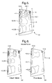
- One such blade is shown schematically in Figs. 1 and 2.
- Fig. 1 shows a drawing of a blade in a non-deformed state. This shape is assumed by this blade when no steady state or vibrational load is applied to the blade.
- Fig. 2 shows a drawing of the same blade as Fig. 1. However, Fig. 2 shows an instantaneous shape of the blade which is different to that of Fig. 1.
- the blade is deformed due to a vibrational load.
- a measure of deformation of local elements of the blade is given by the displacement of each local element with respect to the position of the same local element in its non-deformed state.
- the shaded contours indicate lines of equal displacement. The values shown are normalised between 0 and 1. It can be seen that one corner tip of the blade has a significantly higher normalised displacement than the remainder of the blade.
- the overall shape of the fluid-conveying duct (and therefore the general overall shape of the engine) must be known.
- the exact shape (a first design) of the compressor blade must be known or designed.
- the shape of the parts of the engine upstream must be known.
- the rotor blade will have a set of stator vanes located immediately upstream of it in the duct.
- the stators are shaped and positioned in order to straighten the flow of gas towards the rotor blades.
- gas moves at high speeds through the duct, past the stators.
- the rotor blades rotate during engine operation, and so each blade "sees" a series of stator wakes in the gas flow. These stator wakes are the dominant cause of unsteady aerodynamic forces on the surface of the rotor blade.
- stator vanes which do not rotate
- stator vanes can also see forcing from upstream or downstream rotor blades.
- the rotor blades can "see” wakes from upstream stator vanes as well as downstream pressure field forcing from downstream stator vanes.
- finite element analyses are carried out (as described below) to determine vibration modes and frequency diagrams for various engine operating conditions (e.g. speeds, gas loads and temperatures).
- the unsteady aerodynamic forces ( ⁇ F L ) on the surface of the compressor blade are determined using computational fluid dynamics (CFD).
- CFD computational fluid dynamics
- the factors discussed in the above paragraph are taken into account in a computer model of the conditions at the blade surface.
- ⁇ F L may be determined using known CFD software such as FLUENT, which is available from Fluent, Inc. (10 Cavendish Court, Centerra Park, Riverside, New Hampshire 03766, USA) or from Fluent Europe (Sheffield Airport Business Park, Europa Link, Sheffield, S9 1XU, UK).
- FLUENT Fluent, Inc. (10 Cavendish Court, Centerra Park, Riverside, New Hampshire 03766, USA) or from Fluent Europe (Sheffield Airport Business Park, Europa Link, Sheffield, S9 1XU, UK).
- a proprietary Rolls-Royce software such as code AU3D may be used.
- the unsteady aerodynamic forces acting on the surface of the compressor blade can be measured in a testing engine using strain gauges.
- the levels of forced response of a given vibration mode measured by strain gauges can be expressed in terms of vibration stresses, amplitude-frequency or percentage endurance (ratio of modal vibration stress to vibration strength of the blade).
- a particularly important frequency in engine blade design is the frequency of forcing which the blade is exposed to at normal operation speeds, for example at cruising speeds.
- the excitation or forcing frequency from the upstream blading i.e. pressure pulses called wakes
- the excitation or forcing frequency from the upstream blading may be calculated by multiplying the rotational speed of the rotor by the number of upstream or downstream stator vanes. Note that calculation is done in a similar manner for rotors (rotating parts) relative to stators (non-rotating parts) or vice-versa.
- the modeshapes ⁇ x L are needed for the calculation of the map of the modal force.
- Modeshapes may be calculated using computer-aided engineering techniques such as finite element analysis (FEA).
- FEA finite element analysis
- NASTRAN which is available from Noran Engineering, Inc. (5182 Katella Ave., Suite 201, Los Alamitos, CA 90720-2855, USA).
- Other suitable FEA software packages are ANSYS (available from ANSYS Inc.) and ABAQUS (available from ABAQUS, Inc.).
- a proprietary Rolls-Royce software SC03 may be used.
- the unsteady aerodynamic force vector ⁇ F L and the modeshape ⁇ x L are determined. Then, for each local element L the local modal force MF L is determined, where MF L is the scalar product of the two vector quantities ⁇ F L and ⁇ x L . The value of MF L is then mapped to give a graphical representation of the relative values of MF L across the surface of the blade.
- FIG. 4 An example of a representation of the modeshape of a blade is shown in Fig. 4, for the blade shown in its non-deformed state in Fig. 3.
- Fig. 4 shows shaded contours of equal values of ⁇ X L .
- the contours indicate normalised amplitude variations as well as directions of displacements.
- the vibration mode shown in Fig. 4 is the 2 nd torsion mode.
- the two upper corners of the blade have the highest amplitude variations, and are displaced in opposite directions from each other.
- Blade surface map 10 in Fig. 5 is a representation of the normalised magnitude of MF L across the front surface of the blade. Contours of substantially equal normalised MF L have been drawn as an aid to the eye. Spot values for normalised MF L are given for selected regions. It can be seen from this drawing that much of the surface of the blade has similar values of MF L . However, a regions near the upper left hand side of the blade (marked "+1") and a region at the upper right hand side of the blade (marked "-1"0 have significantly different values of MF L . MF L at these regions is significantly higher than for the remainder of the surface of the blade. These regions have high correlation between the local unsteady aerodynamic force and the local modeshape. As a consequence, these regions are expected to give rise to a high forced response under the conditions modelled. Such regions might give rise to a high cycle fatigue failure of the blade.
- Fig. 5 also shows notional lines x and z . These will be discussed in detail later.
- Fig. 6 shows two blade surface maps 22 and 24.
- the first map 22 is similar to map 10 in Fig. 5.
- the blade surface maps in Fig. 6 are representations of the normalised magnitude of MF L across the front surface of two blades of differing designs. Contours of substantially equal normalised MF L have been drawn as an aid to the eye. Spot values for normalised MF L are given for selected regions.
- Map 22, like map 10 in Fig. 5, shows two regions of high normalised MF L (marked "+1" and "-1", respectively). These regions are regions of high correlation between the local unsteady aerodynamic force and the local modeshape.
- the first map 22 is referred to as the "datum", i.e. it is the first design. This first design may be the design of a known blade.
- the identification of regions of high correlation between the local unsteady aerodynamic force and the local modeshape shows that the blade design needs to be modified in order to reduce MF L at those regions.
- the design modification applied to the datum blade design in Fig. 6 was a combination of leaning, sweeping and twisting.
- a suitable modification has been carried out to the design of blade whose surface values of MF L are mapped in blade surface map 24.
- the corresponding regions at the upper left and right hand sides of map 24 have lower normalised values of MF L (disregarding sign) in comparison to the same regions at the upper left and right hand sides of map 22.
- Figs. 5 and 6 The method illustrated by Figs. 5 and 6 is useful for identifying and addressing problem areas of the blade.
- the iterative design and re-design of the blade can reduce the seriousness of problem areas.
- Such a method is an extension of the method illustrated in Figs. 5 and 6 and is illustrated by Figs. 7 and 8.
- map 10 is a graphical representation of a large number of values MF L for each local element L of the blade surface. Therefore, it is possible to sum up (i.e. integrate) the values MF L to give a cumulative mode force value (MFC area ) for the whole surface (or for just a part of the surface, if desired). This summing may be done either by summing all the elements at once, or by summing MF L for individual lines or rows of local elements and then summing the line-cumulative mode force value (MFC line ) for each of those lines or rows.
- MFC area cumulative mode force value
- the line summing may first be done along rows of elements parallel to axis x .
- Axis x is the transverse (or chord) axis of the blade.
- the summation of the lines is done in direction z in Fig. 5, which is the longitudinal (radial) direction of the blade.
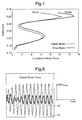
- the progress of the summation is shown graphically in Fig. 7.
- the abscissa shows the cumulative modal force and the ordinate shows the radius which the summation has reached, which is a measure of how far along the blade in direction z the summation has progressed.
- the line for the datum blade design is substantially always at higher cumulative modal force than the line for the final blade design. Note that both cumulative values increase and decrease. This is because the local modal forces can be negative as well as positive. Therefore, a region of negative local modal forces after a region of positive local modal forces can reduce the magnitude of the cumulative modal force.
- the total cumulative modal force (the global modal force) for the final blade design is better (lower) than that of the datum blade design.
- This final value which necessarily takes into account all of the blade surface of interest, is a useful measure of the overall likely forced response of the blade design at the operating conditions selected.
- Fig. 8 shows how the global modal force value for two blade designs varies with time.
- the graph of Fig. 8 was produced using modelled data.
- Each peak in the graph corresponds to a high global modal force for the whole blade, so corresponds to those times during the movement of the blade where its surface is subjected to high aerodynamic force.
- Each peak can therefore be tied in with a corresponding stator blade immediately in front of the modelled compressor blade.
- Line 40 corresponds to the global modal force for a datum blade design.
- the amplitude of the global modal force is high - this is indicative of a high forced response when a blade of that datum design is subjected to the chosen operating conditions.
- Line 42 corresponds to the global modal force for a modified (improved) blade design.
- the amplitude of the global modal force is lower than that of line 40 - this is indicative of a lower forced response when a blade of that modified design is subjected to the chosen operating conditions.
- the modification of the modeshape can be carried out in such a way that the profile of the source of excitation (i.e. the unsteady pressure profile) and the modeshape are mismatched. Ideally, these shapes are outphased in order to become dissimilar, thereby avoiding resonant response and high amplitudes of vibration for that vibrational mode.
- a suitable mismatch between the unsteady pressure profile and the modeshape can be created by modifying the positions of nodal lines in the modeshape. Nodal lines are lines of zero deformation in the modeshape. Generally, nodal line repositioning is achieved by changing the shape or orientation of the blade. It does not necessarily require overall stiffening of the blade.
- an optimisation method for vane (blade) design for designing a component to have low levels of vibration forced response.
- a flow chart for this optimisation is shown in Fig. 9.
- a blade design is selected as an initial step and its modeshape for at least one frequency is calculated using finite element analysis.
- the modeshape, frequency and loading conditions i.e. speed, gas load and temperature
- step 62 which is an aeroelasticity computer program. This program is in effect a combination of computational fluid dynamics software and finite element analysis software. If desired, these elements of computational step 62 can be separated into sequential steps 62a and 62b.
- step 62a the unsteady aerodynamic forces ⁇ F L acting on the blade surface are calculated (e.g. using FLUENT software).
- step 62b the unsteady aerodynamic forces ⁇ F L are applied (computationally) to the modeshape ⁇ x L of the blade. The result is the mode force MF L for each element of the finite element model.
- results are outputted at step 64.
- results include individual values for MF L and also cumulative values (MFC line and MFC area ) calculated as described above. These values provide an indication of the likely levels of forced response for a real blade operating in a real engine under the conditions simulated in the model.
- threshold local modal forces and a threshold cumulative modal force indicate a likelihood that the threshold vibrational strength of the blade will be exceeded, and thus the likelihood that the blade will fail. Therefore, the calculated local modal forces and the calculated cumulative modal forces are compared against the threshold values at step 66. If any threshold value is exceeded, then the design fails and is flagged as infeasible (step 68b). Otherwise, the design passes and is flagged as feasible (step 68a).
- the next step 70 requires a determination of whether the optimisation is converged to the best solution. Unless the calculated modal forces are zero, this cannot be determined on a single iteration. Therefore, after step 70, user input is required to see how the design might be changed to address any problems (local or global) in the modal forces outputted at step 64.
- the change in design can be with the aim of (i) relocating nodal lines in the modeshape to mismatch the modeshape and unsteady pressure shape; (ii) local design change (e.g. local thickening, thinning, reshaping, leaning, twisting or sweeping) to reduce the local modal force; (iii) overall design change (e.g. overall stiffening, thickening, thinning, reshaping, leaning, twisting or sweeping); or a combination of (i), (ii) and (iii).
- the actual changes to the design are made to the model at step 74.
- step 76 The changes to the design are aimed at changing the modeshape of the blade. Therefore the modeshape must be recalculated. This is done at step 76. Gross changes to the design may introduce possible frequencies or modes of vibration which were not accounted for previously. Thus, the step 76 must calculate likely modeshapes for the new design of blade under the loading conditions of steps 60 and 62. Once the modeshapes of interest have been calculated, the process is repeated with the new modeshapes replacing the old in step 60. The process is iterated until the design stops improving in terms of the comparison check step 66. At this stage, step 70 can be answered in the affirmative, allowing a stop to the process at step 78.
- the new blade design is optimised in terms of modal force under the conditions modelled.
- This blade design must be checked using a similar technique but at all the different operating conditions which a blade is likely to meet in service. Also, the blade design must be assessed for non-modal-force side effects which might be detrimental to its performance, e.g. non-vibratory loading and aerodynamic performance (efficiency) .
- Fig. 10 shows graphically the results of an embodiment of the invention.
- the abscissa represents time (normalised), and the ordinate represents modal force (normalised).
- All three of the traces are for blade designs under the same modelled conditions of vibratory loading, i.e. with the same unsteady aerodynamic forces modelled as acting on each blade model surface.
- the trace for design A has the highest amplitude, i.e. has the highest global (or cumulative) modal force.
- Design B (the trace with intermediate amplitude) is a modification of design A. The modification results in a lower global modal force.
- Design C (the trace with the lowest amplitude) is a modification of design B. The modification results in a still lower global modal force.
- the specific design modifications used to achieve the change in global modal force for designs B and C compared to design A were blade stiffening using local aerofoil leaning and sweeping techniques.
Landscapes
- Engineering & Computer Science (AREA)
- Mechanical Engineering (AREA)
- General Engineering & Computer Science (AREA)
- Physics & Mathematics (AREA)
- Fluid Mechanics (AREA)
- Structures Of Non-Positive Displacement Pumps (AREA)
- Turbine Rotor Nozzle Sealing (AREA)
Applications Claiming Priority (2)
| Application Number | Priority Date | Filing Date | Title |
|---|---|---|---|
| GB0325215 | 2003-10-29 | ||
| GBGB0325215.2A GB0325215D0 (en) | 2003-10-29 | 2003-10-29 | Design of vanes for exposure to vibratory loading |
Publications (2)
| Publication Number | Publication Date |
|---|---|
| EP1528223A2 true EP1528223A2 (fr) | 2005-05-04 |
| EP1528223A3 EP1528223A3 (fr) | 2012-07-11 |
Family
ID=29725555
Family Applications (1)
| Application Number | Title | Priority Date | Filing Date |
|---|---|---|---|
| EP04256093A Withdrawn EP1528223A3 (fr) | 2003-10-29 | 2004-10-01 | Etude des aubes de turbomachines soumises aux vibrations |
Country Status (3)
| Country | Link |
|---|---|
| US (2) | US20050096891A1 (fr) |
| EP (1) | EP1528223A3 (fr) |
| GB (1) | GB0325215D0 (fr) |
Cited By (8)
| Publication number | Priority date | Publication date | Assignee | Title |
|---|---|---|---|---|
| EP1645720A1 (fr) * | 2004-10-05 | 2006-04-12 | Honeywell International Inc. | Aube pour une roue de turbine avec épaisseur ajustée à la fréquence |
| EP1826413A2 (fr) * | 2006-02-27 | 2007-08-29 | Nuovo Pignone S.P.A. | Pale de rotor de la neuvième phase d'un compresseur |
| EP1826414A2 (fr) * | 2006-02-27 | 2007-08-29 | Nuovo Pignone Holdings S.p.A. | Pale de rotor pour une deuxième phase d'un compresseur |
| FR2913074A1 (fr) * | 2007-02-27 | 2008-08-29 | Snecma Sa | Methode de reduction des niveaux vibratoires d'une roue aubagee de turbomachine. |
| WO2011042312A1 (fr) * | 2009-10-09 | 2011-04-14 | Rolls-Royce Plc | Détermination du comportement d'un rotor |
| EP2623716A1 (fr) * | 2012-02-02 | 2013-08-07 | Siemens Aktiengesellschaft | Procédé de dimensionnement d'une aube directrice |
| EP3239460A1 (fr) * | 2016-04-27 | 2017-11-01 | Siemens Aktiengesellschaft | Procede de profilage d'aubes d'une turbomachine axiale |
| EP3428396A1 (fr) * | 2017-06-23 | 2019-01-16 | Rolls-Royce Deutschland Ltd & Co KG | Procédé de génération et de choix d'un modèle de désaccord d'une roue d'une turbomachine comportant une pluralité de pales tournantes |
Families Citing this family (13)
| Publication number | Priority date | Publication date | Assignee | Title |
|---|---|---|---|---|
| US8801364B2 (en) * | 2010-06-04 | 2014-08-12 | Honeywell International Inc. | Impeller backface shroud for use with a gas turbine engine |
| GB201106547D0 (en) * | 2011-04-19 | 2011-06-01 | Rolls Royce Plc | Method of modifying excitation response characteristics of a system |
| JP6514644B2 (ja) | 2013-01-23 | 2019-05-15 | コンセプツ エヌアールイーシー,エルエルシー | ターボ機械の隣接する翼要素の流れの場を強制的に結合する構造体および方法、ならびにそれを組み込むターボ機械 |
| US9581170B2 (en) * | 2013-03-15 | 2017-02-28 | Honeywell International Inc. | Methods of designing and making diffuser vanes in a centrifugal compressor |
| WO2015200533A1 (fr) | 2014-06-24 | 2015-12-30 | Concepts Eti, Inc. | Structures de commande d'écoulement pour turbomachines et procédés de conception associés |
| FR3038341B1 (fr) * | 2015-07-03 | 2017-07-28 | Snecma | Procede d'alteration de la loi de vrillage de la surface aerodynamique d'une pale de soufflante de moteur a turbine a gaz |
| US10414485B1 (en) * | 2015-08-26 | 2019-09-17 | United States Of America As Represented By The Administrator Of The National Aeronautics And Space Administration | Propeller design |
| US10815826B1 (en) * | 2017-01-17 | 2020-10-27 | Raytheon Technologies Corporation | Gas turbine engine airfoil frequency design |
| US10697304B1 (en) * | 2017-01-17 | 2020-06-30 | Raytheon Technologies Corporation | Gas turbine engine airfoil frequency design |
| EP3741981B1 (fr) * | 2019-05-21 | 2023-03-15 | Rolls-Royce Deutschland Ltd & Co KG | Composants à forme de mode |
| EP4193035A1 (fr) | 2020-08-07 | 2023-06-14 | Concepts NREC, LLC | Structures de régulation d'écoulement pour performance améliorée et turbomachines les incorporant |
| US11261736B1 (en) * | 2020-09-28 | 2022-03-01 | Raytheon Technologies Corporation | Vane having rib aligned with aerodynamic load vector |
| CN114519238B (zh) * | 2022-01-18 | 2022-12-02 | 中国航发湖南动力机械研究所 | 高性能叶轮机械叶片全三维造型方法、装置及电子设备 |
Citations (4)
| Publication number | Priority date | Publication date | Assignee | Title |
|---|---|---|---|---|
| WO1998036966A1 (fr) * | 1997-02-21 | 1998-08-27 | California Institute Of Technology | Rotors a pales desaccordees |
| EP0924381A2 (fr) * | 1997-12-22 | 1999-06-23 | General Electric Company | Aube de turbomachine amortie en vibration |
| US5988982A (en) * | 1997-09-09 | 1999-11-23 | Lsp Technologies, Inc. | Altering vibration frequencies of workpieces, such as gas turbine engine blades |
| WO2005052322A1 (fr) * | 2003-11-19 | 2005-06-09 | Honeywell International Inc. | Ailettes profilees pour turbines de turbocompresseur, compresseurs |
Family Cites Families (4)
| Publication number | Priority date | Publication date | Assignee | Title |
|---|---|---|---|---|
| US5537861A (en) * | 1995-03-20 | 1996-07-23 | United Technologies Corporation | Method of balancing a bladed rotor |
| US5681145A (en) * | 1996-10-30 | 1997-10-28 | Itt Automotive Electrical Systems, Inc. | Low-noise, high-efficiency fan assembly combining unequal blade spacing angles and unequal blade setting angles |
| US6908285B2 (en) * | 2003-04-08 | 2005-06-21 | General Electric Company | Methods and apparatus for assembling rotatable machines |
| US7090464B2 (en) * | 2004-07-13 | 2006-08-15 | General Electric Company | Methods and apparatus for assembling rotatable machines |
-
2003
- 2003-10-29 GB GBGB0325215.2A patent/GB0325215D0/en not_active Ceased
-
2004
- 2004-10-01 EP EP04256093A patent/EP1528223A3/fr not_active Withdrawn
- 2004-10-13 US US10/962,470 patent/US20050096891A1/en not_active Abandoned
-
2008
- 2008-04-15 US US12/081,381 patent/US7909580B2/en not_active Expired - Fee Related
Patent Citations (4)
| Publication number | Priority date | Publication date | Assignee | Title |
|---|---|---|---|---|
| WO1998036966A1 (fr) * | 1997-02-21 | 1998-08-27 | California Institute Of Technology | Rotors a pales desaccordees |
| US5988982A (en) * | 1997-09-09 | 1999-11-23 | Lsp Technologies, Inc. | Altering vibration frequencies of workpieces, such as gas turbine engine blades |
| EP0924381A2 (fr) * | 1997-12-22 | 1999-06-23 | General Electric Company | Aube de turbomachine amortie en vibration |
| WO2005052322A1 (fr) * | 2003-11-19 | 2005-06-09 | Honeywell International Inc. | Ailettes profilees pour turbines de turbocompresseur, compresseurs |
Cited By (17)
| Publication number | Priority date | Publication date | Assignee | Title |
|---|---|---|---|---|
| EP1645720A1 (fr) * | 2004-10-05 | 2006-04-12 | Honeywell International Inc. | Aube pour une roue de turbine avec épaisseur ajustée à la fréquence |
| KR101433374B1 (ko) * | 2006-02-27 | 2014-08-26 | 누보 피그노네 에스피에이 | 압축기의 제 2 단용 회전자 블레이드 |
| EP1826413A2 (fr) * | 2006-02-27 | 2007-08-29 | Nuovo Pignone S.P.A. | Pale de rotor de la neuvième phase d'un compresseur |
| EP1826414A2 (fr) * | 2006-02-27 | 2007-08-29 | Nuovo Pignone Holdings S.p.A. | Pale de rotor pour une deuxième phase d'un compresseur |
| KR101433373B1 (ko) * | 2006-02-27 | 2014-08-26 | 누보 피그노네 에스피에이 | 압축기의 제 9 단용 회전자 블레이드 |
| EP1826414A3 (fr) * | 2006-02-27 | 2010-09-15 | Nuovo Pignone Holdings S.p.A. | Pale de rotor pour une deuxième phase d'un compresseur |
| EP1826413A3 (fr) * | 2006-02-27 | 2010-09-22 | Nuovo Pignone S.p.A. | Pale de rotor de la neuvième phase d'un compresseur |
| EP1965024A1 (fr) * | 2007-02-27 | 2008-09-03 | Snecma | Méthode de réduction des niveaux vibratoires d'une roue aubagée de turbomachine |
| RU2447293C2 (ru) * | 2007-02-27 | 2012-04-10 | Снекма | Способ снижения уровней вибраций лопаточного колеса газотурбинного двигателя |
| US8286347B2 (en) | 2007-02-27 | 2012-10-16 | Snecma | Method for reducing vibration levels of a bladed wheel in a turbomachine |
| FR2913074A1 (fr) * | 2007-02-27 | 2008-08-29 | Snecma Sa | Methode de reduction des niveaux vibratoires d'une roue aubagee de turbomachine. |
| WO2011042312A1 (fr) * | 2009-10-09 | 2011-04-14 | Rolls-Royce Plc | Détermination du comportement d'un rotor |
| EP2623716A1 (fr) * | 2012-02-02 | 2013-08-07 | Siemens Aktiengesellschaft | Procédé de dimensionnement d'une aube directrice |
| EP3239460A1 (fr) * | 2016-04-27 | 2017-11-01 | Siemens Aktiengesellschaft | Procede de profilage d'aubes d'une turbomachine axiale |
| WO2017186492A1 (fr) * | 2016-04-27 | 2017-11-02 | Siemens Aktiengesellschaft | Procédé de profilage de pales de turbomachine axiale |
| US11365637B2 (en) | 2016-04-27 | 2022-06-21 | Siemens Energy Global GmbH & Co. KG | Method for profiling blades of an axial turbomachine |
| EP3428396A1 (fr) * | 2017-06-23 | 2019-01-16 | Rolls-Royce Deutschland Ltd & Co KG | Procédé de génération et de choix d'un modèle de désaccord d'une roue d'une turbomachine comportant une pluralité de pales tournantes |
Also Published As
| Publication number | Publication date |
|---|---|
| EP1528223A3 (fr) | 2012-07-11 |
| US7909580B2 (en) | 2011-03-22 |
| GB0325215D0 (en) | 2003-12-03 |
| US20090055146A1 (en) | 2009-02-26 |
| US20050096891A1 (en) | 2005-05-05 |
Similar Documents
| Publication | Publication Date | Title |
|---|---|---|
| US7909580B2 (en) | Vanes for exposure to vibratory loading | |
| EP2486377B1 (fr) | Détermination du comportement d'un rotor | |
| EP1645720A1 (fr) | Aube pour une roue de turbine avec épaisseur ajustée à la fréquence | |
| Piollet et al. | Blade/casing rubbing interactions in aircraft engines: Numerical benchmark and design guidelines based on NASA rotor 37 | |
| EP2912278B1 (fr) | Réduction de l'excitation d'ailettes de distributeur de turbine équidistantes | |
| Elder et al. | Investigation of efficient CFD methods for the prediction of blade damping | |
| Kurstak et al. | Multistage blisk and large mistuning modeling using fourier constraint modes and prime | |
| Salles et al. | Comparison of two numerical algorithms for computing the effects of mistuning of fan flutter | |
| Min et al. | Cyclic symmetry finite element forced response analysis of a distortion tolerant fan with boundary layer ingestion | |
| Keller et al. | Influence of geometric imperfections on aerodynamic and aeroelastic behavior of a compressor blisk | |
| Berger et al. | A two-objective design optimisation approach for blending repairs of damaged compressor blisks | |
| Ning et al. | Blade forced response prediction for industrial gas turbines: Part 2—verification and application | |
| Karger et al. | Parametric blending and fe-optimisation of a compressor blisk test case | |
| JP6807950B2 (ja) | 軸流ターボ機械のブレードを輪郭付けするための方法 | |
| Bakhle et al. | A 3D Euler/Navier-Stokes aeroelastic code for propulsion applications | |
| Fedorov et al. | Reliable FE modeling of chord-wise blade modes in compressor design process | |
| Rozendaal et al. | A higher fidelity approach for incorporating tip shroud geometry into aerodynamic flutter computations of rotating turbomachinery | |
| Berthillier et al. | A numerical method for the prediction of bladed disk forced response | |
| Lainé et al. | Towards the structural optimization of bladed components featuring contact interfaces | |
| Misek et al. | Prediction of high cycle fatigue life of steam turbine blading based on unsteady CFD and FEM forced response calculation | |
| Bakhle et al. | Calculation and Correlation of the Unsteady Flowfield in a High Pressure Turbine | |
| Drewczynski et al. | Dynamic stress analysis of a blade in a partially blocked engine inlet | |
| Van den Braembussche | Challenges and progress in turbomachinery design systems | |
| Kaneko | Mechanical design and vibration analysis of steam turbine blades | |
| Kang et al. | Machine Learning-Based Multi-Disciplinary Optimization of Transonic Axial Compressor Blade Considering Aeroelasticity |
Legal Events
| Date | Code | Title | Description |
|---|---|---|---|
| PUAI | Public reference made under article 153(3) epc to a published international application that has entered the european phase |
Free format text: ORIGINAL CODE: 0009012 |
|
| AK | Designated contracting states |
Kind code of ref document: A2 Designated state(s): AT BE BG CH CY CZ DE DK EE ES FI FR GB GR HU IE IT LI LU MC NL PL PT RO SE SI SK TR |
|
| AX | Request for extension of the european patent |
Extension state: AL HR LT LV MK |
|
| PUAL | Search report despatched |
Free format text: ORIGINAL CODE: 0009013 |
|
| AK | Designated contracting states |
Kind code of ref document: A3 Designated state(s): AT BE BG CH CY CZ DE DK EE ES FI FR GB GR HU IE IT LI LU MC NL PL PT RO SE SI SK TR |
|
| AX | Request for extension of the european patent |
Extension state: AL HR LT LV MK |
|
| RIC1 | Information provided on ipc code assigned before grant |
Ipc: F01D 5/16 20060101AFI20120605BHEP Ipc: F04D 29/66 20060101ALI20120605BHEP Ipc: F01D 5/14 20060101ALI20120605BHEP Ipc: G06F 17/50 20060101ALI20120605BHEP |
|
| 17P | Request for examination filed |
Effective date: 20130110 |
|
| 17Q | First examination report despatched |
Effective date: 20130220 |
|
| AKX | Designation fees paid |
Designated state(s): DE FR GB |
|
| RAP1 | Party data changed (applicant data changed or rights of an application transferred) |
Owner name: ROLLS-ROYCE PLC |
|
| STAA | Information on the status of an ep patent application or granted ep patent |
Free format text: STATUS: EXAMINATION IS IN PROGRESS |
|
| STAA | Information on the status of an ep patent application or granted ep patent |
Free format text: STATUS: THE APPLICATION IS DEEMED TO BE WITHDRAWN |
|
| 18D | Application deemed to be withdrawn |
Effective date: 20170503 |