EP3741981B1 - Composants à forme de mode - Google Patents
Composants à forme de mode Download PDFInfo
- Publication number
- EP3741981B1 EP3741981B1 EP19175620.4A EP19175620A EP3741981B1 EP 3741981 B1 EP3741981 B1 EP 3741981B1 EP 19175620 A EP19175620 A EP 19175620A EP 3741981 B1 EP3741981 B1 EP 3741981B1
- Authority
- EP
- European Patent Office
- Prior art keywords
- component
- model
- mode
- mode shape
- gas turbine
- Prior art date
- Legal status (The legal status is an assumption and is not a legal conclusion. Google has not performed a legal analysis and makes no representation as to the accuracy of the status listed.)
- Active
Links
- 238000000034 method Methods 0.000 claims description 39
- 230000004044 response Effects 0.000 claims description 21
- 238000013461 design Methods 0.000 claims description 19
- 238000004519 manufacturing process Methods 0.000 claims description 16
- 238000004458 analytical method Methods 0.000 claims description 10
- 238000009826 distribution Methods 0.000 claims description 10
- 230000002787 reinforcement Effects 0.000 claims description 6
- 238000011058 failure modes and effects analysis Methods 0.000 claims description 3
- 230000005284 excitation Effects 0.000 description 12
- 238000012360 testing method Methods 0.000 description 6
- 239000000463 material Substances 0.000 description 5
- 238000002485 combustion reaction Methods 0.000 description 4
- 239000002131 composite material Substances 0.000 description 4
- 238000013016 damping Methods 0.000 description 4
- 230000001141 propulsive effect Effects 0.000 description 4
- 230000004048 modification Effects 0.000 description 3
- 238000012986 modification Methods 0.000 description 3
- 230000008485 antagonism Effects 0.000 description 2
- 230000006835 compression Effects 0.000 description 2
- 238000007906 compression Methods 0.000 description 2
- 238000005094 computer simulation Methods 0.000 description 2
- 239000000203 mixture Substances 0.000 description 2
- 230000009467 reduction Effects 0.000 description 2
- 230000001052 transient effect Effects 0.000 description 2
- 238000011144 upstream manufacturing Methods 0.000 description 2
- 230000008901 benefit Effects 0.000 description 1
- 238000004364 calculation method Methods 0.000 description 1
- 230000008859 change Effects 0.000 description 1
- 239000013078 crystal Substances 0.000 description 1
- 230000001066 destructive effect Effects 0.000 description 1
- 238000005183 dynamical system Methods 0.000 description 1
- 238000011156 evaluation Methods 0.000 description 1
- 239000012530 fluid Substances 0.000 description 1
- 239000000446 fuel Substances 0.000 description 1
- 230000010354 integration Effects 0.000 description 1
- 230000003993 interaction Effects 0.000 description 1
- 238000012423 maintenance Methods 0.000 description 1
- 239000002184 metal Substances 0.000 description 1
- 230000000704 physical effect Effects 0.000 description 1
- 238000009420 retrofitting Methods 0.000 description 1
- 230000003068 static effect Effects 0.000 description 1
- 230000002459 sustained effect Effects 0.000 description 1
- 238000010408 sweeping Methods 0.000 description 1
Images


Classifications
-
- G—PHYSICS
- G06—COMPUTING; CALCULATING OR COUNTING
- G06F—ELECTRIC DIGITAL DATA PROCESSING
- G06F30/00—Computer-aided design [CAD]
- G06F30/10—Geometric CAD
- G06F30/15—Vehicle, aircraft or watercraft design
-
- F—MECHANICAL ENGINEERING; LIGHTING; HEATING; WEAPONS; BLASTING
- F02—COMBUSTION ENGINES; HOT-GAS OR COMBUSTION-PRODUCT ENGINE PLANTS
- F02K—JET-PROPULSION PLANTS
- F02K3/00—Plants including a gas turbine driving a compressor or a ducted fan
- F02K3/02—Plants including a gas turbine driving a compressor or a ducted fan in which part of the working fluid by-passes the turbine and combustion chamber
- F02K3/04—Plants including a gas turbine driving a compressor or a ducted fan in which part of the working fluid by-passes the turbine and combustion chamber the plant including ducted fans, i.e. fans with high volume, low pressure outputs, for augmenting the jet thrust, e.g. of double-flow type
- F02K3/06—Plants including a gas turbine driving a compressor or a ducted fan in which part of the working fluid by-passes the turbine and combustion chamber the plant including ducted fans, i.e. fans with high volume, low pressure outputs, for augmenting the jet thrust, e.g. of double-flow type with front fan
-
- F—MECHANICAL ENGINEERING; LIGHTING; HEATING; WEAPONS; BLASTING
- F16—ENGINEERING ELEMENTS AND UNITS; GENERAL MEASURES FOR PRODUCING AND MAINTAINING EFFECTIVE FUNCTIONING OF MACHINES OR INSTALLATIONS; THERMAL INSULATION IN GENERAL
- F16H—GEARING
- F16H57/00—General details of gearing
- F16H57/0006—Vibration-damping or noise reducing means specially adapted for gearings
-
- G—PHYSICS
- G06—COMPUTING; CALCULATING OR COUNTING
- G06F—ELECTRIC DIGITAL DATA PROCESSING
- G06F30/00—Computer-aided design [CAD]
- G06F30/10—Geometric CAD
- G06F30/17—Mechanical parametric or variational design
-
- G—PHYSICS
- G06—COMPUTING; CALCULATING OR COUNTING
- G06F—ELECTRIC DIGITAL DATA PROCESSING
- G06F30/00—Computer-aided design [CAD]
- G06F30/20—Design optimisation, verification or simulation
- G06F30/23—Design optimisation, verification or simulation using finite element methods [FEM] or finite difference methods [FDM]
-
- F—MECHANICAL ENGINEERING; LIGHTING; HEATING; WEAPONS; BLASTING
- F05—INDEXING SCHEMES RELATING TO ENGINES OR PUMPS IN VARIOUS SUBCLASSES OF CLASSES F01-F04
- F05D—INDEXING SCHEME FOR ASPECTS RELATING TO NON-POSITIVE-DISPLACEMENT MACHINES OR ENGINES, GAS-TURBINES OR JET-PROPULSION PLANTS
- F05D2260/00—Function
- F05D2260/40—Transmission of power
- F05D2260/403—Transmission of power through the shape of the drive components
- F05D2260/4031—Transmission of power through the shape of the drive components as in toothed gearing
- F05D2260/40311—Transmission of power through the shape of the drive components as in toothed gearing of the epicyclical, planetary or differential type
-
- F—MECHANICAL ENGINEERING; LIGHTING; HEATING; WEAPONS; BLASTING
- F05—INDEXING SCHEMES RELATING TO ENGINES OR PUMPS IN VARIOUS SUBCLASSES OF CLASSES F01-F04
- F05D—INDEXING SCHEME FOR ASPECTS RELATING TO NON-POSITIVE-DISPLACEMENT MACHINES OR ENGINES, GAS-TURBINES OR JET-PROPULSION PLANTS
- F05D2260/00—Function
- F05D2260/81—Modelling or simulation
-
- F—MECHANICAL ENGINEERING; LIGHTING; HEATING; WEAPONS; BLASTING
- F05—INDEXING SCHEMES RELATING TO ENGINES OR PUMPS IN VARIOUS SUBCLASSES OF CLASSES F01-F04
- F05D—INDEXING SCHEME FOR ASPECTS RELATING TO NON-POSITIVE-DISPLACEMENT MACHINES OR ENGINES, GAS-TURBINES OR JET-PROPULSION PLANTS
- F05D2260/00—Function
- F05D2260/94—Functionality given by mechanical stress related aspects such as low cycle fatigue [LCF] of high cycle fatigue [HCF]
- F05D2260/941—Functionality given by mechanical stress related aspects such as low cycle fatigue [LCF] of high cycle fatigue [HCF] particularly aimed at mechanical or thermal stress reduction
-
- F—MECHANICAL ENGINEERING; LIGHTING; HEATING; WEAPONS; BLASTING
- F05—INDEXING SCHEMES RELATING TO ENGINES OR PUMPS IN VARIOUS SUBCLASSES OF CLASSES F01-F04
- F05D—INDEXING SCHEME FOR ASPECTS RELATING TO NON-POSITIVE-DISPLACEMENT MACHINES OR ENGINES, GAS-TURBINES OR JET-PROPULSION PLANTS
- F05D2260/00—Function
- F05D2260/96—Preventing, counteracting or reducing vibration or noise
-
- F—MECHANICAL ENGINEERING; LIGHTING; HEATING; WEAPONS; BLASTING
- F16—ENGINEERING ELEMENTS AND UNITS; GENERAL MEASURES FOR PRODUCING AND MAINTAINING EFFECTIVE FUNCTIONING OF MACHINES OR INSTALLATIONS; THERMAL INSULATION IN GENERAL
- F16H—GEARING
- F16H1/00—Toothed gearings for conveying rotary motion
- F16H1/28—Toothed gearings for conveying rotary motion with gears having orbital motion
-
- F—MECHANICAL ENGINEERING; LIGHTING; HEATING; WEAPONS; BLASTING
- F16—ENGINEERING ELEMENTS AND UNITS; GENERAL MEASURES FOR PRODUCING AND MAINTAINING EFFECTIVE FUNCTIONING OF MACHINES OR INSTALLATIONS; THERMAL INSULATION IN GENERAL
- F16H—GEARING
- F16H57/00—General details of gearing
- F16H2057/0087—Computer aided design [CAD] specially adapted for gearing features ; Analysis of gear systems
-
- G—PHYSICS
- G06—COMPUTING; CALCULATING OR COUNTING
- G06F—ELECTRIC DIGITAL DATA PROCESSING
- G06F2111/00—Details relating to CAD techniques
-
- G—PHYSICS
- G06—COMPUTING; CALCULATING OR COUNTING
- G06F—ELECTRIC DIGITAL DATA PROCESSING
- G06F2111/00—Details relating to CAD techniques
- G06F2111/20—Configuration CAD, e.g. designing by assembling or positioning modules selected from libraries of predesigned modules
-
- G—PHYSICS
- G06—COMPUTING; CALCULATING OR COUNTING
- G06F—ELECTRIC DIGITAL DATA PROCESSING
- G06F2119/00—Details relating to the type or aim of the analysis or the optimisation
- G06F2119/02—Reliability analysis or reliability optimisation; Failure analysis, e.g. worst case scenario performance, failure mode and effects analysis [FMEA]
-
- G—PHYSICS
- G06—COMPUTING; CALCULATING OR COUNTING
- G06F—ELECTRIC DIGITAL DATA PROCESSING
- G06F2119/00—Details relating to the type or aim of the analysis or the optimisation
- G06F2119/14—Force analysis or force optimisation, e.g. static or dynamic forces
-
- G—PHYSICS
- G06—COMPUTING; CALCULATING OR COUNTING
- G06F—ELECTRIC DIGITAL DATA PROCESSING
- G06F2119/00—Details relating to the type or aim of the analysis or the optimisation
- G06F2119/22—Yield analysis or yield optimisation
-
- G—PHYSICS
- G06—COMPUTING; CALCULATING OR COUNTING
- G06F—ELECTRIC DIGITAL DATA PROCESSING
- G06F30/00—Computer-aided design [CAD]
- G06F30/20—Design optimisation, verification or simulation
-
- G—PHYSICS
- G06—COMPUTING; CALCULATING OR COUNTING
- G06F—ELECTRIC DIGITAL DATA PROCESSING
- G06F30/00—Computer-aided design [CAD]
- G06F30/20—Design optimisation, verification or simulation
- G06F30/25—Design optimisation, verification or simulation using particle-based methods
-
- G—PHYSICS
- G06—COMPUTING; CALCULATING OR COUNTING
- G06F—ELECTRIC DIGITAL DATA PROCESSING
- G06F30/00—Computer-aided design [CAD]
- G06F30/20—Design optimisation, verification or simulation
- G06F30/27—Design optimisation, verification or simulation using machine learning, e.g. artificial intelligence, neural networks, support vector machines [SVM] or training a model
-
- Y—GENERAL TAGGING OF NEW TECHNOLOGICAL DEVELOPMENTS; GENERAL TAGGING OF CROSS-SECTIONAL TECHNOLOGIES SPANNING OVER SEVERAL SECTIONS OF THE IPC; TECHNICAL SUBJECTS COVERED BY FORMER USPC CROSS-REFERENCE ART COLLECTIONS [XRACs] AND DIGESTS
- Y02—TECHNOLOGIES OR APPLICATIONS FOR MITIGATION OR ADAPTATION AGAINST CLIMATE CHANGE
- Y02T—CLIMATE CHANGE MITIGATION TECHNOLOGIES RELATED TO TRANSPORTATION
- Y02T50/00—Aeronautics or air transport
- Y02T50/60—Efficient propulsion technologies, e.g. for aircraft
Definitions
- the present disclosure relates to a method for designing a component, to a method for manufacturing a component, and to a component.
- Vibration may be caused by imbalances of components of the machinery, such as, e.g., a shaft, compressor and turbine discs and blades in gas turbine engines, and also external forcing such as, e.g., aircraft maneuvers and aerodynamic forces in an aircraft with the gas turbine engine. Damping systems such as fluid dampers are commonly employed to reduce vibrations.
- Vibrations are specifically pronounced at particular rotational speeds and/or frequencies, known as "critical" speeds, in view of resonances of the rotating system.
- critical speeds systems commonly vibrate in resonance, a condition at which vibrations are sustained by the system internal vibratory response determined by the designed stiffness, inertia and damping.
- the damping system is commonly designed such that its capabilities are not exceeded in use.
- the damping system and other components such as a supporting structure, correspondingly have a relatively high weight. In many fields however, for example, aerospace, weight is an important consideration.
- US 2018/038382 A1 describes a gas turbine engine including a first group of blades and a second group of blades.
- the first group of blades and the second group of blades share a profile shape, wherein a frequency of a vibratory mode of the first group of blades is offset from a frequency of a vibratory mode of the second group of blades.
- US 2005/096891 A1 relates to methods for designing vanes that, in use, are expected to be exposed to vibratory loading, in particular rotor or stator vanes for aero engines or turbomachinery.
- the mode shape of a first design is determined.
- the first design is modified to give a second design, by one or more of leaning, sweeping or twisting the blade design, or by altering the local shape of the design, or by altering the material of the design.
- the mode shape of the second design is determined.
- GB 2490127 A describes an aerofoil assembly comprising a plurality of aerofoils carried on a carrier, each aerofoil comprising composite material or metal.
- the structural composition of a first aerofoil differs from that of a second aerofoil such that the aerofoils have a different local density, stiffness or stiffness orientation.
- the composite material has a natural frequency response which varies depending on an amplitude of vibration. Sensors monitor local vibration at different positions in the aerofoil, and actuators change the material characteristics in accordance with the vibrations detected.
- a method for manufacturing a component comprises designing or receiving a model of the component (e.g., a 3d-CAD model); determining, e.g., by computer simulation, at least one mode shape of the model; redesigning the model based on the determined at least one mode shape to obtain a redesigned model of the component, wherein the model is redesigned in accordance with a deformation pattern of the at least one mode shape so that a stiffness and/or mass distribution follows the deformation pattern; and manufacturing the component in accordance with the redesigned model.
- a model of the component e.g., a 3d-CAD model
- determining e.g., by computer simulation, at least one mode shape of the model
- redesigning the model based on the determined at least one mode shape to obtain a redesigned model of the component, wherein the model is redesigned in accordance with a deformation pattern of the at least one mode shape so that a stiffness and/or mass distribution follows the deformation pattern
- manufacturing the component in accordance
- the method provides a component design that allows to reduce vibration in resonance by means of variating the distribution of stiffness and/or mass at one or more components (e.g., of an engine), following the paths that are defined by one or more of its mode shapes.
- a mode shape (defined by an eigenvector) corresponds to the characteristic deformation pattern at which the component vibrates when a correspondent natural frequency (defined by an eigenvalue) is excited in resonance.
- a correspondent natural frequency defined by an eigenvalue
- the mode shapes of a mechanical arrangement completely define the free and forced response of a mechanical system, being the free vibratory response defined a linear combination of mode shapes (Eq. 1), which depends on the boundary conditions (e.g., initial deformation and velocity).
- Y i t ⁇ i A i sin ⁇ i t ⁇ ⁇ i
- a peculiar property of the mode shapes is the orthogonality with respect to the mass and stiffness matrixes of the mechanical arrangement (e.g., a component or a sub assembly).
- the Finite Element Modal Analysis is a calculation that can be carried out on engine subsystems and components in order to obtain their natural frequencies (eigenvalues) and correspondent mode shapes (eigenvectors).
- the characteristic vibratory response of a component includes a complex deformation that is a linear combination of its mode shapes, each one vibrating on at its own frequency.
- the deformation of the component that generates vibration becomes coincident with the mode shape correspondent to the natural frequency that is being excited, as determined by the connections with the other engine components.
- the model is redesigned in accordance with a pattern of the at least one mode shape. More specifically, the model is redesigned so that a stiffness and/or mass distribution follows the particular deformation pattern of the at least one mode shape.
- the at least one mode shape may be a non-critical mode shape.
- one mode shape e.g., a non-critical mode shape
- the selected mode shape may be one that is able to disrupt the vibration due to one or more critical mode shapes excited in resonance.
- Determining one or more mode shapes of the component may be performed outside of a normal operating range of an operating condition of the component. This may comprise determining vibrational frequencies experienced in an operating range of the component.
- the operating condition may be a speed of an engine, wherein the component is a part of the engine.
- the operating condition may alternatively be a frequency of an excitation of the component (which, in turn may depend of an engine speed).
- Redesigning the model can be performed so as to adjust a stiffness of the component in accordance with the at least one out-of-operating-range mode shape. It is possible to reduce or eliminate vibrations and/or critical harmonics, at several speeds e.g. of a gas turbine having the component, within the operating range. It has been found that by taking into account mode shapes outside of operational ranges, the vibrational response of components within their operational range may be tuned so that potentially critical mode shapes within the operational range may be effectively disrupted.
- Redesigning the model may comprise modifying a geometry and/or a mass distribution of the component and/or the choice of a material of the component.
- the shape and/or material thickness may be adapted to the at least one mode shape.
- Redesigning the model may also comprise modifying a stiffness, in particular a global stiffness and/or a local stiffness.
- the stiffness can be modified in a simple way by adding or removing reinforcement and/or by opportunely modifying the shape of the existing surface.
- the method optionally further comprises checking that a vibrational response of the component within an operating range is reduced after the redesigning, in particular below a predetermined threshold. If this is not the case, the method may repeat the step of determining a mode shape and/or of redesigning the model.
- the method optionally further comprises iteratively performing the steps of determining and/or redesigning and/or checking several times, e.g., two, three, four, five or more times.
- the component is selected from a plurality of components before the model of this component is redesigned (in particular before the model of the component is designed).
- the component is selected from a plurality of components of a gas turbine by determining one or more components of the gas turbine which produce(s) vibration and/or critical harmonics by a design failure mode and effects analysis, DFMEA, and/or by a finite element analysis, FEA.
- determining one or more mode shapes of the selected model may be performed by DFMEA and/or FEA.
- the component or the plurality of such components may be mounted at a machine, e.g. at a gas turbine, in particular a gas turbine engine of an aircraft.
- a component manufactured in accordance with the above method is provided.
- the shape of the component corresponds to a mode shape, e.g. with alternating local variations of the shape and/or stiffness.
- the component may particularly be a component of a gas turbine engine, in particular of a power gearbox thereof, driven by a compressor via a shaft.
- the component is a ring gear mounting, in particular of such a power gearbox. Vibrations may be particularly difficult to reduce in such gearboxes, in particular vibrations of the ring gear mounting.
- a gas turbine in particular a gas turbine engine for an aircraft is provided, which comprises one or more components as described herein.
- a mode is a standing wave state of excitation, in which all parts of the system will be affected sinusoidally under a specified fixed frequency.
- a mode of vibration is characterized by a modal frequency and a mode shape.
- a mode shape corresponds to a characteristic deformation at which the component vibrates when one of its natural frequencies is excited.
- the vibratory response of the component corresponds to a linear combination of all mode shapes.
- Figure 1 shows in four rows examples of different components generally having the shape of a disc.
- the different columns each show the excitation of a certain mode of vibration, wherein the corresponding mode shapes are indicated.
- the first mode has a mode shape comprising a symmetric U-shaped deformation.
- the second mode has a mode shape with two upward deformations and two downward deformations (i.e., each two maxima and minima).
- the third mode has a mode shape with four maxima and minima, the mode shape shown in the fourth column of the first row has each six maxima and minima.
- a component such as one of the components shown in Figure 1 , may be redesigned in accordance with one or more of the mode shapes. As a result, the response of the component at other frequencies and thus the overall strength of vibrations of the component may be reduced. Due to eigenvalues orthogonality and Fourier theory applied to system dynamics, a possibility to polarize a system response is based on the idea to force the deformation of a structure to assume a shape similar to one of its mode shapes.
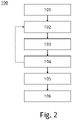
- Figure 2 shows a method 100 for designing and manufacturing a component. The method comprises the following steps:
- Figure 3 shows a method 200 to design and manufacture a component.
- the method 200 starts at step 201 (component design).
- a component is designed by providing, designing or otherwise creating a model of the component.
- the model may comprise a set of definitions that characterize the physical properties, in particular the geometry of the component to be manufactured.
- the model is provided to a finite elements modal analysis performed at step 202 (FE modal analysis to determine mode shapes and natural frequencies).
- FE modal analysis to determine mode shapes and natural frequencies.
- the modal analysis may determine mode shapes and natural frequencies of a component having the design of the model. This may be performed by a computer.
- a harmonic response is determined, e.g., by a harmonic response analysis.
- maximum stress profiles may be determined and/or provided, e.g. a maximum stress profile of the component to be manufactured.
- a speed envelope e.g., of a gas turbine for which the component is to be manufactured for (and during a flight)
- dimensional tolerances dimensional tolerances of the component to be manufactured and/or of adjacent components in the engine are determined and/or provided.
- a mode shape may be determined to be critical when it creates or potentially leads to a critical resonance, e.g. having a destructive effect on the component or adjacent components in the engine (or, in general, machine).
- Further input to the critical mode shapes identification at step 204 may be provided as test results from tests in steps 211 (engine subsystem test), 212 (engine test) and/or 213 (flight test, in particular for a retrofit).
- Steps 202 and 203 computer simulations may be applied. For example, a design failure mode and effects analysis, DFMEA, and/or a finite element analysis, FEA. Steps 211 to 213 may provide hardware-based tests that are performed based on a given component design, represented by the model provided in step 201 (or step 101 in Figure 1 ).
- critical mode shapes are identified.
- the mode shape(s) on which to variate the geometry of the component may be identified upon conjoint consideration of an operational speed range and the identification of critical mode shapes that require to be eliminated, or reduced to a maximum extent.
- the mode shape chosen for altering the geometry may be a non-critical one, out of range and able to mismatching the geometrical periodicities expected to excite resonances during operation.
- the mode shape for the stiffness paths may be chosen in order to optimize the disruption of other critical mode shapes at other frequencies.
- step 208 identification of the mode shape for modal stiffening
- a mode shape to be used for a mode-shape specific component stiffening is identified.
- the results or a subset of the results of the performance of step 202 may be provided to be used at step 208.
- the identified mode shape (e.g., as shown in the first row, third column of Figure 1 ), is then provided to a mode-shaped design application at step 209.
- the component design i.e., the model of the component
- the component design is redesigned (modified) so as to at least partially follow the form of the mode shape.
- An excitation of the mode shape (e.g., a maximum deflection) may be translated to or "frozen" in the redesigned model of the component.
- the redesigned model and the outcome of step 204 are provided and analyzed at step 210 (vibration reduced to target evaluation).
- the redesigned model is provided (indicated as 214), for manufacturing the component in accordance with the redesigned model at step 215 (manufacturing).
- the method may return to step 209 (and from there either to step 201 or to step 210) or to step 201.
- Figures 4A to 4C show geometries of two versions of a component 50, in the present example a ring gear front diaphragm, having a disc portion 51 and a cylindrical portion 52.
- Figure 4A shows the component 50 in accordance with a model M.
- the model M is provided at step 101 or 201 of the method 100; 200 of Figure 2 or 3 .
- the method 100 of Figure 2 or the method 200 of Figure 3 is then performed, wherein a redesigned model M' is created.
- the component 50 is manufactured in accordance with the redesigned model M'.
- Figure 4C shows an optional way of stiffening portions in accordance with a mode shape by adding one or more reinforcements 53 in a pattern that corresponds to the mode shape (indicated by dashed lines).
- the reinforcements 53 may be formed as stiffening ribs and/or local thickness variations.
- Another option is to arrange a composite material (or portions thereof) along the mode shape.
- FIGS 5A and 5B show two versions of another component 60.
- This component 60 is a ring gear mount for mounting a ring gear 38 of a gearbox of a gas turbine engine to a stationary structure of the gas turbine engine by means of a flange 61.
- the gas turbine engine, gearbox and ring gear 38 will be described in greater detail below with reference to Figures 6 to 8 .
- Figure 5A shows the component 60 designed in accordance with a model M that has not yet been tuned on a mode shape, and excited in an operating range of frequencies and intensities. Local deformations are very pronounced and lead to stresses on the component 60 which may reduce its lifetime.
- the mode shape is a critical 8-diameter mode shape.
- Figure 5B shows a version of the component 60 manufactured in accordance with the method 100; 200 of Figure 2 or 3 (in accordance with a redesigned model M') at the excitation as shown in Figure 5A .
- Stresses are more smoothly distributed over the component 60, so that it can withstand the stresses more stably.
- the lifetime of the component 60 according to the redesigned model M' may be increased.
- the weight of the component 60 may be reduced.
- vibrations of the component can be optimized.
- Manufacturing a component 50; 60 in accordance with the method 100; 200 allows to reproduce a non-critical mode shape stiffness distribution.
- the whole distribution of stiffness of a non-critical mode shape can be used in order to alter the component stiffness and geometry so that the vibration due other, critical mode shapes cannot take place any longer, even if the natural frequency remains within the operational range.
- FIG. 6 illustrates a gas turbine engine 10 for an aircraft.
- the gas turbine engine 10 has a principal rotational axis 9.
- the engine 10 comprises an air intake 12 and a propulsive fan 23 that generates two airflows: a core airflow A and a bypass airflow B.
- the gas turbine engine 10 comprises a core 11 that receives the core airflow A.
- the engine core 11 comprises, in axial flow series, a low pressure compressor 14, a high-pressure compressor 15, combustion equipment 16, a high-pressure turbine 17, a low pressure turbine 19 and a core exhaust nozzle 20.
- a nacelle 21 surrounds the gas turbine engine 10 and defines a bypass duct 22 and a bypass exhaust nozzle 18.
- the bypass airflow B flows through the bypass duct 22.
- the fan 23 is attached to and driven by the low pressure turbine 19 via a shaft 26 (low-pressure shaft) and an epicyclic gearbox.
- the core airflow A is accelerated and compressed by the low pressure compressor 14 and directed into the high pressure compressor 15 where further compression takes place.
- the compressed air exhausted from the high pressure compressor 15 is directed into the combustion equipment 16 where it is mixed with fuel and the mixture is combusted.
- the resultant hot combustion products then expand through, and thereby drive, the high pressure and low pressure turbines 17, 19 before being exhausted through the nozzle 20 to provide some propulsive thrust.
- the high pressure turbine 17 drives the high pressure compressor 15 by a suitable interconnecting shaft 27 (high-pressure shaft).
- the fan 23 generally provides the majority of the propulsive thrust.
- the epicyclic gearbox 30 is a reduction gearbox.
- the gas turbine engine 10 comprises one or more components designed in accordance with the method 100; 200 of Figure 2 and/or 3, e.g. a ring gear mount of the gearbox 30.
- FIG. 7 An exemplary arrangement for a geared fan gas turbine engine 10 is shown in Figure 7 .
- the low pressure turbine 19 (see Figure 6 ) drives the shaft 26, which is coupled to a sun wheel, or sun gear, 28 of the epicyclic gear arrangement 30.
- a sun wheel, or sun gear, 28 of the epicyclic gear arrangement 30 Radially outwardly of the sun gear 28 and intermeshing therewith is a plurality of planet gears 32 that are coupled together by a planet carrier 34.
- the planet carrier 34 constrains the planet gears 32 to precess around the sun gear 28 in synchronicity whilst enabling each planet gear 32 to rotate about its own axis.
- the planet carrier 34 is coupled via linkages 36 to the fan 23 in order to drive its rotation about the engine axis 9.
- an annulus or ring gear 38 Radially outwardly of the planet gears 32 and intermeshing therewith is an annulus or ring gear 38 that is coupled, via the ring gear mount 60 and linkages 40, to a stationary supporting structure 24
- low pressure turbine and “low pressure compressor” as used herein may be taken to mean the lowest pressure turbine stages and lowest pressure compressor stages (i.e. not including the fan 23) respectively and/or the turbine and compressor stages that are connected together by the interconnecting shaft 26 with the lowest rotational speed in the engine (i.e. not including the gearbox output shaft that drives the fan 23).
- the "low pressure turbine” and “low pressure compressor” referred to herein may alternatively be known as the "intermediate pressure turbine” and “intermediate pressure compressor”. Where such alternative nomenclature is used, the fan 23 may be referred to as a first, or lowest pressure, compression stage.
- the epicyclic gearbox 30 is shown by way of example in greater detail in Figure 8 .
- Each of the sun gear 28, planet gears 32 and ring gear 38 comprise teeth about their periphery to intermesh with the other gears. However, for clarity only exemplary portions of the teeth are illustrated in Figure 8 .
- Practical applications of a planetary epicyclic gearbox 30 generally comprise at least three planet gears 32.
- the epicyclic gearbox 30 illustrated by way of example in Figures 7 and 8 is of the planetary type, in that the planet carrier 34 is coupled to an output shaft via linkages 36, with the ring gear 38 fixed.
- the epicyclic gearbox 30 may be a star arrangement, in which the planet carrier 34 is held fixed, with the ring (or annulus) gear 38 allowed to rotate. In such an arrangement the fan 23 is driven by the ring gear 38.
- the gearbox 30 may be a differential gearbox in which the ring gear 38 and the planet carrier 34 are both allowed to rotate.
- any suitable arrangement may be used for locating the gearbox 30 in the engine 10 and/or for connecting the gearbox 30 to the engine 10.
- the connections (such as the linkages 36, 40 in the Figure 7 example) between the gearbox 30 and other parts of the engine 10 (such as the input shaft 26, the output shaft and the fixed structure 24) may have any desired degree of stiffness or flexibility.
- any suitable arrangement of the bearings between rotating and stationary parts of the engine may be used, and the disclosure is not limited to the exemplary arrangement of Figure 7 .
- the gearbox 30 has a star arrangement (described above)
- the skilled person would readily understand that the arrangement of output and support linkages and bearing locations would typically be different to that shown by way of example in Figure 7 .
- the present disclosure extends to a gas turbine engine having any arrangement of gearbox styles (for example star or planetary), support structures, input and output shaft arrangement, and bearing locations.
- gearbox styles for example star or planetary
- support structures for example star or planetary
- input and output shaft arrangement for example star or planetary
- bearing locations for example star or planetary
- the gearbox may drive additional and/or alternative components (e.g. the intermediate pressure compressor and/or a booster compressor).
- additional and/or alternative components e.g. the intermediate pressure compressor and/or a booster compressor.
- gas turbine engines to which the present disclosure may be applied may have alternative configurations.
- such engines may have an alternative number of compressors and/or turbines and/or an alternative number of interconnecting shafts.
- the gas turbine engine shown in Figure 6 has a split flow nozzle 20, 22 meaning that the flow through the bypass duct 22 has its own nozzle that is separate to and radially outside the core engine nozzle 20.
- this is not limiting, and any aspect of the present disclosure may also apply to engines in which the flow through the bypass duct 22 and the flow through the core 11 are mixed, or combined, before (or upstream of) a single nozzle, which may be referred to as a mixed flow nozzle.
- One or both nozzles may have a fixed or variable area.
- the described example relates to a turbofan engine, the disclosure may apply, for example, to any type of gas turbine engine, such as an open rotor (in which the fan stage is not surrounded by a nacelle) or turboprop engine, for example.
- the gas turbine engine 10 may not comprise a gearbox 30.
- the geometry of the gas turbine engine 10, and components thereof, is defined by a conventional axis system, comprising an axial direction (which is aligned with the rotational axis 9), a radial direction (in the bottom-to-top direction in Figure 6 ), and a circumferential direction (perpendicular to the page in the Figure 6 view).
- the axial, radial and circumferential directions are mutually perpendicular.
- FIG 9 shows an aircraft 8 in the form of a passenger aircraft.
- Aircraft 8 comprises several (i.e., two) gas turbine engines 10 in accordance with Figures 6 to 8 .
- the identification of the out-of-range mode shape(s) may target the stiffness and mass distributions may result in an effective reduction of the vibration throughout wide gas turbine engine 10 speed ranges where vibrations are deemed to be critical for the engine operation.
- the invention may be applied particularly to components of gas turbines, such as gas turbine engines, and power plants, rigs , engine mounts, large frames, buildings, civil structures, as well as in turbines, pumps, bearings, accessory and power gearboxes and others, but it can also be applied to components of other machines, in particular any type of engine. It is also worth noting that the methods described herein can optionally be used to redesign a component for retrofitting a part, e.g., when it has been found that the part vibrates critically in use.
- components particularly suitable for being redesigned as described herein are housings, static structures, struts, vanes and blades.
- the modification of geometry upon mode-shape patterns may further be combined with the use of composite materials or single crystals (e.g. for blades).
Landscapes
- Engineering & Computer Science (AREA)
- Physics & Mathematics (AREA)
- Theoretical Computer Science (AREA)
- Geometry (AREA)
- General Engineering & Computer Science (AREA)
- General Physics & Mathematics (AREA)
- Computer Hardware Design (AREA)
- Evolutionary Computation (AREA)
- Mathematical Optimization (AREA)
- Computational Mathematics (AREA)
- Mathematical Analysis (AREA)
- Pure & Applied Mathematics (AREA)
- Mechanical Engineering (AREA)
- Aviation & Aerospace Engineering (AREA)
- Automation & Control Theory (AREA)
- Chemical & Material Sciences (AREA)
- Combustion & Propulsion (AREA)
- Turbine Rotor Nozzle Sealing (AREA)
- Structures Of Non-Positive Displacement Pumps (AREA)
Claims (13)
- Procédé (100 ; 200) de fabrication d'un composant (50 ; 60), comprenant :- la conception ou la réception (101 ; 201) d'un modèle (M) du composant (50 ; 60) ;- la détermination (102 ; 202) d'au moins une forme de mode d'au moins une partie du modèle (M) ;- la reconception (103 ; 209) du modèle (M) sur la base de l'au moins une forme de mode déterminée pour obtenir un modèle reconçu (M') du composant (50 ; 60),le modèle (M) étant reconçu conformément à un modèle de déformation de l'au moins une forme de mode de sorte qu'une rigidité et/ou une distribution de masse suit le modèle de déformation ; etla fabrication (106) du composant (50 ; 60) conformément au modèle reconçu (M').
- Procédé (100 ; 200) selon la revendication 1, l'au moins une forme de mode étant non critique.
- Procédé (100 ; 200) selon la revendication 1 ou 2, la détermination (102 ; 202) d'une ou plusieurs formes de mode du composant (50 ; 60) étant réalisée en dehors d'une plage de fonctionnement normal par rapport à une condition de fonctionnement du composant.
- Procédé (100 ; 200) selon la revendication 3, la reconception (103 ; 209) du modèle (M) étant réalisée de manière à ajuster la rigidité du composant conformément à l'au moins une forme de mode hors de la plage de fonctionnement.
- Procédé (100 ; 200) selon l'une quelconque des revendications précédentes, la reconception (103 ; 209) du modèle comprenant la modification d'une géométrie et/ou d'une distribution de masse.
- Procédé (100 ; 200) selon l'une quelconque des revendications précédentes, la reconception (103 ; 209) du modèle comprenant la modification d'une rigidité.
- Procédé (100 ; 200) selon la revendication 6, la rigidité étant modifiée par l'ajout ou la suppression d'un renfort (53).
- Procédé (100 ; 200) selon l'une quelconque des revendications précédentes, comprenant en outre la vérification (104) qu'une réponse vibratoire du composant (50 ; 60) dans une plage de fonctionnement est réduite après la reconception du modèle (M).
- Procédé (100 ; 200) selon l'une quelconque des revendications précédentes, comprenant en outre la réalisation itérative des étapes de détermination (102), de reconception (103) et/ou de vérification (104) plusieurs fois.
- Procédé (100 ; 200) selon l'une quelconque des revendications précédentes, avant que le modèle (M) ne soit reconçu, le composant (50 ; 60) étant sélectionné parmi une pluralité de composants en déterminant un composant d'une turbine à gaz (10), qui produit des harmoniques de vibration et/ou des harmoniques critiques, par une analyse des modes de défaillance et des effets de la conception, DFMEA, et/ou une analyse par éléments finis, FEA.
- Composant (50 ; 60) fabriqué selon l'une quelconque des revendications précédentes.
- Composant (60) selon la revendication 11, le composant (60) étant un composant d'une boîte d'engrenages de puissance (30) de moteur à turbine à gaz (10).
- Turbine à gaz (10) comprenant un ou plusieurs composants (60) de la revendication 11 ou 12.
Priority Applications (3)
| Application Number | Priority Date | Filing Date | Title |
|---|---|---|---|
| EP19175620.4A EP3741981B1 (fr) | 2019-05-21 | 2019-05-21 | Composants à forme de mode |
| US16/868,723 US11645436B2 (en) | 2019-05-21 | 2020-05-07 | Mode-shaped components |
| CN202010435312.0A CN111985046A (zh) | 2019-05-21 | 2020-05-21 | 模态成形的部件 |
Applications Claiming Priority (1)
| Application Number | Priority Date | Filing Date | Title |
|---|---|---|---|
| EP19175620.4A EP3741981B1 (fr) | 2019-05-21 | 2019-05-21 | Composants à forme de mode |
Publications (2)
| Publication Number | Publication Date |
|---|---|
| EP3741981A1 EP3741981A1 (fr) | 2020-11-25 |
| EP3741981B1 true EP3741981B1 (fr) | 2023-03-15 |
Family
ID=66676190
Family Applications (1)
| Application Number | Title | Priority Date | Filing Date |
|---|---|---|---|
| EP19175620.4A Active EP3741981B1 (fr) | 2019-05-21 | 2019-05-21 | Composants à forme de mode |
Country Status (3)
| Country | Link |
|---|---|
| US (1) | US11645436B2 (fr) |
| EP (1) | EP3741981B1 (fr) |
| CN (1) | CN111985046A (fr) |
Families Citing this family (1)
| Publication number | Priority date | Publication date | Assignee | Title |
|---|---|---|---|---|
| CN114091330B (zh) * | 2021-11-16 | 2024-05-14 | 韩建国 | 一种大功率风电磁齿轮箱的中高速级磁齿轮优化设计方法 |
Family Cites Families (14)
| Publication number | Priority date | Publication date | Assignee | Title |
|---|---|---|---|---|
| AU5006900A (en) * | 1999-05-13 | 2000-12-05 | Rolls-Royce Corporation | Method for designing a cyclic symmetric structure |
| GB0019434D0 (en) * | 2000-08-09 | 2000-09-27 | Rolls Royce Plc | A device and method for fatigue testing of materials |
| GB0325215D0 (en) * | 2003-10-29 | 2003-12-03 | Rolls Royce Plc | Design of vanes for exposure to vibratory loading |
| US7280950B2 (en) * | 2004-01-22 | 2007-10-09 | Electro-Motive Diesel, Inc. | Locomotive diesel engine turbocharger and turbine stage constructed with turbine blade vibration suppression methodology |
| US8209839B1 (en) * | 2006-11-28 | 2012-07-03 | Florida Turbine Technologies, Inc. | Process for re-designing a distressed component used under thermal and structural loading |
| ATE525505T1 (de) * | 2007-11-09 | 2011-10-15 | Vestas Wind Sys As | Verfahren zur herstellung eines windturbinenblatts und verwendung einer lasttragenden matte zur armierung einer windturbinenblattkonstruktion |
| JP2011042138A (ja) * | 2009-08-24 | 2011-03-03 | Canon Inc | 光学素子の製造方法及び画像形成装置 |
| GB2490127A (en) * | 2011-04-19 | 2012-10-24 | Rolls Royce Plc | Aerofoil assembly |
| US8713511B1 (en) * | 2011-09-16 | 2014-04-29 | Suvolta, Inc. | Tools and methods for yield-aware semiconductor manufacturing process target generation |
| US10423730B2 (en) * | 2014-10-02 | 2019-09-24 | Siemens Industry Software Nv | Contact modeling between objects |
| US10641281B2 (en) * | 2016-08-08 | 2020-05-05 | United Technologies Corporation | Mistuned laminate airfoil |
| US20180314767A1 (en) * | 2017-04-28 | 2018-11-01 | General Electric Company | Systems and methods for improved characteristic accountability & verification (ecav) system |
| US11280751B2 (en) * | 2018-12-04 | 2022-03-22 | General Electric Company | System and method for optimizing a manufacturing process based on an inspection of a component |
| US11797728B2 (en) * | 2020-04-30 | 2023-10-24 | Ansys, Inc. | Automating extraction of material model coefficients for simulations |
-
2019
- 2019-05-21 EP EP19175620.4A patent/EP3741981B1/fr active Active
-
2020
- 2020-05-07 US US16/868,723 patent/US11645436B2/en active Active
- 2020-05-21 CN CN202010435312.0A patent/CN111985046A/zh active Pending
Also Published As
| Publication number | Publication date |
|---|---|
| EP3741981A1 (fr) | 2020-11-25 |
| CN111985046A (zh) | 2020-11-24 |
| US20200372192A1 (en) | 2020-11-26 |
| US11645436B2 (en) | 2023-05-09 |
Similar Documents
| Publication | Publication Date | Title |
|---|---|---|
| EP3854997A1 (fr) | Positionnement de turbine amélioré dans un moteur à turbine à gaz | |
| EP3839232A1 (fr) | Moteur à turbine à gaz comportant un arbre à trois paliers | |
| US11645436B2 (en) | Mode-shaped components | |
| US10822965B2 (en) | Active airfoil vibration control | |
| US20120288373A1 (en) | Rotor with asymmetric blade spacing | |
| US11898498B2 (en) | Method and system for reducing cross-shaft vibrations | |
| EP3825579B1 (fr) | Procédé et système de réduction des vibrations dans des machines tournantes | |
| EP3839231A1 (fr) | Moteur à turbine à gaz à vibrations réduites | |
| US8375698B2 (en) | Method for reducing the vibration levels of a propfan of contrarotating bladed disks of a turbine engine | |
| EP3839230A1 (fr) | Roulements d'arbre à rigidité améliorée | |
| US10781827B1 (en) | Gas turbine engine airfoil frequency design | |
| EP3734109B1 (fr) | Procédé et système de réduction de vibrations d'arbre transversal | |
| US10677266B1 (en) | Gas turbine engine airfoil frequency design | |
| US10788049B1 (en) | Gas turbine engine airfoil frequency design | |
| Ivanov et al. | Nonlinear reduced dynamic model of turbofan engine for investigation of engine structural frame vibrations after fan blade out event | |
| US10711623B1 (en) | Gas turbine engine airfoil frequency design | |
| US10669856B1 (en) | Gas turbine engine airfoil frequency design | |
| US10844727B1 (en) | Gas turbine engine airfoil frequency design | |
| US10683761B1 (en) | Gas turbine engine airfoil frequency design | |
| US10801364B1 (en) | Gas turbine engine airfoil frequency design | |
| US10815785B1 (en) | Gas turbine engine airfoil frequency design | |
| US10865809B1 (en) | Gas turbine engine airfoil frequency design | |
| US10760592B1 (en) | Gas turbine engine airfoil frequency design | |
| US10774651B1 (en) | Gas turbine engine airfoil frequency design | |
| US10808544B1 (en) | Gas turbine engine airfoil frequency design |
Legal Events
| Date | Code | Title | Description |
|---|---|---|---|
| PUAI | Public reference made under article 153(3) epc to a published international application that has entered the european phase |
Free format text: ORIGINAL CODE: 0009012 |
|
| STAA | Information on the status of an ep patent application or granted ep patent |
Free format text: STATUS: THE APPLICATION HAS BEEN PUBLISHED |
|
| AK | Designated contracting states |
Kind code of ref document: A1 Designated state(s): AL AT BE BG CH CY CZ DE DK EE ES FI FR GB GR HR HU IE IS IT LI LT LU LV MC MK MT NL NO PL PT RO RS SE SI SK SM TR |
|
| AX | Request for extension of the european patent |
Extension state: BA ME |
|
| STAA | Information on the status of an ep patent application or granted ep patent |
Free format text: STATUS: REQUEST FOR EXAMINATION WAS MADE |
|
| 17P | Request for examination filed |
Effective date: 20210517 |
|
| RBV | Designated contracting states (corrected) |
Designated state(s): AL AT BE BG CH CY CZ DE DK EE ES FI FR GB GR HR HU IE IS IT LI LT LU LV MC MK MT NL NO PL PT RO RS SE SI SK SM TR |
|
| GRAP | Despatch of communication of intention to grant a patent |
Free format text: ORIGINAL CODE: EPIDOSNIGR1 |
|
| STAA | Information on the status of an ep patent application or granted ep patent |
Free format text: STATUS: GRANT OF PATENT IS INTENDED |
|
| INTG | Intention to grant announced |
Effective date: 20221004 |
|
| GRAS | Grant fee paid |
Free format text: ORIGINAL CODE: EPIDOSNIGR3 |
|
| GRAA | (expected) grant |
Free format text: ORIGINAL CODE: 0009210 |
|
| STAA | Information on the status of an ep patent application or granted ep patent |
Free format text: STATUS: THE PATENT HAS BEEN GRANTED |
|
| AK | Designated contracting states |
Kind code of ref document: B1 Designated state(s): AL AT BE BG CH CY CZ DE DK EE ES FI FR GB GR HR HU IE IS IT LI LT LU LV MC MK MT NL NO PL PT RO RS SE SI SK SM TR |
|
| REG | Reference to a national code |
Ref country code: CH Ref legal event code: EP Ref country code: GB Ref legal event code: FG4D |
|
| REG | Reference to a national code |
Ref country code: DE Ref legal event code: R096 Ref document number: 602019026330 Country of ref document: DE |
|
| REG | Reference to a national code |
Ref country code: IE Ref legal event code: FG4D |
|
| REG | Reference to a national code |
Ref country code: AT Ref legal event code: REF Ref document number: 1554130 Country of ref document: AT Kind code of ref document: T Effective date: 20230415 |
|
| REG | Reference to a national code |
Ref country code: LT Ref legal event code: MG9D |
|
| P01 | Opt-out of the competence of the unified patent court (upc) registered |
Effective date: 20230528 |
|
| REG | Reference to a national code |
Ref country code: NL Ref legal event code: MP Effective date: 20230315 |
|
| PG25 | Lapsed in a contracting state [announced via postgrant information from national office to epo] |
Ref country code: RS Free format text: LAPSE BECAUSE OF FAILURE TO SUBMIT A TRANSLATION OF THE DESCRIPTION OR TO PAY THE FEE WITHIN THE PRESCRIBED TIME-LIMIT Effective date: 20230315 Ref country code: NO Free format text: LAPSE BECAUSE OF FAILURE TO SUBMIT A TRANSLATION OF THE DESCRIPTION OR TO PAY THE FEE WITHIN THE PRESCRIBED TIME-LIMIT Effective date: 20230615 Ref country code: LV Free format text: LAPSE BECAUSE OF FAILURE TO SUBMIT A TRANSLATION OF THE DESCRIPTION OR TO PAY THE FEE WITHIN THE PRESCRIBED TIME-LIMIT Effective date: 20230315 Ref country code: LT Free format text: LAPSE BECAUSE OF FAILURE TO SUBMIT A TRANSLATION OF THE DESCRIPTION OR TO PAY THE FEE WITHIN THE PRESCRIBED TIME-LIMIT Effective date: 20230315 Ref country code: HR Free format text: LAPSE BECAUSE OF FAILURE TO SUBMIT A TRANSLATION OF THE DESCRIPTION OR TO PAY THE FEE WITHIN THE PRESCRIBED TIME-LIMIT Effective date: 20230315 |
|
| PGFP | Annual fee paid to national office [announced via postgrant information from national office to epo] |
Ref country code: FR Payment date: 20230523 Year of fee payment: 5 Ref country code: DE Payment date: 20230530 Year of fee payment: 5 |
|
| REG | Reference to a national code |
Ref country code: AT Ref legal event code: MK05 Ref document number: 1554130 Country of ref document: AT Kind code of ref document: T Effective date: 20230315 |
|
| PG25 | Lapsed in a contracting state [announced via postgrant information from national office to epo] |
Ref country code: SE Free format text: LAPSE BECAUSE OF FAILURE TO SUBMIT A TRANSLATION OF THE DESCRIPTION OR TO PAY THE FEE WITHIN THE PRESCRIBED TIME-LIMIT Effective date: 20230315 Ref country code: NL Free format text: LAPSE BECAUSE OF FAILURE TO SUBMIT A TRANSLATION OF THE DESCRIPTION OR TO PAY THE FEE WITHIN THE PRESCRIBED TIME-LIMIT Effective date: 20230315 Ref country code: GR Free format text: LAPSE BECAUSE OF FAILURE TO SUBMIT A TRANSLATION OF THE DESCRIPTION OR TO PAY THE FEE WITHIN THE PRESCRIBED TIME-LIMIT Effective date: 20230616 Ref country code: FI Free format text: LAPSE BECAUSE OF FAILURE TO SUBMIT A TRANSLATION OF THE DESCRIPTION OR TO PAY THE FEE WITHIN THE PRESCRIBED TIME-LIMIT Effective date: 20230315 |
|
| PG25 | Lapsed in a contracting state [announced via postgrant information from national office to epo] |
Ref country code: SM Free format text: LAPSE BECAUSE OF FAILURE TO SUBMIT A TRANSLATION OF THE DESCRIPTION OR TO PAY THE FEE WITHIN THE PRESCRIBED TIME-LIMIT Effective date: 20230315 Ref country code: RO Free format text: LAPSE BECAUSE OF FAILURE TO SUBMIT A TRANSLATION OF THE DESCRIPTION OR TO PAY THE FEE WITHIN THE PRESCRIBED TIME-LIMIT Effective date: 20230315 Ref country code: PT Free format text: LAPSE BECAUSE OF FAILURE TO SUBMIT A TRANSLATION OF THE DESCRIPTION OR TO PAY THE FEE WITHIN THE PRESCRIBED TIME-LIMIT Effective date: 20230717 Ref country code: ES Free format text: LAPSE BECAUSE OF FAILURE TO SUBMIT A TRANSLATION OF THE DESCRIPTION OR TO PAY THE FEE WITHIN THE PRESCRIBED TIME-LIMIT Effective date: 20230315 Ref country code: EE Free format text: LAPSE BECAUSE OF FAILURE TO SUBMIT A TRANSLATION OF THE DESCRIPTION OR TO PAY THE FEE WITHIN THE PRESCRIBED TIME-LIMIT Effective date: 20230315 Ref country code: CZ Free format text: LAPSE BECAUSE OF FAILURE TO SUBMIT A TRANSLATION OF THE DESCRIPTION OR TO PAY THE FEE WITHIN THE PRESCRIBED TIME-LIMIT Effective date: 20230315 Ref country code: AT Free format text: LAPSE BECAUSE OF FAILURE TO SUBMIT A TRANSLATION OF THE DESCRIPTION OR TO PAY THE FEE WITHIN THE PRESCRIBED TIME-LIMIT Effective date: 20230315 |
|
| PGFP | Annual fee paid to national office [announced via postgrant information from national office to epo] |
Ref country code: GB Payment date: 20230523 Year of fee payment: 5 |
|
| PG25 | Lapsed in a contracting state [announced via postgrant information from national office to epo] |
Ref country code: SK Free format text: LAPSE BECAUSE OF FAILURE TO SUBMIT A TRANSLATION OF THE DESCRIPTION OR TO PAY THE FEE WITHIN THE PRESCRIBED TIME-LIMIT Effective date: 20230315 Ref country code: PL Free format text: LAPSE BECAUSE OF FAILURE TO SUBMIT A TRANSLATION OF THE DESCRIPTION OR TO PAY THE FEE WITHIN THE PRESCRIBED TIME-LIMIT Effective date: 20230315 Ref country code: IS Free format text: LAPSE BECAUSE OF FAILURE TO SUBMIT A TRANSLATION OF THE DESCRIPTION OR TO PAY THE FEE WITHIN THE PRESCRIBED TIME-LIMIT Effective date: 20230715 |
|
| REG | Reference to a national code |
Ref country code: DE Ref legal event code: R097 Ref document number: 602019026330 Country of ref document: DE |
|
| REG | Reference to a national code |
Ref country code: CH Ref legal event code: PL |
|
| PG25 | Lapsed in a contracting state [announced via postgrant information from national office to epo] |
Ref country code: MC Free format text: LAPSE BECAUSE OF FAILURE TO SUBMIT A TRANSLATION OF THE DESCRIPTION OR TO PAY THE FEE WITHIN THE PRESCRIBED TIME-LIMIT Effective date: 20230315 |
|
| PLBE | No opposition filed within time limit |
Free format text: ORIGINAL CODE: 0009261 |
|
| STAA | Information on the status of an ep patent application or granted ep patent |
Free format text: STATUS: NO OPPOSITION FILED WITHIN TIME LIMIT |
|
| REG | Reference to a national code |
Ref country code: BE Ref legal event code: MM Effective date: 20230531 |
|
| PG25 | Lapsed in a contracting state [announced via postgrant information from national office to epo] |
Ref country code: SI Free format text: LAPSE BECAUSE OF FAILURE TO SUBMIT A TRANSLATION OF THE DESCRIPTION OR TO PAY THE FEE WITHIN THE PRESCRIBED TIME-LIMIT Effective date: 20230315 Ref country code: MC Free format text: LAPSE BECAUSE OF FAILURE TO SUBMIT A TRANSLATION OF THE DESCRIPTION OR TO PAY THE FEE WITHIN THE PRESCRIBED TIME-LIMIT Effective date: 20230315 Ref country code: LU Free format text: LAPSE BECAUSE OF NON-PAYMENT OF DUE FEES Effective date: 20230521 Ref country code: LI Free format text: LAPSE BECAUSE OF NON-PAYMENT OF DUE FEES Effective date: 20230531 Ref country code: DK Free format text: LAPSE BECAUSE OF FAILURE TO SUBMIT A TRANSLATION OF THE DESCRIPTION OR TO PAY THE FEE WITHIN THE PRESCRIBED TIME-LIMIT Effective date: 20230315 Ref country code: CH Free format text: LAPSE BECAUSE OF NON-PAYMENT OF DUE FEES Effective date: 20230531 |
|
| 26N | No opposition filed |
Effective date: 20231218 |
|
| REG | Reference to a national code |
Ref country code: IE Ref legal event code: MM4A |
|
| PG25 | Lapsed in a contracting state [announced via postgrant information from national office to epo] |
Ref country code: IE Free format text: LAPSE BECAUSE OF NON-PAYMENT OF DUE FEES Effective date: 20230521 |
|
| PG25 | Lapsed in a contracting state [announced via postgrant information from national office to epo] |
Ref country code: IE Free format text: LAPSE BECAUSE OF NON-PAYMENT OF DUE FEES Effective date: 20230521 |